Lexicon MPX 500 Service Manual
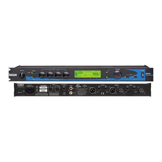
24-bit dual channel processor
Hide thumbs
Also See for MPX 500:
- User manual (58 pages) ,
- Release note (2 pages) ,
- Midi implementation manual (58 pages)
Table of Contents
Advertisement
Quick Links
Advertisement
Table of Contents
Troubleshooting

Subscribe to Our Youtube Channel
Related Manuals for Lexicon MPX 500


Summary of Contents for Lexicon MPX 500
- Page 1 MPX 500 24-Bit Dual Channel Processor Service Manual...
- Page 2 Copyright © 1999 Lexicon, Inc. All Rights Reserved Lexicon Inc. ● 3 Oak Park ● Bedford, MA 01730-1441 ● Tel (781) 280-0300 ● Customer Service Fax (781) 280-0499 Lexicon Part # 070-14399 Rev 0 Printed in the United States of America...
- Page 3 MPX 500 Service Manual...
- Page 4 MPX 500 Service Manual...
-
Page 5: Table Of Contents
Verify Clean Audio ..........................4-4 Shock Test ............................4-4 Lexicon Audio Precision ATE Summary ....................4-5 Chapter 5 Troubleshooting ................. 5-1 Check the Lexicon web site for the latest software and information:..........5-1 Diagnostics .............................. 5-1 Power Up Diagnostics.......................... 5-1 Error Indication............................. 5-1 Test Descriptions .......................... - Page 6 MPX 500 Service Manual Footswitches: ............................5-5 Front Panel Switches: ........................5-6 #9 Encoder Test:..........................5-6 #10 MIDI Test:...........................5-7 #11 LCD Test: ...........................5-7 #12 Exit Test: ............................5-7 #13 Initialize Test: ..........................5-7 #14 Unused:............................5-7 #15 Unused:............................5-7 #16 Burn In Test:..........................5-7 General Troubleshooting and Service Notes....................5-8 Power Supply............................5-8...
-
Page 7: Chapter 1 Reference Documents, Required Equipment
Lexicon Chapter 1 Refe r ence Documents, Required Equipment Reference Documents MPX 500 User Guide - Lexicon P/N 070-14116 or latest revision Required Equipment Tools The following is a minimum suggested technician's tool kit required for performing disassembly, assembly and repairs: •... -
Page 9: Chapter 2 General Information
Return Authorization from Lexicon. If Lexicon recommends that a MPX 500 be returned for repair and you choose to return the unit to Lexicon for service, Lexicon assumes no responsibility for the unit in shipment from the customer to the factory, whether the unit is in or out of warranty. -
Page 11: Chapter 3 Specifications
Lexicon Chapter 3 Spec i fications Analog Inputs Connectors: XLR/TRS balanced Impedance: 50k balanced; 25kΩ unbalanced A/D Dynamic Range: 1058dB, typical Levels: +20 to +8dBu full scale Resolution: 24-Bit Sigma-Delta Conversion Analog Outputs Connectors: XLR/TRS balanced Impedance: <600Ω D/A Dynamic Range: 101dB, typical Levels: +26dBu balanced;... -
Page 13: Chapter 4 Performance Verification
Lexicon Chapter 4 Perfo r mance Verification This section describes a quick verification of the operation of the MPX 500 and the integrity of its analog and digital audio signal paths. Diagnostics: The MXP 500 contains two types of Diagnostics: Power Up Diagnostics, and Extended Diagnostics. Each of these will be described fully in Chapter 5: Troubleshooting. -
Page 14: Thd+N Test
Select Internal 48k Clock Source from System mode and repeat all of the above tests. Digital I/O Functionality This test will verify that the MPX 500 will pass a valid S/PDIF digital audio signal through its digital input and output circuitry. -
Page 15: Midi Functionality
To enter the Extended Diagnostics, power on the unit while pressing down & holding the BYPASS button on the front panel of the MPX 500. When the EDIT LED is lit the BYPASS button can be released. After it is released, the EDIT LED will go out and the LCD Display will indicate the first test, # 1 ROM. -
Page 16: Listening Test
Listening Test: Setup 1. Connect an audio cable between the output of the Low Distortion Amplifier and the MPX 500 Left and Right Inputs. 2. Connect two audio cables between the headphone amplifier inputs and the MPX 500 Left and Right outputs. -
Page 17: Lexicon Audio Precision Ate Summary
Lexicon Lexicon Audio Precision ATE Summary... -
Page 19: Chapter 5 Troubleshooting
On Normal power up, the MXP 500 will automatically execute a set of tests that comprise the Power Up Diagnostics. All front panel LEDs will be turned on for approximately 200ms, and then the MPX 500 will attempt to run the following sequence of tests. The tests have been designed to take less than 10 seconds. -
Page 20: Test Descriptions
ARU Registers and as scratchpad memory. #6 EEPROM Test: This test will verify the functions of the EEPROM on the MPX 500. First the test will verify that the EEPROM has been initialized properly. This is done by storing the software... -
Page 21: Extended Diagnostics
To enter the Extended Diagnostics, power on the unit while pressing down & holding the BYPASS button on the front panel of the MPX 500. When the EDIT LED is lit, the BYPASS button can be released. After it is released, the EDIT LED will go out and the LCD Display will indicate the test number and it name. The Binary testcode will be displayed on the front panel (Bypass, Store, and Tap LEDs) as was described in the Power Up Diagnostics section earlier in this chapter. -
Page 22: Rom Test
MPX 500 Service Manual The table below displays each Extended Diagnostic test and the code the front panel will display before the tests are executed: Test Test BYPAS STORE Number Name Display SRAM SRAM EEPROM EEPROM DRAM DRAM Switch Switch... -
Page 23: Wcs Test
ARU Registers and as scratchpad memory. #6 EEPROM Test: This test has 2 parts that will verify the functions of the EEPROM in the MPX 500. The EEPROM will be initialized if either of the two parts of the test fail. -
Page 24: Front Panel Switches
MPX 500 Service Manual “BYPASS”. The remaining LEDs will be off. When the LEFT FOOTSWITCH is released, the BYPASS LED will go off. Press the RIGHT FOOTSWITCH (TIP). The TAP LED will light and the LCD Display will indicate “TAP”. The remaining LEDs will be off. -
Page 25: Midi Test
Pressing the BANK button (PROGRAM knob) will execute the test. #13 Initialize Test: This test will initialize all of the MPX 500 system parameters to their factory default settings. Pressing the BANK button (PROGRAM knob) will execute the test. WARNING: This procedure will destroy any user settings or registers. -
Page 26: General Troubleshooting And Service Notes
The second is for in field repair. It allows you to exercise the circuitry after repairs have been made. Again this is to insure the performance and specification of the MPX 500. During the execution of the Diagnostics in the Burn In loop, the appropriate test code will be displayed on the Binary LED’s (BYPASS, STORE &... -
Page 27: Chapter 6 Theory Of Operation
Lexicon Chapter 6 Theo r y of Operation Schematic walkthrough Sheet 1 (INPUT) This sheet shows the input jacks, input amplifier (U12, U24) and A/D converter (U17) and their associated circuits. The MPX500 is fitted with both ¼” balanced phone and XLR input connectors for left and right input signals. -
Page 28: Sheet 4 (Encoders)
MPX 500 Service Manual The configuration resistors R115-R122 on system data bus are used to program the Lexichip3 operating mode. Upon the rising edge of RESET/, various Lexichip3 mode bits are set which determines the system operating parameters. If any chip on the Z80 data bus erroneously drives the data bus during RESET/, the Lexichip3 will come up in the wrong mode and the Z80 will not function properly. -
Page 29: Sheet 6 (Display Driver)
Lexicon The S/PDIF OUT is generated by the Lexichip3 (sheet 3) and buffered by two gate sections of U3 (74HC132). The voltage divider formed by R13-R15 develops an open-circuit voltage at J5 of 1Vp-p, ac- coupled by C8 and C9. Output impedance is about 75Ω, which produces the standard 500mVp-p S/PDIF signal when connected to a 75Ω... -
Page 31: Chapter 7 - Parts List
Lexicon Chapter 7 - Pa r ts List MPX500 MAIN BOARD ASSEMBLY PART NO. DESCRIPTION REFERENCE 120-14142 ADHESIVE,EPOXY,THERMAL Lexichip Heatsink 200-14153 POT,RTY,10KB,KNURL,6MMX15MML 1.00 200-14157 POT,RTY,10K15CX2,7MMFL,14,15L 1.00 R149 202-09794 RESSM,RO,0 OHM,0805 4.00 R28,30-32 202-09795 RESSM,RO,5%,1/10W,2.2K OHM 5.00 R9,20,96-98 202-09871 RESSM,RO,5%,1/10W,1K OHM 2.00... - Page 32 MPX 500 Service Manual C33,35,42-46,48,51 PART NO. DESCRIPTION REFERENCE 245-10587 CAPSM,CER,18pF,50V,COG,10% 2.00 C25,34 245-10976 CAPSM,CER,47pF,50V,COG,5% 6.00 C7,12,73,78,118,123 245-11594 CAPSM,CER,2200pF,50V,COG,5% 2.00 C92,98 245-11625 CAPSM,CER,33pF,50V,COG,5% 8.00 C72,77,87,88,109 C110,117,122 245-11626 CAPSM,CER,75pF,50V,COG,5% 4.00 C29,30,38,39 245-11899 CAPSM,CER,820pF,50V,COG,5% 4.00 C31,32,40,41 245-12485 CAPSM,CER,.1uF,25V,Z5U,20% 45.00 C1,4,9,10,14,15,18 C23,27,28,36,37 C54-61,64,66,68,75...
- Page 33 Lexicon 675-08257 WIRE,22G,BRN,2.5",.187QDC/ST 1.00 PART NO. DESCRIPTION REFERENCE 675-14137 WIRE,18G,GRN/YEL,7",#6RING/SS 1.00 AC CONN (J1) TO FP 680-14173 CABLE,.156,HSG/ST&T,4C,3" 1.00 680-14174 CABLE,.100,HSG/ST&T,2C,3" 1.00 701-14147 BRACKET,KEYSTONE,633,.140DX2 1.00 MAIN BD MTG 704-14132 HEATSINK,TO220,.75X.5X.5"H 1.00 710-14120 PC BD,MAIN,MPX500 1.00 750-14151 PWR SUP,+5V/+15V/-15V,16.5W 1.00 MPX500 SW#1 BOARD ASSEMBLY PART NO.
- Page 34 MPX 500 Service Manual 740-08558 LABEL,TUV CERTIFIED,BAYERN 1.00 TOP COVER PART NO. DESCRIPTION REFERENCE 740-09538 LABEL,S/N,CHASSIS,PRINTED 1.00 REAR COVER 740-11482 LABEL,WARN/APP,FCC/C-UL/CE,PRO 1.00 TOP COVER 740-13573 LABEL,MFR ID,.9X.25,SILVER 1.00 REAR COVER MPX500 POWER CORD OPTIONS PART NO. DESCRIPTION REFERENCE 680-09149 CORD,POWER,NA/IEC,SVT,VW-1,10A 1.00...
- Page 35 Lexicon Chapter 8 Sche m atics and Drawings Schematics: 060-14128 SCHEM,MAIN BD,MPX500 060-14139 SCHEM,SW#1 BD,MPX500 060-14149 SCHEM,SW#2 BD,MPX500 Drawings: 080-14127 PC,ASSY DWG,MAIN BD,MPX500 080-14138 PC,ASSY DWG,SW#1 BD,MPX500 080-14148 PC,ASSY DWG,SW#2 BD,MPX500 080-14118 ASSY DWG,CHASSIS,MPX500 080-14119 ASSY DWG,SHIPMENT,MPX500...
- Page 38 Your Notes:...
- Page 40 Your Notes:...
- Page 42 Your Notes:...
- Page 44 Your Notes:...
- Page 46 Your Notes:...
- Page 48 Your Notes:...
- Page 50 Your Notes:...
- Page 52 Your Notes:...
- Page 54 Your Notes:...
- Page 56 Your Notes:...
- Page 58 Your Notes:...
- Page 60 Your Notes:...
- Page 62 Your Notes:...
- Page 64 Your Notes:...
- Page 66 Your Notes:...
- Page 68 Lexicon, Inc. 3 Oak Park Bedford, MA 01730-1441 Tel: 781-280-0300 Customer Service Fax: 781-280-0499 Email: csupport@lexicon.com www.lexicon.com Lexicon Part No. 070-14399 Rev 0 Printed in U.S.A.
Need help?
Do you have a question about the MPX 500 and is the answer not in the manual?
Questions and answers