Table of Contents
Advertisement
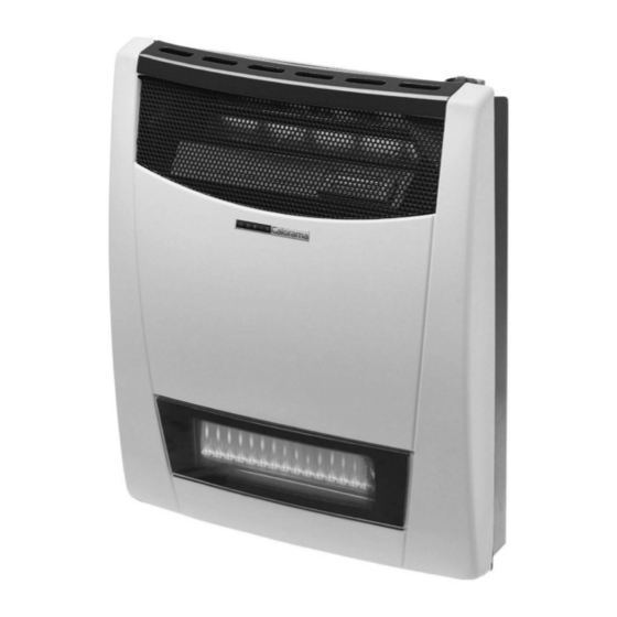
ORBIS DIRECT VENT ROOM
HEATERS
CALORAMA/COMFORT VIEW SERIES DIRECT VENT
WALL FURNACE
INSTALLATION AND OPERATING MANUAL
Complete instructions for safe installation, operation and servicing of units
manufactured for use with natural gas and propane liquefied petroleum gases.
ORBIS
WARNING: If the information in this manual
is not followed exactly, a fire or explosion
may result causing property damage,
personal injury or loss of life.
- Do not store or use gasoline or other flammable
vapors and liquids in the vicinity of this or any
other appliance.
- WHAT TO DO IF YOU SMELL GAS
- Do not try to light any appliance.
- Do not touch any electrical switch; do not use
any phone in your building.
- Immediately call your gas supplier from a
neighbor's phone. Follow the gas supplier's
instructions.
- If you cannot reach your gas supplier, call the
fire department.
- Installation and service must be performed by
a qualified installer, service agency or the gas
supplier.
COMFORTVIEW
ORBIS
CALORAMA
OWNER'S MANUAL
P/N CCV - MANUAL
CAUTION: Read these printed instructions
prior to starting the installation of this unit
ATTENTION: Heaters installed in the State
of Massachusetts must be installed by a
licensed plumber or gas fitter.
IMPORTED BY:
The Gas Appliance Company, Inc.
FLORIDA, US of A
www.orbisheat.com
Advertisement
Table of Contents

Summary of Contents for Orbis COMFORTVIEW
- Page 1 ORBIS DIRECT VENT ROOM HEATERS CALORAMA/COMFORT VIEW SERIES DIRECT VENT WALL FURNACE INSTALLATION AND OPERATING MANUAL Complete instructions for safe installation, operation and servicing of units manufactured for use with natural gas and propane liquefied petroleum gases. ORBIS COMFORTVIEW ORBIS CALORAMA OWNER’S MANUAL...
-
Page 2: Table Of Contents
Page 5 Propane / L.P. Gas odor Warning Page 5 CALORAMA/COMFORT VIEW (CCV) HEATER SPECIFICATIONS SECTION II – Installing Your Orbis ( CCV ) Direct Vent Space Heater Unpack the Heater Page 6 Locating the Orbis Calorama/Comfort View Series Space Heaters... -
Page 3: Section I - Introduction And Safety Information Introduction
INTRODUCTION AND SAFETY INFORMATION INTRODUCTION: Your purchase of the ORBIS Calorama/Comfort View I, II or III gas fired direct vent wall furnace will reward you with many years of satisfying safe operation. Read these instructions carefully. If you cannot understand them, or do not feel comfortable installing this unit, contact a qualified service technician or your gas supplier for assistance. -
Page 4: Safety Rules
3) MAINTAIN all clearances specified in the section entitled "Locating the Orbis Calorama/ Comfort View Series Heater." (See Fig. 1 and 2 and Table 2) 4) THIS APPLIANCE IS ONLY FOR USE WITH THE TYPE OF GAS INDICATED ON THE RATING PLATE. -
Page 5: Safety Information For Users Of Propane / L.p. Gas
WARNING: DO NOT USE THIS HEATER IF ANY PART HAS BEEN UNDER WATER. IMMEDIATELY CALL A QUALIFIED SERVICE TECHNICIAN TO INSPECT T HE APPLIANCE AND TO REPLACE ANY PART OF THE CONTROL SYSTEM AND ANY GAS CONTROL WHICH HAS BEEN UNDER WATER. SAFETY INFORMATION FOR USERS OF PROPANE / L.P. -
Page 6: Propane / L.p. Gas Odor Warning
WARNING: IMPROPER INSTALLATION, ADJUSTMENT, ALTERATION, SERVICE OR MAINTENANCE CAN CAUSE INJURY OR PROPERTY DAMAGE: REFER TO THIS MANUAL. FOR ASSISTANCE OR ADDITIONAL INFORMATION, CONSULT A QUALIFIED INSTALLER, SERVICE AGENCY OR YOUR GAS SUPPLIER. CALORAMA/COMFORT VIEW (CCV) SERIES HEATER SPECIFICATIONS CCVI CCVII CCVIII Model... -
Page 7: Unpack The Heater
LOCATING THE ORBIS CALORAMA/COMFORT VIEW SERIES SPACE HEATER S: When choosing a location for your ORBIS Calorama/Comfort View Series Direct Vent Wall Furnace, please remember that the Vent Kit supplied with the unit must be installed WITHOUT alteration, with the exception of cutting the vent tubes to length, as directed in these instructions. - Page 8 Mechanical draft vent terminal [see 7.8 (a)] Mechanical draft vent terminal [see 7.8 (b)] Less than 10 ft 4 ft minimum 3 ft minimum 12 in. minimum Direct vent terminal clearance Minimum clearance, C Input (Btu/hr) Clearance (in.) Forced air 10,000 or less inlet 10,001 to 50,000...
-
Page 9: Mounting Template
DUE TO HIGH OUTPUT TEMPERATURES AT THE TOP OF THE UNIT, THE UNIT SHOULD BE LOCATED OUT OF TRAFFIC AND AWAY FROM DRAP ERIES. 24” (610mm) 2” (51mm) 12” (304mm) 6.7” (170mm) Figure 2: Clearances for Mounting the Heater Itself TABLE 2 MINIMUM CLEARANCES REQUIRED FOR MOUNTING Model... -
Page 10: Combustible Materials
ORBIS Calorama/Comfort View Series Heater is installed BETWEEN THE WALL STUDS (See Figure 4). It is NOT permissible to cut the wall studs in order to install this unit. The wall studs can be used to mount the Calorama/Comfort View II and Calorama/Comfort View III units to the wall in order to provide a secure installation. - Page 11 TEMPLATE Figure 4: Unit Mounting Template Position Unit mounting positions Wall mounting positions Figure 5: Wall Mounting Plate (ALL MODELS)
-
Page 12: Section Iii - Vent, Wall Plate And Unit Installation
After ensuring that the location you have selected for the installation complies with the requirements outlined in this manual in the section titled "Locating the Orbis Calorama/Comfort View Series Space Heater," you should check to see that you have all of the following required tools to complete the job : Tape measureCarpenter’s levelDrill Screwdriver (Phillips &... -
Page 13: Vent And Wall Plate Installation
Begin installation by locating the wall studs on the inside wall of the structure. Use a stud locator or small finishing nail (repeatedly drive and remove a nail into the wall in the area of the stud until you find it). After you have found one stud, the inside edge of the other stud should be about 14 _ "... - Page 14 Figure 8: Vent Cap "ORBIS" Marking is Upright and Level Step 5 Insert the vent kit assembly through the outside hole into the inside of the structure. Ensure that the "ORBIS" lettering on the vent cap is level and upright. (See Figure 8).
-
Page 15: Connect Gas Piping
Connect Gas Piping: Connect the gas piping to the gas inlet of the valve on the right side of the unit. Gas piping connections require an approved pipe joint compound that must resist the action of Natural and Propane/LP Gas. Please refer to the cautionary remarks noted at the beginning of this manual. -
Page 16: Check For Gas Leaks
EXTERNAL REGULATOR L.P. ORBIS HEATER SUPPLY TANK GAS VALVE WITH BUILT-IN REGULATOR MANUAL SHUT-OFF VALVE TO BE INSTALLED GAS SUPPLY INLET DRIP LEG 3" MINIMUM (NOT TO EXCEED 13 IN.W.C.) Fig 9 – Guidelines for Gas Piping Connections (ANSI Z223.1) -
Page 17: Installing The Unit Cover
Installing the Unit Cover: Slide the heads of the two (2) bolts at the bottom of the front cover into the corresponding holes in the back cover (with the upper end of the front cover leaning about an inch forward), push the front cover in and down until the bolts lock into place. Slide the overhangs at the upper end of the front cover under the back cover and fix with the two (2) screws. -
Page 18: Adjusting The Thermostat
CAN CAUSE SEVERE BURNS AND/OR PROPERTY DAMAGE. Adjusting the Thermostat: The Orbis Calorama/Comfort View Series heater is equipped with a modulating thermostatic control for your comfort. The term "modulating" means that the gas flow to the burner is constantly adjusted either higher or lower depending on the temperature of the room. -
Page 19: Section Iv - Maintenance Instructions
SECTION IV MAINTENANCE INSTRUCTIONS Maintenance Instructions (General): As with all fuel burning appliances, it is important to conduct periodic maintenance functions that will allow for continued safe, efficient operation of the unit. We suggest that before each heating season, or at least once every year, you conduct the following MINIMUM service functions. - Page 20 Remove the gas control valve rod by removing the cotter pin. Disconnect both piezoelectric igniter cables from their connections to the heat exchanger. Remove the electrode ceramic. Remove the two (2) gas lines connecting the gas control valve to the pilot and main burner from both ends.
- Page 21 Figure 11: Flame Pattern for Pilot and Main Burner TO CLEAN OR CHANGE THE INJECTORS Remove the two (2) gas lines connecting the gas control valve to the pilot and main burner from both ends. Remove the main burner injector and the pilot injector. Clean the injectors with a soft bristled brush and air.
-
Page 22: Section V - Troubleshooting Guide Pages
SECTION V ORBIS CALORAMA/COMFORT VIEW (CCV) HEATER TROUBLESHOOTING GUIDE SOLUTION SYMPTOM POSSIBLE CAUSE 1. No action required: will stop Smoke or strange smell 1. Grease or oil on the heat on the first trial light up after a short period of exchanger. - Page 23 SOLUTION SYMPTOM POSSIBLE CAUSE Pilot will not stay lit. 1. Check the position of the knob 1. Gas control knob did not pop up. in the frame. Remove front cover and check movement of the gas control rod. Gas control valve may be jammed –...
- Page 24 SOLUTION SYMPTOM POSSIBLE CAUSE 7. Call your gas supplier. 7. Improper gas supply. Room will not maintain 1. Adjust thermostat to "HI" 1. Thermostat adjusted wrong . position and modulate down temperature. until a proper room temperature rate is attained. 2.
-
Page 25: Section Vi - Replacement Parts Guide Pages
SECTION VI REPLACEMENT PARTS GUIDE Orbis Calorama/Comfort View Series Gas System... - Page 26 DIAGRAM DESCRIPTION PART NUMBER OF PART NUMBER 1 (A) Front Cover Comfort View I CCV - 1001 1 (B) Front Cover Comfort View II CCV - 2001 1 (C) Front Cover Comfort View III CCV - 3001 1 (D) Front Cover Calorama I CCV - 4001 1 (E) Front Cover Calorama II...
-
Page 27: Section Vii - Limited Warranty Pages
No one is authorized to make any warranties on behalf of ORBIS/GASCO. It is expressly understood 2) No liability is assumed by ORBIS / GASCO for that the replacement warranty of GASCO shall be in removal or installation labor costs. - Page 28 FOR TECHNICAL ASSISTANCE OR TO PLACE AN ORDER FOR REPLACEMENT PARTS, PLEASE CONTACT YOUR GAS SUPPLIER / SERVICE TECHNICIAN OR APPLIANCES, SERVICES AND PARTS COMPANY, INC [ASAP] (INFORMATION BELOW) MANUFACTURED BY: ORBIS MERTIG SAIC YERBAL 1200 1607 VILLA ADELINA PROVINCIA DE BUENOS AIRES ARGENTINA IMPORTED BY: THE GAS APPLIANCE SUPPLY CO., INC.
-
Page 29: Section Viii - Blower Option Pages
SECTION VIII BLOWER OPTION You can use an optional blower kit with your heater and can be ordered thru your dealer. This kit can improve heat circulation in the room in which you installed your Calorama/Comfort View unit. Installation instructions: Remove the unit’s front cover to access the mounting point of the Temperature Activation Sensor on the upper right side of the unit, above the gas valve. - Page 30 BLOWER TEMPERATURE ACTIVATION SENSOR Figure 13: Blower Temperature Activator Sensor Installation REPLACEMENT BLOWER PARTS GUIDE DIAGRAM DESCRIPTION PART NUMBER OF PART NUMBER 1 (A) Blower kit Calorama/Comfort View I BK - 1 1 (B) Blower kit Calorama/Comfort View II BK - 2 1 (C) Blower kit Calorama/Comfort View III BK - 3...
Need help?
Do you have a question about the COMFORTVIEW and is the answer not in the manual?
Questions and answers