Table of Contents
Advertisement
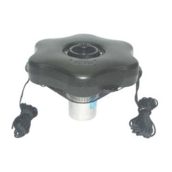
Owners Manual
Aerating Fountains
Important Safety. . . .
General Instructions. . . .
Cord Gauge Chart. . . .
Unit Specs. . . .
3400JF, 3400HJF Parts Included. . . .
3400JF, 3400HJF Assembly. . . .
4400JF, 4400HJF Parts Included. . . .
4400JF, 4400HJF Assembly. . . .
Mesh Screen Attachment. . . .
Nozzle Options. . . .
Installation Instructions. . . .
Control Panel Installation. . . .
C-25 Timer Control Instructions. . . .
C85 non-metallic Wiring Diagram. . . .
C85 / C95 non-metallic and 3 Phase Control Panel Timer. . . .
Maintenance Recommendations. . . .
Warranty Policy. . . .
Troubleshooting Tips. . . .
3400J Replacement Parts. . . .
4400J Replacement Parts. . . .
Customer Repair Form. . . .
Registration Information. . . .
C
Intertek
3020379
ANSI/UL 778, 5th Ed. 2010
CAN/CSA C22.2 No. 108-M89
UL 50, 11th Ed. 1995
3400JF & 3400HJF
4400JF & 4400HJF
Contents
Kasco Marine, Inc.
800 Deere Rd.
Prescott, WI 54021
PH (715) 262-4488
FAX (715) 262-4487
www.kascomarine.com
pg2
pg2
pg3
pg3
pg4
pg4
pg6
pg7
pg8
pg9
pg10
pg11
pg12
pg14
pg15
pg16
pg17
pg18
pg20
pg21
pg22
pg24
Rev. 05/22/12
Advertisement
Table of Contents

Summary of Contents for Kasco Aeration 3400JF
- Page 1 General Instructions..Cord Gauge Chart..Unit Specs..3400JF, 3400HJF Parts Included..3400JF, 3400HJF Assembly..4400JF, 4400HJF Parts Included..4400JF, 4400HJF Assembly..
-
Page 2: General Instructions
THANKS PFD. (Personal Flotation Device) We at Kasco Marine, Inc. would like to both thank and • The fountain is supplied with an internal ground- congratulate you on your purchase of the JF model ing conductor and a grounding-type attachment aerating fountain. -
Page 3: Cord Gauge Chart
3400JF model Fountain with a 2 Year War- tant to store them upside down if they are going to be ranty. This warranty covers any and all manufactur- sitting for long periods of time. Units that sit upright... -
Page 4: Table Of Contents
3400JF, 3400HJF Parts Included Set of 5 Interchangeable Nozzles (5) 1. 3/8” x 2.25” bolt (1) 3400JF Aerating Fountain (Unit with cord or unit 2. 3/8” x 4” bolt (1) with Disconnect) (1) 3. Linden Nozzle (1) Float (with two 50’ mooring ropes attached) (1) 4. -
Page 5: Bottom Screen
STEP TWO STEP SIX Set motor housing upright (stainless steel can down) See “Mesh Screen Attachment” section before con- on a fl at surface. necting the bottom screen to the fl oat. Turn secured assembly upside down so the top of the fl oat (logo STEP THREE side) is face down on the fl... -
Page 6: X 1-3/4" Hex Head
4400JF, 4400HJF Parts Included if installed from the bottom or top side of the opening. It will not fi t if installed from side of opening. Use the 4400JF Aerating Fountain (Unit with cord or unit Nylon Cable Tie included to secure the power cord to with Disconnect) (1) a molded hole in the fl... -
Page 7: Linden
Set of 5 Interchangeable Nozzles (5) 1. 3/8” x 2.25” bolt (1) Rest the fl oat on the cage top ring. 2. 3/8” x 4” bolt (1) STEP THREE 3. Linden Nozzle (1) 4. Sequoia Nozzle (1) Ensure correct alignment by twisting the fl oat gently 5. -
Page 8: Mesh Screen Attachment
STEP FIVE It will not fi t if installed from side of opening. Use the See “Mesh Screen Attachment” section before con- Nylon Cable Tie included to secure the power cord to necting the bottom screen to the fl oat. Turn secured a molded hole in the fl... - Page 9 (marked C2 on the top rim) and the 3/8” x 4” bolt. 2 inch overlap Model Height Width 3. Flip mesh and screen assembly over and use re- 3400JF/HJF 6’ 16’ maining cable ties to secure mesh to small bottom 4400JF/HJF 7.5’ 25’...
-
Page 10: Installation Instructions
The Linden nozzle (marked L inside one of the fi ns) The Sequoia nozzle is not marked and uses the shorter uses the 3/8” x 4” bolt. 3/8” x 2.25” Model Height Width 3400JF/HJF 6’ 18’ 4400JF/HJF 8’ 25’ Model... -
Page 11: Control Panel Installation
STEP THREE Follow all local and national electrical codes for this installation and Consult a qualifi ed electrician or service person if needed. (For 120V Installations) Plug the aerator cord into the C-25 outlet labeled “UNIT”. If lights are included, plug the Transformer cord into the C-25 outlet labeled “LIGHT”. -
Page 12: C-25 Timer Control Instructions
should be stripped back at least 3inches. Follow the Record the following data while the Aerator is connection diagram for terminating these three wires operating in the water under load: to the terminal blocks in the control panel. Voltage: Black connects to Terminal White connects to Terminal #5 L1-L2 ________ Green connects to Terminal... - Page 13 LOCKS AND RE-MAINS DEPRESSED AFTER PRES- SURE HAS BEEN REMOVED. DANGER: IF RESET BUTTON DOES NOT POP OUT, IF TEST LAMP REMAINS LIT WHEN RESET BUTTON DOES POP OUT, OR IF THE G.F.C.I. FAILS TO RE- SET PROPERLY, DO NOT USE TIMER! CONTACT A QUALIFIED SERVICE TECHNICIAN! Failure to use the C-25 with Kasco Fountains will void the warranty and cause the Fountain to not be listed to UL and...
- Page 14 C85 non-metallic Wiring Diagram...
-
Page 15: C85 / C95 Non-Metallic And 3 Phase Control Panel Timer
C85 / C95 non-metallic and 3 minutes for each tripper on the 24-Hour dial. When Phase Control Panel Timer the tripper is pushed to the inside, the switch is in the “OFF” position. TIME CLOCK SETTING PROGRAMMING WITH MANUAL OVERRIDE SWITCH To set the current time, turn the inner dial clockwise. -
Page 16: Maintenance Recommendations
The power cord should be inspected for motor assembly and seals will wear out over time damage and you should call Kasco Marine at 715- (similar to brake pads on a car). Replacement of the 262-4488 for further instructions or email Kasco at seals and a change of oil after three years may add returns@kascomarine.com. -
Page 17: Warranty Policy
The Kasco Marine, Inc. obligation Kasco Marine will have a record of the purchase and under this warranty is limited to replacing or repairing will be able to determine whether or not the unit still free of charge any defective part within the warranty caries warranty coverage. -
Page 18: Troubleshooting Tips
Any expedited shipping method for the return of the problem occurs, please double check the assembly and unit is at the customer’s expense. Kasco Marine will installation instructions as well as the instructions for return units repaired under warranty at our expense via the proper control panel. - Page 19 you are noticing these symptoms, the unit should be unplugged immediately because the Thermal Overload will continue to turn on and off until it burns out and damages the motor. The unit should be unplugged and taken out of the water to fi nd the cause of the problem. The problem could be one of many, such as, low water levels, build-up on the unit to prevent heat dissipation, something inhibiting the free rotation of the shaft, etc.
- Page 20 3400J Replacement Parts 3400J Replacement Parts...
- Page 21 4400J Replacement Parts 4400J Replacement Parts...
-
Page 22: Customer Repair Form
3 years depend- ing on use. • Address your Repair to Kasco Marine, Attn: Repairs (or to your Authorized Repair Center. • Shipping to Kasco or an Authorized Repair Center is paid for by the customer. -
Page 24: Fax (715)
Registration Information Please register your fountain online at: www.kascomarine.com (Under the Technical Tab) Also fi ll in the information below and keep for your records. Model # (Ex. 3400JF)_______________________________ Serial # (Ex. 8001J31725)______________________________ Purchase Date:_____________________ Purchased From:___________________________________ Registration Date: ___________________________ Kasco Marine, Inc.
Need help?
Do you have a question about the 3400JF and is the answer not in the manual?
Questions and answers