Table of Contents
Advertisement
Quick Links
Installation & Operation Manual
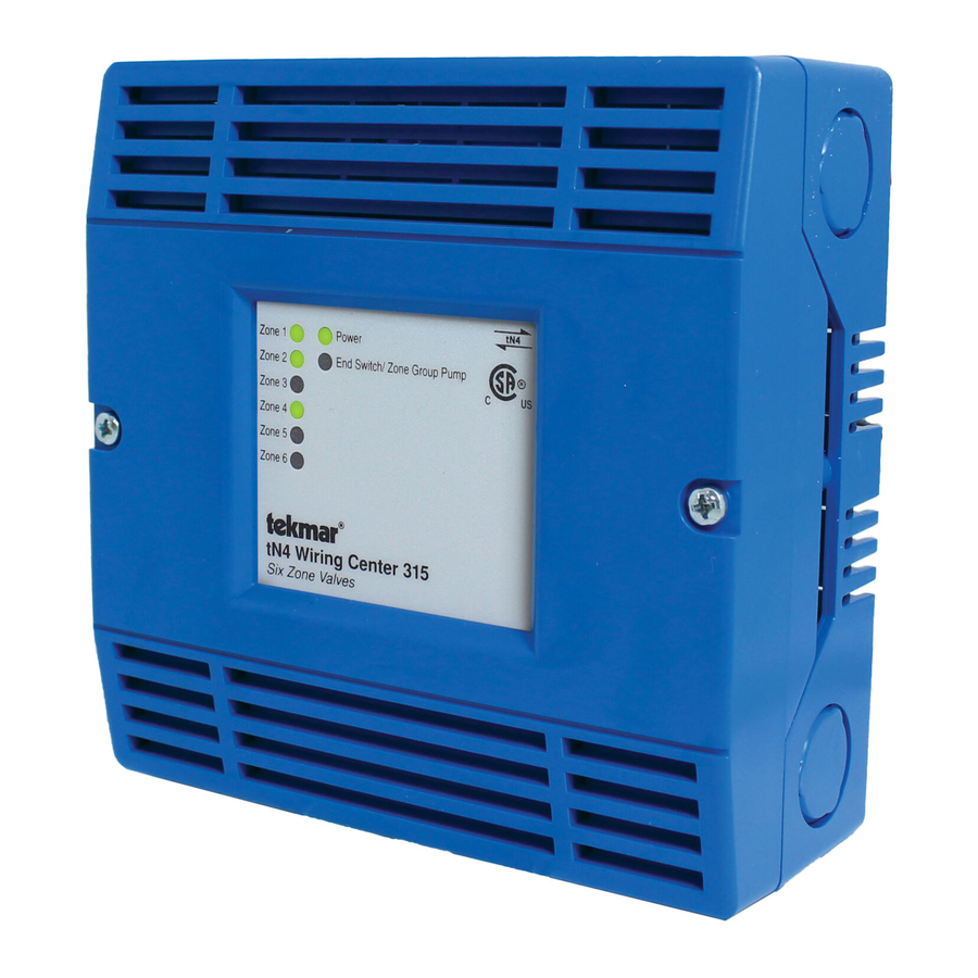
tN4 Wiring Center 315
Introduction
®
The tekmarNet
4 (tN4) Wiring Center 315 is designed to
operate up to six zone valves in a hydronic heating system.
It can be mounted near a remote zone manifold, providing a
convenient location to wire both thermostats and zone valves
while only requiring two wires to be run back to the mechanical
room. When combined with tekmarNet
devices communicate to provide a synchronized end switch
that reduces cycling of equipment. A zone group pump
relay is also available to switch a pump.
Power
End Switch/ Zone Group Pump
tN4 Wiring Center 315
Six Zone Valves
®
4 Thermostats, all
Features
•
•
•
•
•
•
•
Benefi ts
•
•
•
Note
•
1 of 12
Six 24 V (ac) powered zone outputs
®
For use with tekmarNet
4 Thermostats
tN4 expansion terminals
Isolated end switch
Zone group pump relay
External diagnostic LEDs
CSA C US Certified for use in USA and Canada
Simple, convenient wiring location
Compact enclosure for flexible installation
Reduce equipment cycling when combined with
tekmarNet
®
4 Thermostats
Not for use with tekmarNet
D 315
04/11
Zoning
Replaces: 04/09
®
2 Thermostats
© 2011
D 315 - 04/11
Advertisement
Table of Contents

Summary of Contents for Tekmar D 315
- Page 1 Simple, convenient wiring location • Compact enclosure for flexible installation • Reduce equipment cycling when combined with tekmarNet ® 4 Thermostats Note ® • Not for use with tekmarNet 2 Thermostats 1 of 12 © 2011 D 315 - 04/11...
-
Page 2: Table Of Contents
• 14 AWG solid wire (line voltage connections) • (2) wire nuts • tekmar 009 (24 V (ac) transformer) • 18 AWG LVT solid wire (low voltage connections) • Cable or conduit connectors Power Required -- -- - ------ - ----- - --- -- - - -- -- - - -- - -- -- - --- -- -- - --- -- - -- --- -- - -- --- -- - - -- --- -- -- - - -- - -- - - --- --- ----- ---- ----- ---- - - - - - - - - - - - - - - - - - - - - - - - - - - - - - - - - - - - - - - - - - - - - - - - - - - - - - - - - - - - - •... -
Page 3: Physical Dimensions
Zone Group Pump (if applicable) All line voltage wire connections are recommended to be pulled inside a flexible or solid conduit. Always follow proper wiring practices, building and electrical codes for your jurisdiction. 3 of 12 © 2011 D 315 - 04/11... -
Page 4: Sizing The Transformer
40 VA, and includes an in-line fuse the control. This total load must not exceed 98 VA. Multiple to protect the transformer and control. tekmar Transformer 009’s can be wired together to increase total VA capacity. In order to correctly size the external transformer, all loads connected to the control must be taken into account. - Page 5 Install the thermostat to the appropriate R and W ter- • If required, use the X X End Switch terminals to switch minals on the 315. 24 V (ac) to power a demand on a tekmar outdoor reset control. 5 of 12 © 2011...
-
Page 6: Testing The Control Wiring
See the thermostat installation manual for should be 0 V (ac). details. • When teh zone group pump LED is on, the voltage should be between 103.5 to 126.5 V (ac). © 2011 D 315 - 04/11 6 of 12... -
Page 7: Applications
4 Expansion to Building Control A315-1 Description: tN4 Wiring Center 315, six tekmarNet ® 4 Thermostats, and six zone valves wired to a tekmar System Control 420 and 335, which controls the boiler, primary pump and DHW pump and six other zones. tekmarNet ®... - Page 8 Description: tN4 Wiring Center 315, six tekmarNet ® 4 Thermostats, and six zone valves wired into a powered boiler demand input on a device such as a tekmar Boiler Control 260 which controls the primary pump and DHW pump. ® tekmarNet...
- Page 9 Zone 5 Zone 6 to boiler enable (T-T) 24 V (ac) Transformer 009 Zone Valves (Z1 to Z6) (black) Zone Group Pump (red) Power L to pump grounds 115 V (ac) 9 of 12 © 2011 D 315 - 04/11...
-
Page 10: User Interface
® components: vacations and holidays • House Controls 400, 401, 402, 403 - Provides boiler and • tN4 Setpoint Control 161, 162 - Control hot tubs, pools DHW control and more © 2011 D 315 - 04/11 10 of 12... -
Page 11: Relay Outputs
This can provide a boiler demand on. Power is then supplied to the appropriate zone output to a tekmar reset control, or provide a boiler enable to a as indicated by the LED. boiler’s TT terminals. -
Page 12: Technical Data
Representative. tekmar Control Systems Ltd., Canada, tekmar Control Systems, Inc., U.S.A. Head Offi ce: 5100 Silver Star Road, Vernon, B.C. Canada V1B 3K4, 250-545-7749, Fax. 250-545-0650 Web Site: www.tekmarcontrols.com Product design, software and literature are Copyright ©...
Need help?
Do you have a question about the D 315 and is the answer not in the manual?
Questions and answers