Table of Contents
Advertisement
Quick Links
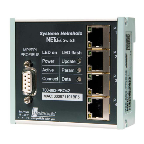
Ethernet Gateway for MPI/PPI/PROFIBUS
700-883-PRO42
User Manual
Edition 2 / 29.03.2010
HW 1-1, FW 2.30 and higher
Order number of manual: 900-883-PRO42/en
Systeme Helmholz GmbH
Hannberger Weg 2
91091 Großenseebach
Germany
Phone: +49 9135 7380-0
Fax: +49 9135 7380-110
E-Mail: info@helmholz.de
Internet: www.helmholz.de
Advertisement
Table of Contents

Related Manuals for NetLink 700-883-PRO42

Summary of Contents for NetLink 700-883-PRO42
-
Page 1: User Manual
Ethernet Gateway for MPI/PPI/PROFIBUS 700-883-PRO42 User Manual Edition 2 / 29.03.2010 HW 1-1, FW 2.30 and higher Order number of manual: 900-883-PRO42/en Systeme Helmholz GmbH Hannberger Weg 2 91091 Großenseebach Germany Phone: +49 9135 7380-0 Fax: +49 9135 7380-110 E-Mail: info@helmholz.de... - Page 3 All rights are reserved, including those of translation, reprinting, and reproduction of this manual, or parts thereof. No part of this manual may be reproduced, processed, copied, or transmitted in any way whatsoever (photocopy, microfilm, or other method) without the express written permission of Systeme Helmholz GmbH, not even for use as training material, or using electronic systems.
- Page 4 Revision history of this document: Edition Date Revision 18.08.2009 First Edition Change cross-cable in the scope of supply, new Web Interface fea- 29.03.2010 tures added...
-
Page 5: Table Of Contents
Installation of the driver software Introduction System requirements Running the installation setup 4.3.1 Adding the interface to the PG/PC interface 4.3.2 Selecting the required interface parameterization Configuration via the NETLink-S7-NET Driver Bus settings 5.1.1 5.1.2 PROFIBUS configuration 5.1.3 PPI configuration Local connection (TCP parameterization) ®... - Page 6 5.3.2 Version information Diagnostics 5.4.1 Bus members 5.4.2 Bus parameters Teleservice ® The Tool: ‘NETLink PRO Family Configuration’ Possibilities of the Web Interface Home page Status page Configuration page Security page Observing variables RFC1006 Function (S7-TCP/IP) Bus Parameters in Single Master Operation...
- Page 7 11.2.4 Power supply socket 11.3 Further Documentation 11.4 Information in the internet 11.5 Address conversion table Glossary ® NETLink Switch...
-
Page 8: Safety Information
Hazard, general or specific Danger of electric shock General ® NETLink Switch is only used as part of a complete system. The operator of a machine system is responsible for observing all safety and accident prevention regulations applicable to the applica- tion in question. -
Page 9: Restriction Of Access
This manual is addressed to anyone wishing to configure, use, or ® install NETLink Switch. ® The manual tells the user how to operate NETLink Switch and ex- During configuration, plains the signaling functions. It provides the installing technician safety and accident pre- with all the necessary data. -
Page 10: Installation And Mounting
NETLink Switch can be installed in any position. Minimum clearance Minimum clearances must be observed because • Then it is possible to insert and remove NETLink ® Switch with- out having to remove other system components. • There is enough space to connect existing interfaces and other contacts using standard commercial type accessories. -
Page 11: System Overview
Switch with the pro- ® grammable controller is to be connected to the front of NETLink Switch. In case of a branch line it is to be executed actively (acces- sories, see chapter 3.5). When a node is integrated in the bus, the connection can be carried out via a common PROFIBUS plug (ac- cessories, see chapter 3.5). -
Page 12: Connections
Switch is at the beginning or end of a bus segment. If this is ® not the case, the switch position must be OFF. If NETLink Switch is to be operated with a branch line, the latter has to be executed as ‘active line’... -
Page 13: Items Supplied
Switch ready to run The NETLink has the • CAT5 TCP cable (cross-over) with a length of 3 meters IP address 192.168.4.49 on de- • CD with NETLink-S7-NET driver, additional info’s livery from the factory. • Manual (German/English) Accessories 3.5.1... -
Page 14: Profibus Accessories
Atex license, with PG, Ex-Zone 2 700-973-0BB12 PROFIBUS plug diagnostics without PG 700-972-7BA12 PROFIBUS plug diagnostics with PG 700-972-7BB12 PROFIBUS FLEXtra profiPoint 700-972-1AA02 PROFIBUS FLEXtra twinRepeater 700-972-2AA02 PROFIBUS Compact Repeater 700-972-0RB12 Dismantling tool for PROFIBUS 700-972-6AA00 ® NETLink Switch... -
Page 15: Installation Of The Driver Software
System requirements A PC with a 32-bit Windows operating system is required to oper- ate the NETLink-S7-NET driver at the PU end. The Windows XP (SP3) and Windows Vista operating systems can be used. A further requirement is the existence of a Simatic engineering tools, such as STEP7, Version 5.1 and higher or STEP7-Micro/Win... -
Page 16: Adding The Interface To The Pg/Pc Interface
After you have started ‘Set PG/PC Interface’ in the Control Panel, click the ‘Select…’ button there. This opens the ‘Install/uninstall interface’ dialog box. After you have selected the entry ‘NETLink-S7-NET PRO family’ from the left-hand list, click the ‘Install-->’ button. ®... -
Page 17: Selecting The Required Interface Parameterization
The selection list for the interface parameter sets now contains an additional three items for NETLink PRO Family. All relevant settings of a NETLink-S7-NET driver can be made via the "Properties" access field. With the button ‘Diagnostics...’ it is possible to show the nodes connected to the bus and the parame- ters the bus is working with. -
Page 18: Configuration Via The Netlink-S7-Net Driver
® The bus configuration is passed to the NETLink Switch during the runtime of the NETLink-S7-NET driver and is not stored in the device. ® It is possible to use the NETLink Switch without specifying bus- ®... -
Page 19: Mpi
Any value between ‘0’ and ‘31’ can be specified for the station ad- dress if this address does not yet exist on the bus. The local timeout of the NETLink-S7-NET driver can be param- eterized in the station-related settings. If the driver does not re- ceive a response to a request within the set timeout, a communi- cation error is signaled to the Simatic application. -
Page 20: Profibus Configuration
Section 5.1.1, PROFIBUS also has pa- rameter field for selecting the bus profile and bus parameters. ® If the NETLink Switch is the only active station on the PROFIBUS, it operates in so-called single-master mode, i.e. it gen- erates the token cycle with the set bus parameters. - Page 21 • Always set the PROFIBUS parameters that are set in the cur- rently used programmable controller (see current STEP7 pro- ject). In order to simplify these procedures, it makes sense to use of the auto baud function under PROFIBUS. ® NETLink Switch...
- Page 22 ‘Cyclic distribution of the bus parameters’ function is acti- vated in the programmable controller used. The screenshot above of a hardware configuration of a randomly chosen PROFIBUS CPU shows where to find the switch for cyclic distribution of the bus parameters. ® NETLink Switch...
-
Page 23: Ppi Configuration
• Parameterization via ‘Set PG/PC interface Existing stations can be reparameterized using the ‘Change’ button • Parameterization via the ‘NETLink PRO Family configuration’ tool (see Section 6). • Parameterization via the web interface of the NETLink ® Switch (see Section ®... -
Page 24: Creating A Station
5.2.1 Creating a station The ‘New’ button takes you to an input dialog box in which you ® can store the known IP address of an existing NETLink Switch and any name for easier assignment. The NETLink has the IP address 192.168.4.49 on... - Page 25 This station can also be saved with ‘OK’ and is then available. ® If you do not want the name that is stored in the NETLink Switch to be the same as the station name, you can overwrite the station name (e.g. replacing the name ‘Helmholz_test’ with the name ‘Workshop’...
-
Page 26: Setting Tcp Parameters
This completes parameterization of the driver. ® It may now be necessary to adapt the NETLink Switch to the situation in the existing TCP/IP network. 5.2.2 Setting TCP parameters To change the TCP parameters, select the station in question and open the following dialog box with the ‘Edit’... -
Page 27: Operation Without The Dhcp
The ‘Parameterize NETLink …’ button takes you to a new input form that already contains the current parameters of the NET- ® Link Switch: ® If no NETLink Switch can be accessed via the stated IP address, the following message will appear: This message can have two causes: •... -
Page 28: Dhcp
Section 7 provides more detailed information about what you can do with the web interface. • Changing the password: Here you can change the actual password. ® It is only possible to change the configuration of the NETLink Switch with the password. ® NETLink Switch... -
Page 29: Options Of The Driver
Switch in this case, too. Options of the driver Under the options of the NETLink-S7-NET driver, it is possible to set the language of the output and help texts of the driver. It is also possible to read out the version numbers of the driver files used. -
Page 30: Diagnostics
MPI and PROFIBUS. 5.4.2 Bus parameters If it is possible a list of all bus parameters will be displayed by clicking the button ‘Read.’ The possibility to detect the bus parameters depends on the parameterization of the PG/PC Interface. ® NETLink Switch... -
Page 31: Teleservice
Administrator can ensure that it is not visible/usable from outside. Disadvantage: Network administrators must parameterize routers and firewalls between the communicating nodes. • Use of a dial-up router (e.g. NETLink ® Router) Advantage: relatively simple to implement if a phone connection is available. -
Page 32: The Tool: 'Netlink
An extended function enables direct parameterization across net- work boundaries. To do this, activate the radio button and enter ® the known IP address of the NETLink (the example includes the optional address of the port – separated by a colon) in the empty field. -
Page 33: Possibilities Of The Web Interface
Switch can be opened with any standard browser (e.g. Internet Explorer, Firefox, Opera, etc.) The web interface is intended to support the user intuitively with ® information and configuration tasks. The NETLink Compact has the IP ad- dress 192.168.4.49 on Home page delivery from the factory. -
Page 34: Status Page
The status page, accessible via a link on the home page, provides the user with information without allowing unauthorized recon- ® figuration of the NETLink Switch. The page provides general information (e.g. firmware version, number of possible connections, etc.), and specific information (baud rate, active stations, DHCP status, etc.). - Page 35 To make use of this function, “Go Online” must be acti- ® vated for the NETLink Switch on the bus system. This can be done with an engineering tool such as STEP7 or by using the “Go Online” button on the status page. This function can also be switched on permanently on the “Basic Configuration”...
- Page 36 The result is entered in line: List of passive stations. ® NETLink Switch...
- Page 37 V2.240 Serial number e.g. T00008797 MAC address e.g. 00:06:71:19:22:5D ® This shows the freely selectable name of the NETLink Device name Switch, if a name has been assigned. Bus-specific parameters: ® If the NETLink Switch is active on the bus, this is the Own station address device’s own station address.
-
Page 38: Configuration Page
The configuration page, accessible via a link on the home page, is a configuration interface for the user. The default user name is Before this page is opened, the user name (default: NETLink “NETLink Switch” Switch, if no user-defined user name is entered) and the password The default password is (admin if no user-defined password has been set) must be entered. - Page 39 As soon as you have answered the security query, you will have write access to all parameters. ® NETLink Switch...
- Page 40 DHCP timeout elapses. In addition to the standard port, a further freely ® Alternative NETLink Port selectable port can be stored here in the NETLink Switch. Automatic fetching of address parameters from a DHCP ON/OFF DHCP server ON or OFF.
-
Page 41: Security Page
In this way, manipulation of the CPU sequential program is ruled out. ® This assumes, of course, that the access data for the NETLink Switch web interface are secure. Notice deviation by usage Attention: To prevent their use by unauthorized persons, any of proxy servers. - Page 42 You may then be shown which inputs are incorrect and what correct input would look like at this point. If all entries are consistent, the changes are displayed again as ® they will now be stored non-volatile in the NETLink Switch when you click the ‘Store’ button again. ®...
-
Page 43: Observing Variables
NETLink Switch. TCP/IP address Seventh and eighth IP addresses that are allowed ® 7 and 8 to access the NETLink Switch. TCP/IP address Ninth and tenth IP addresses that are allowed to ® 9 and 10 access the NETLink Switch. - Page 44 ‘cyclic fetch’ for a permanent online query. With ‘Save Configuration’, it is possible to store the screen form you have created with all the variables and their descriptions in ® the NETLink Switch. ® NETLink Switch...
- Page 45 NET- ® Link Switch. Moreover, data exchange via MPI/PB and/or RFC 1006, the ‘Observe Variables’ action has the lowest priority. The update time in the Web interface therefore depends on the con- current bus load. ® NETLink Switch...
-
Page 46: Rfc1006 Function (S7-Tcp/Ip)
Trouble- The following software packages with RFC1006 support have so shooting and possibly in far been tested in conjunction with the NETLink products: other relevant documenta- tion • WinCC V6.0/V7.0 (Siemens AG) • WinCC flexible 2005/2007/2008 (Siemens AG) •... -
Page 47: Bus Parameters In Single Master Operation
The bus address with which the NETLink Switch signs onto the bus is entered in field “NETLink MPI/PB Address”. The value for this address may be anywhere in the range 0 through 126. It is a precondition for this that the selected address is not larger than the HAS (highest station address) and is not al- ready being used for another device on the bus. -
Page 48: Addressing (Rack/Slot Mode On/Off)
Switch is a point-to-multipoint communication ® ® adapter (‘PC to NETLink Switch ’ on the one hand and ‘NETLink Switch to many bus stations’ on the other hand), it was necessary to implement different addressing methods to permit all commu- nication variations. -
Page 49: Addressed Mode
Remote TSAP. The formula Rack * 32 + Slot = Address can be used for simplicity. 9.2.2 Rack/slot mode In rack/slot mode, it is possible to access specific modules of the automation system. ® NETLink Switch... -
Page 50: Example Of Configuration For Wincc V7.0
(see Section 9.3.1) and again in rack/slot mode (see Section 9.3.2). 9.3.1 Using addressed mode ® For the basics of addressed mode at the NETLink Switch end, see Section 9.2.1 To parameterize a RFC1006 link in a WinCC project, a new TCP/IP link must first be created in the ‘SIMATIC S7 PROTOCOL... - Page 51 Here, this connection is called ‘NETLink.’ A click on ‘Properties’ takes us to a setting form in which the IP ® address of the NETLink Switch and the rack/slot combination of the destination have to be entered. ® The NETLink PRO Com- ®...
- Page 52 ‘New variable…’. In the properties window of the variable, which was named ‘MB0_over_NETLink’ in this case, we can now select the type of variable by clicking the ‘Select’ button. Marker byte 0 is configured here. ® NETLink Switch...
-
Page 53: Use Of Rack/Slot Mode
CPUs. 9.3.2 Use of rack/slot mode ® For the basics of rack/slot mode at the NETLink Switch end, see Section 9.2.2. To parameterize a RFC1006 link in WinCC, a new TCP/IP link must first be created in the ‘SIMATIC S7 PROTOCOL SUITE.’... - Page 54 Here, this connection is called ‘NETLink.’ A click on ‘Properties’ takes us to a setting form in which the IP ® address of the NETLink Switch and the rack/slot combination of the destination have to be entered. ® The NETLink PRO Com- ®...
- Page 55 ‘New variable…’. In the properties window of the variable, which was named ‘MB0_over_NETLink’ in this case, we can now select the type of variable by clicking the ‘Select’ button. Marker byte 0 is configured here. ® NETLink Switch...
- Page 56 The following screenshot shows that a variable named ‘MB0_over_NETLink’ now exists under the ‘NETLink’ connection. If this variable is now included in the initial screen of the WinCC project, for example, a connection will be established to the CPU ®...
-
Page 57: Troubleshooting
The default password A: If no user name and/or password were/are specified, the de- is ‘admin.’ fault user name ‘NETLink Switch’ and the default password ‘admin’ are applied. Q: Once the configured PROFIBUS slaves have been added on my ®... - Page 58 Q: The setting dialog boxes are not appearing in the Simatic Man- ager: A: Please note that after initial installation the NETLink-S7-NET driver must be added to the PG/PC interfaces. Make sure you had administrator rights during installation. Re- boot your PC after installation if prompted to do so.
- Page 59 = ON) and have specified address 2 for my existing CPU in the Web interface in ‘Fix destination address for R/S mode.’ ® Although NETLink Switch online is active (active LED lights up), my visualization system tells me that no link can be established.
- Page 60 IP address on ® the fixed NETLink Switch port 7777 from the Internet. To be able to address the devices from the Internet despite this, a ® ‘public’ port is configured in the router for each NETLink Switch. ® NETLink Switch...
- Page 61 For that reason the “Internet Teleservice” option has been installed ® in the SHS7-NET driver, with which the port of a NETLink Switch configured in the router can be set. This configuration can be made in the ‘Station’ dialog box.
-
Page 62: Appendix
5 V DC for bus termination (looped through) 24 V DC for power supply (looped through) RxD / TxD-N receive / transmit data-N unused 11.2.2 Assignment of the Ethernet interface (host interface) Connector Signal Meaning transmit data transmit data ® NETLink Switch... -
Page 63: 11.2.3 Function Overview Of Internal Switch
• Extended NETLink functions - Project-specific interface • Communication with OPC, SCADA, HMI - Application exam- ples with RFC 1006 • NETLink WebService – Application examples and software • Extended NETLink functions – CPU-to-CPU communication 11.4 Information in the internet http://www.helmholz.de... -
Page 64: Address Conversion Table
2 25 0259 0279 021A 023A 2 26 025A 027A 021B 023B 2 27 025B 027B 021C 023C 2 28 025C 027C 021E 023D 2 29 025D 027D 021F 023E 2 30 025E 0220 023F 2 31 025F ® NETLink Switch... -
Page 65: Glossary
Gateway This is a machine that works like a router. Unlike a router , a gateway can also route data packets from different hardware networks. ® NETLink Switch... - Page 66 Port These are address components that are used in network protocols to assign the correct protocols to data segments, also using port forwarding. Port The passing on of requests to ports via a network. forwarding ® NETLink Switch...
- Page 67 Server A device that provides special services at the request of clients. ® Single Only one master is connected to the system. The NETLink family mem- master bers WLAN, Switch, and PRO Compact can also act as single masters Slave A station that is only permitted to exchange data with the master if re- quested to do so by the latter.
- Page 68 “Uniform Resource Locator,” denotes the address at which a service can be ® found in the Web browser. In this manual, the IP address of the NETLink Switch is usually entered as the URL. Virtual Private Network. Logical links, called tunnels, are established iva existing unsecured networks.
Need help?
Do you have a question about the 700-883-PRO42 and is the answer not in the manual?
Questions and answers