Table of Contents
Advertisement
Quick Links
Advertisement
Chapters
Table of Contents
Troubleshooting

Related Manuals for Digital Link DL3800 DS1

Summary of Contents for Digital Link DL3800 DS1
- Page 1 DL3800 DS1 Inverse Multiplexer User Guide Part 098-10380-01 Rev J February 1999...
- Page 2 IABILITY All claims for breach of the foregoing warranty shall be deemed waived unless notice of such claim is received by Digital Link during the applicable warranty period and unless the items claimed to be defective are returned to Digital Link within thirty (30) days after such claim. Failure of Digital Link to receive written notice within the speciÞc period shall constitute a...
- Page 3 Digital Link shall not be liable for failure to perform its obligations if such results directly or indirectly from, or is contributed to by, any act of God or of buyer; riot; Þre; explosion; accident; ßood; sabotage; epidemics; delays in transportation; lack of or inability to obtain raw materials, components, labor, fuel or supplies;...
- Page 4 If they do, you will be notiÞed in advance to give you an opportunity to maintain uninterrupted telephone service. DL3800 DS1 Inverse Multiplexer User Guide—February 1999...
- Page 5 Malfunction of the equipment: In the event this equipment should fail to operate properly, disconnect the unit from the telephone line. Try using another FCC approved telephone in the same telephone jack. If the trouble does not persist and appears to be with this unit, disconnect the unit from the telephone line and discontinue use of the unit until it is repaired.
- Page 6 DL3800 DS1 Inverse Multiplexer User Guide—February 1999...
-
Page 7: Table Of Contents
Table of Contents Audience xvii Organization xvii Conventions xviii Symbols xviii Typography Digital Link Technical Support Returning a Unit Send Us Your Comments Document Change Record Chapter 1, Quick Install Guide Purpose Configuration Equipment Needed Setup Terminal Log on Terminal Configuration... - Page 8 DL3800 System Features DL3800 System Benefits Application Chapter 3, Installation DL3800 Installation Procedure Mounting The DL3800 Rack Mounting Desk Operation And Stacking Power Cables And Connections AC Power Connection DC Power Connection T1 Network Connection DTE Cable And Connection ASCII Terminal and SNMP Connection Direct Connection Modem Connection Telnet Connection...
- Page 9 DTE Configuration 4-16 Network Configuration 4-18 Network Thresholds 4-23 Save Configuration 4-24 System Utilities 4-24 Software Download 4-25 Software Download Options 4-27 RAM Software Options 4-28 Delete Entire Unit Configuration (revert to factory config) 4-29 Login Configuration 4-30 SNMP Configuration 4-33 In-Band SNMP to Remote 4-36...
- Page 10 Top Menu Select Remote/Select Local Display Menu Node (Common Equipment) Status DTE Status NET (1-8) Status NET (1 through 8) Statistics Test Menu 5-11 DTE Tests 5-13 DTE/NET Loopback 5-13 Network Tests (1 through 8) 5-14 Payload Loopback 5-14 Line Loopback 5-15 Local Loopback 5-15...
- Page 11 External Clock Interface DTE Interface COMM Port NMS Port (SNMP) Front Panel Diagnostics Power Environmental Physical /Connectors Appendix B, Pinouts Terminal Connection DTE Connectors T1 Network Pin Assignments DB-25 to DE-9 Adapter Pinouts External Clock Connector Pin Assignments DTE Clock Rates Appendix C, Factory Default Settings Table of Contents...
- Page 12 Table of Contents -xii...
- Page 13 List of Figures Figure 1-1 The DL3800 DS1 Inverse Multiplexer Figure 2-1 DL3800 Inverse Multiplexer Figure 2-2 DL3800 Functional Schematic Figure 2-3 Typical Application for DL3800 Figure 3-1 DL3800 Rear Panel Figure 4-1 INVERSE MULTIPLEXER MAIN MENU Figure 4-2 Main Menu with remote unit selected...
- Page 14 Figure 4-12 Network Thresholds ConÞguration 4-23 Figure 4-13 SYSYTEM UTILITIES MENU Figure 4-25 Figure 4-14 SOFTWARE DOWNLOAD MENU 4-25 Figure 4-15 LOGIN CONFIGURATION MENU 4-31 Figure 4-16 SNMP CONFIGURATION MENU 4-33 Figure 4-17 TESTS MENU 4-37 Figure 4-18 Loopbacks Within the DL3800 4-38 Figure 4-19 MANUAL NETWORK RESTORATION MENU 4-39...
- Page 15 List of Tables Table 4-1 Main Menu Table 4-2 Alarms and Status Table 4-3 STATISTICS MENU Error Types 4-10 Table 4-4 Alarm Level 4-11 Table 4-5 Node Configuration Options 4-14 Table 4-6 DTE CONFIGURATION MENU Options 4-16 Table 4-7 NETWORK CONFIGURATION MENU Options 4-19 Table 4-8 Login Configuration Options 4-32...
- Page 16 Table B-1 COMM and NMS Port Pin Assignments Table B-2 HSSI DTE Connector Pin Assignments Table B-3 DB-25 to V.35 DTE Connector Pin Assignments Table B-4 DB-25 to RS-449 DTE Connector Pin Assignments Table B-5 Network Pin Assignments Table B-6 DB-25 to DE-9 Pinouts Table B-7 External Clock Pinouts Table B-8 DTE Clock Rates Table C-1 Unit Settings...
-
Page 17: Audience
Preface The DL3800 DS1 Inverse Multiplexer User Guide provides the information you need to install, test, operate, and manage the DL3800. UDIENCE This guide is prepared for network managers and technicians who are responsible for the installation of LAN-to-WAN equipment, and who are thoroughly familiar with the network topology in which the DL3800 is expected to operate. -
Page 18: Conventions
WARNING: Follow the instructions in this, or the previous, paragraph to avoid personal injury. — CAUTION: Follow the instructions in LECTRO TATIC ISCHARGE this, or the previous, paragraph to avoid the discharge of static electricity, and subsequent damage to the equipment. -xviii DL3800 DS1 Inverse Multiplexer User Guide—February 1999... -
Page 19: Typography
Typography Digital Link manuals delineate the names of Þles, commands, and actions by using the fonts and typefaces described in the following table: Typeface or Symbol Purpose Example The names of commands, files, and Edit your.login Þle. Courier Font directories, as well as on-screen AaBbCc123 Use ls -a to list all Þles. -
Page 20: Digital Link Technical Support
IGITAL ECHNICAL UPPORT If you should experience difÞculty with the setup and/or operation of your Digital Link equipment, the Digital Link Technical Support staff can assist you at any time. Telephone (408) 745-4200 (408) 745-4240 Email support@dl.com Internet www.dl.com Before you place a call for help, use the form provided at the end of this Preface to assemble the information that your technical support representative is likely to request. -
Page 21: Send Us Your Comments
Is the manual thorough? Is the manual easy to use: can you Þnd the information you need? Is anything missing from the manual? What would you like to see in the manual? Digital Link Technical Publications (408) 745-6250 Email techpubs@dl.com All suggestions and comments are appreciated. - Page 22 -xxii DL3800 DS1 Inverse Multiplexer User Guide—February 1999...
-
Page 23: Chapter 1, Quick Install Guide
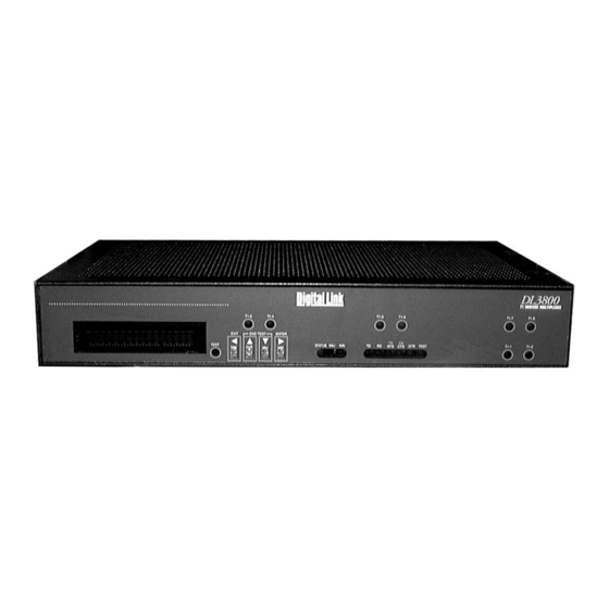
Quick Install Guide URPOSE This chapter is designed to be a quick reference for the setup and conÞguration of the DL3800 DS1 Inverse Multiplexer (see Figure 1-1). Please note that not all conÞguration items will be discussed as this chapter serves to get the end user up and running only. -
Page 24: Setup
. For V.35/RS449 V.35/RS449 HSSI conÞguration set the clock to clock. Set the DTE SCTE Normal TD/RD loss condition for . Select , then select to go back to the NONE Confirm EXIT CONFIGURATION MENU. DL3800 DS1 Inverse Multiplexer User Guide—February 1999... -
Page 25: Network Configuration
Network Configuration Set up a port for each T1 line you plan to use. should be set to Alarm should be set for . Your REPORT ACTIVE/RESTORE MODE Use w/auto restore frame/line code normally will be ESF/B8ZS. Primary clock Xmt = Network (assuming carrier or remote unit providing timing) Primary clock RCV should be set to AUTO. - Page 26 DL3800 DS1 Inverse Multiplexer User Guide—February 1999...
-
Page 27: Chapter 2, Introduction
Introduction YSTEM VERVIEW The DL3800 DS1 Inverse Multiplexer bridges the gap between T1 and T3 data services by providing T1 multiplexing of multimegabit (up to 12.224 Mbps) DTE data onto two to eight T1 circuits. The DL3800 Inverse Multiplexer is an economical solution to bandwidth intensive applications as it provides multimegabit data transport without the need for T3 circuits. -
Page 28: Dl3800 Functional Description
T1 ports. The general operation of the DL3800 is explained in the following paragraphs which describe the signal ßow and overhead functions. DL3800 DS1 Inverse Multiplexer User Guide—February 1999... -
Page 29: Signal Flow
T1 framer. The output of the T1 framer is fed into the IMUX framer. Data coming into the DL3800 DS1 Inverse Multiplexer is stored in N independent buffers, where N is the number of conÞgured input channels. -
Page 30: T1 Port Mismatch Detection
This feature is only enabled when the T1 network conÞguration speciÞes FDL mode as ATT or ON. Port number communication is done using a Digital Link proprietary message in the 54016 FDL. Figure 2-2 is a Functional Diagram of the DL3800 showing a unit supporting four T1 lines. -
Page 31: Overhead Functions
Overhead Functions The overhead functions consist of a controller, front panel, two RS232 communication interfaces (terminal and network management), and a power supply. The controller function is performed by a microprocessor on the main board. The controller collects T1 statistics. It also processes T1 alarms and performance monitoring information, as well as supporting unit conÞguration, test and maintenance activities. -
Page 32: Dl3800 System Features
¥ Local and remote access via front panel, terminal, or telnet ¥ Complete maintenance and diagnostic support via exhaustive alarm, statistic and test capabilities ¥ Downloadable code provides for on-line upgrade to the DL3800 software for both major and minor feature enhancements DL3800 DS1 Inverse Multiplexer User Guide—February 1999... -
Page 33: Application
PPLICATION The DL3800 DS1 Inverse Multiplexer is designed to transport slightly more than 12 Mbps of data over eight grouped T1 lines. The user can transport large amounts of data without having to move up to more expensive T3 transport, retaining the investment made in T1 technology and equipment. - Page 34 DL3800 DS1 Inverse Multiplexer User Guide—February 1999...
-
Page 35: Chapter 3, Installation
NOTE: Before beginning the installation process, inspect the DL3800 for damage which may have occurred during shipment. If damage has occurred, notify Digital Link and your package carrier immediately. 1. Unpack and inspect the DL3800 for damage that might have occurred during shipment. -
Page 36: Mounting The Dl3800
Digital Link. Desk Operation And Stacking Four stick-on rubber feet are supplied with each DL3800 DS1 Inverse Multiplexer. Remove the covering from each rubber foot, and stick them onto the bottom of the DL3800. The DL3800 units may now be stacked as required on a ßat surface in a well-ventilated and secure area. -
Page 37: Power Cables And Connections
DL3800, and plug into the nearest AC outlet. DC Power Connection The Digital Link DL3800 DS1 Inverse Multiplexer can also be powered by a -48 to -72 VDC power source. The DC power connection on the DL3800 is located on the back panel. There are eight screw terminals located on the rear panel. -
Page 38: T1 Network Connection
Digital Link. Using the appropriate cable and connectors, connect the DL3800 HSSI connector to the HSSI DTE. If using a V.35 interface, use a shielded cable supplied by Digital Link to connect the DL3800 to the DTE. One DB-25 socket connector is provided on the back of the DL3800 to connect the DL3800 to the V.35/RS-449... -
Page 39: Ascii Terminal And Snmp Connection
DL3800. Then, connect the modem to the phone line and the ASCII terminal or SNMP workstation. DE-9 to DB-25 adapters and null-modem adapters are available from Digital Link. Specify a plug or socket terminal connection when ordering. For direct connection, the terminal, workstation, or modem may be placed up to 50 feet away from the comm port when operating at 9600 baud. -
Page 40: Daisy Chaining
DL3800s. The cable can be ordered to daisy-chain four units (part # 154-00051-01), eight units (part # 154- 00052-01), or twelve units (part # 154-00053-01). To place an order contact the Digital Link Sales department at (408) 745-6200. If using a cable other than the above, see ÒTerminal ConnectionÓ... -
Page 41: Chapter 4, Terminal Interface
Terminal Interface Each DL3800 is equipped with an integrated RS-232 ASCII user interface that can be accessed through the COMM PORT (DE-9 connector) located on the rear panel of the DL3800. Through this interface, the user can perform various functions described in this section. When operating in multidrop mode (multiple DL3800s may be daisy- chained together for centralized network management), the user must log in to establish communication with a single unit on the network. -
Page 42: Terminal Operation Overview
Status Bar. The Þrst line of the Status Bar displays the product type, the software release number, node number, node name, date & time, and current alarm status of the unit. The second line displays the selected device address and name. DL3800 DS1 Inverse Multiplexer User Guide—February 1999... - Page 43 Figure 4-1 INVERSE MULTIPLEXER MAIN MENU The product type is a DL3800 Digital Inverse Multiplexer. The software revision is , where xx equals the latest software revision. 3.XX This number is useful to determine the features that are supported with this release.
-
Page 44: Select Local/Remote
To move to the Main Menu of the other DL3800, highlight SELECT and press Enter. The Device Address and Name in the LOCAL/REMOTE header should change to the new unit as shown in Figure 4-2. DL3800 DS1 Inverse Multiplexer User Guide—February 1999... -
Page 45: Alarms And Status
Figure 4-2 Main Menu with remote unit selected LARMS AND TATUS The ALARMS AND STATUS MENU is a view only screen that allows the user to review the current ALARMS AND STATUS items being reported by the DL3800. To access this screen, move the highlight bar in the INVERSE MULTIPLEXER MAIN MENU to and press Enter. -
Page 46: Table 4-2 Alarms And Status
Xmt Failed Sync-Net 1 LT On User Line Lpbk Sync-Net 2 TA On User Payload Lpbk Sync-Net 3 LA On HW Line Lpbk Sync-Net 4 LB On HW Payload Lpbk Sync-Net 5 DSR On DL3800 DS1 Inverse Multiplexer User Guide—February 1999... - Page 47 Table 4-2 Alarms and Status (Continued) Network Common Equipment * Active Sync-Net 6 CTS On Not Active Sync-Net 7 RLSD On Excessive Delay Sync-Net 8 TM On Set Code Detected No Net Sync CA On Reset Code Detected LC On CRC Threshold SES Threshold UAS Threshold...
-
Page 48: Statistics
This menu item allows the user to access the performance STATISTICS SUB-MENU of any T1 port. Highlight in the INVERSE MUX STATISTICS MAIN MENU, and press the Enter key. The STATISTICS MENU will appear on the screen. Figure 4-4 STATISTICS MENU DL3800 DS1 Inverse Multiplexer User Guide—February 1999... - Page 49 To view the performance statistics of any one T1 port, highlight that port and press Enter. The NET STATISTICS for that port (Figure 4-5) will appear on the screen. The NET STATISTICS display presents the current and network performance statistics for the Current 15-minute interval, for the past 24 hours (CUMULATIVE 1) and the 24 hours preceding that interval (CUMULATIVE 2), in 15- minute increments.
-
Page 50: Table 4-3 Statistics Menu Error Types
SEF/AIS Seconds. In ESF only, this parameter is the count of one-second intervals containing one or more SEF defects or one or more AIS (Alarm Indication Signal) defects. AISS This parameter is a count of one-second intervals containing one or more AIS defects. 4-10 DL3800 DS1 Inverse Multiplexer User Guide—February 1999... -
Page 51: Event History
Table 4-3 STATISTICS MENU Error Types (Continued) Parameter Definition This is a count of one-second intervals in which the DS1 path has been unavailable. The DS1 path is determined to be unavailable from the onset of 10 contiguous SESs, or the onset of the condition leading to a failure. -
Page 52: Configuration
Menus to conÞgure various parameters of the unit, DTE and network. Highlight in the INVERSE MULTIPLEXER MAIN MENU Configuration and press the Enter key to access the CONFIGURATION MENU, shown Figure 4-8. 4-12 DL3800 DS1 Inverse Multiplexer User Guide—February 1999... -
Page 53: Unit Configuration
Figure 4-8 CONFIGURATION MENU To access any of the CONFIGURATION SUB-MENUS, highlight the desired item and press the Enter key. The following are samples and descriptions of the Sub-Menus that can be accessed from the CONFIGURATION MENU. Unit Configuration Highlighting and pressing the Enter key accesses the UNIT Unit CONFIGURATION MENU shown in... - Page 54 To change the Front Panel feature, highlight Front Panel, and use the Space Bar to toggle between Off and On. 4-14 DL3800 DS1 Inverse Multiplexer User Guide—February 1999...
- Page 55 Table 4-5 Node Configuration Options (Continued) Option Action Unit Number Move the Highlight bar to Unit Number, and enter a number between 0 and 9999. Note: Each unit must be set to a different number to allow remote communication, and daisy chaining of multiple units. For example, if the remote unit is set to the same number as the local unit, you will not be able to access the remote unit.
-
Page 56: Dte Configuration
DTE Interface. Use the Space Bar to toggle between V.35, RS-449, and HSSI until the desired choice appears. Highlight Confirm, and press the Enter key to confirm the change. (Default - V.35) 4-16 DL3800 DS1 Inverse Multiplexer User Guide—February 1999... - Page 57 Table 4-6 DTE CONFIGURATION MENU Options (Continued) Parameter Description/Action Clock This item allows the user to enable either the SCT or SCTE leads, and to set the transmit (Tx), and receive (Rx) to Normal or Inverted mode. To set the DTE Clock parameters, use the up and down arrow keys to highlight the configurable Clock items, and use the Space Bar to toggle between the selections until the desired choice appears.
-
Page 58: Network Configuration
CSU. The NETWORK CONFIGURATION MENU will be slightly different, depending on which version DL3800 is being used. Figure 4-11 shows the NETWORK CONFIGURATION MENU of the DSX version. Table 4-7 describes the various parameters included. 4-18 DL3800 DS1 Inverse Multiplexer User Guide—February 1999... -
Page 59: Table 4-7 Network Configuration Menu Options
Figure 4-11 Network Configuration Screen (DSX-1 Mode) Table 4-7 NETWORK CONFIGURATION MENU Options Parameter Description/Action Alarm This item allows the user to enable (Report) or disable (Mask) the DL3800 from reporting alarms or sending SNMP traps from any of the individual T1 network ports. - Page 60 To change the present LBO, use the up and down arrow keys to highlight the LBO item in the appropriate line for the desired port, and use the Space Bar to toggle between the following selections until the 0dB, -7.5dB, -15dB, and -22.5dB. (Default -)dB) 4-20 DL3800 DS1 Inverse Multiplexer User Guide—February 1999...
- Page 61 Table 4-7 NETWORK CONFIGURATION MENU Options (Continued) Parameter Description/Action JIT (CSU Only) This allows the user to set Jitter Attenuation to either the Transmit (TX) or Receive (RX) side of the line. To change the present Jitter Attenuation side, use the up and down arrow keys to highlight the JIT item in the appropriate line for the desired port, and use the Space Bar to toggle between TX and RX until the desired choice appears.
- Page 62 Space Bar to toggle between Enabled and Disabled until the desired choice appears. Highlight Confirm, and press the Enter key to confirm the change. (Default - Disabled) 4-22 DL3800 DS1 Inverse Multiplexer User Guide—February 1999...
-
Page 63: Network Thresholds
Table 4-7 NETWORK CONFIGURATION MENU Options (Continued) Parameter Description/Action Second Error Restoral This item selects the time that a failed T1 line must run without errors in Interval order to be restored automatically. If a network alarm is exceeded for a second time within the selected window (15 minutes or 24 hours), the line will not be restored. -
Page 64: Save Configuration
Figure 4-13 is an example of the SYSTEM UTILITIES MENU that will appear. To access any of the Sub-Menus or perform certain functions, highlight that line item, and press the Enter key. 4-24 DL3800 DS1 Inverse Multiplexer User Guide—February 1999... -
Page 65: Software Download
¥ A PC with a disk drive capable of reading an MS DOS binary Þle is required. Digital Link provides a 3.5 inch ßoppy formatted for 1.4 Mb for downloading software. ¥ A terminal emulation program such as Procomm, Mirror, or Xtalk with VT100 or ANSI emulation that supports one or all of the following: ¥... - Page 66 6. Once the Þle has downloaded, the DL3800 will take up to 30 seconds to reboot if the IMMEDIATE SOFTWARE ACTIVATION feature is enabled. If any communications errors were encountered, it may be necessary to perform this operation again. 4-26 DL3800 DS1 Inverse Multiplexer User Guide—February 1999...
-
Page 67: Software Download Options
Software Download Options Immediate Software Activation (Enable/Disable) The IMMEDIATE SOFTWARE ACTIVATION mode is controlled from the SYSTEMS UTILITIES/SOFTEWARE DOWNLOAD MENU. When the IMMEDIATE SOFTWARE ACTIVATION feature is enabled, the software download (using MSR, Xmodem, Kermit, TFTP) is immediately activated (that is, copied from RAM to FLASH and rebooted). For consistency with the previous software version, IMMEDIATE=enabled is the default setting. -
Page 68: Ram Software Options
An extended loss of power causes the non-activated software download to be lost. Modifying this setting in the Remote Unit is performed by Þrst logging into the remote unit from the Main Menu, then navigating to this menu. 4-28 DL3800 DS1 Inverse Multiplexer User Guide—February 1999... -
Page 69: Delete Entire Unit Configuration (Revert To Factory Config)
TFTP Software Download If immediate software activation is enabled on the target unit, the software is downloaded to the target unit, and is activated by copying the code from RAM to FLASH and then rebooting. A TFTP Software Download server is built into the DL3800. This feature allows the user to do an TFTP transfer (using the SLIP/NMS port) to the unit RAM. -
Page 70: Login Configuration
ACCESS PRIVILEGE LEVEL for up to eight users. When the unit is shipped, the factory defaults for username and password are null. Pressing the Enter key bypasses both of these parameters until the Þrst name and password are entered. 4-30 DL3800 DS1 Inverse Multiplexer User Guide—February 1999... -
Page 71: Figure 4-15 Login Configuration Menu
To access the LOGIN CONFIGURATION MENU, move the highlight bar to in the NODE MAIN MENU and press the Enter LOGIN CONFIGURATION key. Figure 4-15 is an example of the LOGIN CONFIGURATION MENU. Figure 4-15 LOGIN CONFIGURATION MENU NOTE: Name and Password are case-sensitive Only those users who are granted "Full Access"... - Page 72 NOTE: If the user tries to access a screen or perform a function beyond their access level allowed, the following message will appear on the screen: “Access denied - your account does not have this PRIVILEGE”. 4-32 DL3800 DS1 Inverse Multiplexer User Guide—February 1999...
-
Page 73: Snmp Configuration
SNMP Configuration Through the SNMP CONFIGURATION MENU, the user conÞgures the Network Manager (NMS) port on the rear panel of the DL3800, setting various addresses and conÞgurable items required for operation with an SNMP Network Manager. The DL3800 utilizes SLIP protocol over the RS232 port to communicate with the SNMP management station. - Page 74 SNMP network that is able to receive event messages from the node. To set or change the Trap Community String, move the highlight bar to Trap Community String, and enter an alphanumerical identifier. Press Enter when finished. 4-34 DL3800 DS1 Inverse Multiplexer User Guide—February 1999...
- Page 75 Table 4-9 SNMP Configuration Options (Continued) Option Description/Action SNMP Baud Rate This feature selects the SNMP port’s baud rate. To set or change the SNMP port baud rate, move the highlight bar to SNMP Baud Rate, and press the Space Bar to toggle between the options until the desired speed appears.
-
Page 76: In-Band Snmp To Remote
LOOPBACK for the DTE, PAYLOAD LOOPBACK, LINE LOOPBACK, and LOCAL LOOPBACK. For troubleshooting suggestions see ÒTroubleshooting the DL3800Ó on page 6-3. To access the TESTS MENU, move the highlight bar to in the DL3800 TESTS Main Menu, and press Enter. 4-36 DL3800 DS1 Inverse Multiplexer User Guide—February 1999... -
Page 77: Dte/Network Loopback
Figure 4-17 is an example of the TESTS MENU. The individual loopbacks and operation of the menu are described below in the text following the menu. Figure 4-17 TESTS MENU To initiate a test, use the CURSOR keys to move the highlight bar to or a on a selected port. -
Page 78: Payload Loopback
DTE at the network interface. WARNING: The Loopback tests will interrupt traffic to the DL3800. Line DTE/NETwork Payload Local Loopback Loopback Loopback Loopback Framer Interface Transceiver Network DL3800 Figure 4-18 Loopbacks Within the DL3800 4-38 DL3800 DS1 Inverse Multiplexer User Guide—February 1999... -
Page 79: Manual Network Restoration
Manual Network Restoration The DL3800Õs T1 ports are normally set to auto restore. However, you may choose to individually restore T1 networks after they fail, through the MANUAL NETWORK RESTORATION MENU. NOTE: Manual restore will only work under the following conditions: 1. -
Page 80: Logout
This allows the user to manually logoff the unit, instead of waiting for the provisioned automatic logoff time for the unit to logoff automatically. Highlighting and pressing Enter logs the user off the system. LOGOUT 4-40 DL3800 DS1 Inverse Multiplexer User Guide—February 1999... -
Page 81: Chapter 5, Front Panel Interface
Front Panel Interface ENERAL The front panel features a 16 character vacuum ßuorescent display and four buttons that help the user to move through the various menus to conÞgure the unit, perform tests, and obtain vital performance data. The front panel also features six LEDs for the DTE port, one for each of the T1 networks, three for the DL3800 status and one for Network Test. -
Page 82: Button Overview
If no tests are active, pressing the End Test combination has no effect. Enter Button The ENTER button is used to select a sub-menu loop or conÞguration option. This button doubles as the right arrow button in a few situations. DL3800 DS1 Inverse Multiplexer User Guide—February 1999... -
Page 83: Front Panel Leds
Front Panel LEDs Table 5-1 Front Panel LEDs Indication Description Test Test In Progress LED No tests are in progress. Solid Red A test condition exists. Data Port LEDs Data DTE Activity LED. Represents pulses from DTE. Green Pulses are being detected. No pulses are being detected. -
Page 84: Access Levels And Protected Mode
This procedure takes the unit out of the Protected Mode (and clears any password that may have been programmed into the unit). To allow the user to perform this procedure when the unit is in protected mode, the DL3800 DS1 Inverse Multiplexer User Guide—February 1999... -
Page 85: Power Up And Reset
Protected Mode is ignored in the Þrst sixty seconds after powering the unit up. When in Protected Mode, the Test Menu does not appear in the Main Menu as a choice. OWER ESET During power up initialization, the unit performs self test and displays a self-test message. -
Page 86: Select Remote/Select Local
The Test Menu is used for DTE and Network loopbacks. The DL3800 does not allow performing tests on the remote unit through the front panel user interface. This feature is only available with the terminal interface. DL3800 DS1 Inverse Multiplexer User Guide—February 1999... -
Page 87: Display Menu
The ConÞguration Menu is used to view and change the unit's conÞguration parameters, date and time, network interface parameters, and DTE interface parameters. Both the Monitor and ConÞguration Menus are also able to access the remote unit. Remote monitoring and conÞguration are only available when there is an ADL (Application Data Link) channel to the remote unit. -
Page 88: Node (Common Equipment) Status
Node (Common Equipment) Status This display shows the status of the unit. NODE STATUS is accessed from the DISPLAY Menu by pressing ENTER when appears in the NODE STATUS display. DL3800 DS1 Inverse Multiplexer User Guide—February 1999... -
Page 89: Dte Status
If one of more errors are detected, one or more of the following messages will appear. Use the up and down arrow buttons to view the following messages, see Table 4-2 on page 4-6 of this Users Manual for a list of those Common Equipment Alarm and Status items that could appear in this menu. -
Page 90: Table 5-3 Net Statistics Items
In ESF format, Severely Errored Seconds are defined as a count of one-second intervals with 320 or more CRC-6 errors, or an SEF defect. In SF, it is the count of one-second intervals with eight or more FE events or an SEF defect. 5-10 DL3800 DS1 Inverse Multiplexer User Guide—February 1999... -
Page 91: Test Menu
Table 5-3 NET Statistics Items (Continued) Parameter Definition In ESF only, this parameter is the count of one-second intervals containing one or more SEF defects or one or more AIS (Alarm Indication Signal) defects. AISS This parameter is a count of one-second intervals containing one or more AIS defects. This is a count of one-second intervals in which the DS1 path has been unavailable. - Page 92 NET 3 TESTS LINE LOOPBACK EXIT Use Up/Down Arrows to select PAYLD, LINE or LOCAL Loopback. EXIT ENTER Strike ENTER to actiuvate. NET 4 TESTS PAYLD LOOP EXIT Return to Menu item: TESTS 5-12 DL3800 DS1 Inverse Multiplexer User Guide—February 1999...
-
Page 93: Dte Tests
NOTE: A menu item will appear only for those T1 network interfaces. installed. DTE T ESTS Only one loopback can be initiated through the DTE TESTS Menu, a bi- directional DTE/NET Loopback. To access the DTE TESTS Menu from the TEST Menu, press ENTER when DTE TESTS appears in the display. -
Page 94: Network Tests (1 Through 8)
PAYLD LOOPBACK in the display. Payload Loopback When the loopback is terminated, the "plus sign" disappears. To end the loopback, press ENTER again while still in the PAYLD LOOPBACK MENU. 5-14 DL3800 DS1 Inverse Multiplexer User Guide—February 1999... -
Page 95: Line Loopback
Line Loopback The network loopback is used to verify the operation of the T1 network connection (T1 through T8). The network loopback loops the data received from the T1 network back towards the network. The data is regenerated prior to being looped back, however, no additional processing of the data is performed by the DL3800. - Page 96 C ON FIGUR ATION Table 5-4 CONFIGURATION MENU Items Menu Definition NODE CONFIG MENU Used to set the unit’s ID, date, time, and communications port. It also shows the user the hardware and software versions 5-16 DL3800 DS1 Inverse Multiplexer User Guide—February 1999...
-
Page 97: Node Configuration
Table 5-4 CONFIGURATION MENU Items (Continued) Menu Definition Backup Database Used to manually back-up the database to EEPROM DTE CONFIG MENU Used to set the line mode for the DTE DATA port. It is also used to define whether the DTE signal is defined missing when the DTR and the RTS line is not asserted. - Page 98 Date and Time menu DATE & TIME EXIT ENTER ENTER Node Comm Port Sub menus NODE COMM PORT EXIT EXIT ENTER Node HW Rev NODE HW REV EXIT ENTER SW Rev SW REV EXIT 5-18 DL3800 DS1 Inverse Multiplexer User Guide—February 1999...
- Page 99 The NODE CONFIGURATION MENU is used to conÞgure various parameters of the DL3800, including: Table 5-5 NODE CONFIGURATION MENU Items Parameter Definition Unit ID The Unit ID is an alphanumeric designation up to 16 characters in length. The unit is shipped without a Unit ID. To access Unit ID from the NODE CONFIGURATION MENU press...
- Page 100 Multidrop Mode. If it is connected to only one unit, this feature can be disabled. When it is disabled, the system comes up directly, without the user having to log in. The choices are Multidrop Mode and Direct Terminal. 5-20 DL3800 DS1 Inverse Multiplexer User Guide—February 1999...
- Page 101 COMM PORT CONFIG Arrow keys change EXIT ENTER ENTER baud rate BAUD RATE 9600 BAUD RATE 9600 EXIT EXIT Arrow keys change EXIT ENTER ENTER parity PARITY EVEN PARITY EVEN EXIT EXIT Arrow keys change EXIT ENTER ENTER length of data bits DATA BITS 8 DATA BITS 8 EXIT...
-
Page 102: Dte Configuration Menu
Pressing the EXIT button aborts the operation without making the change. Each of the ConÞgurable items are described, along with the various options, in detail in ÒNetwork ConÞgurationÓ on page 4-18 of this User Manual. 5-22 DL3800 DS1 Inverse Multiplexer User Guide—February 1999... -
Page 103: Net N Config
NETWORK CONFIGURATION Menu EXIT ENTER Up and Down arrow buttons change INVERSE MUX INVERSE MUX operating mode between Inverse EXIT Mux and Single T1 DSU. EXIT ENTER Up and Down arrow buttons change PRI TX CLK INT PRI TX CLK INT Primary TX Clock source between EXIT Internal, External and Network. -
Page 104: Network Thresholds
Consecutive seconds (1-100) containing errors, for the number of seconds containing errors in a 15-minute interval (1-900), and for the number of 15-minute intervals containing errors in a 24-hour period (1-96). 5-24 DL3800 DS1 Inverse Multiplexer User Guide—February 1999... -
Page 105: Table 5-6 Net Threshold Options And Values
The user can set the threshold value for Minor (MI) and Major (MJ) alarms, where exceeding the Minor alarm threshold will generate an alarm report and the exceeding a Major alarm threshold will actually cause a T1 line to be automatically taken out of service. Pressing the ENTER button when NET THRESHOLDS appears in the display screen will start the menu and allow the user to scroll, using the down or up arrow buttons, through the following options:... - Page 106 ON or OFF. To change an alarm threshold value, use the Up and Down arrow buttons to get to that particular alarm and press ENTER . Use the Up or Down buttons to raise or lower the value. 5-26 DL3800 DS1 Inverse Multiplexer User Guide—February 1999...
-
Page 107: Chapter 6, Diagnostics
ESTS You should test the DL3800 before you use it. If it, or an associated module, does not operate properly during or after testing, call Digital Link Technical Support at: (408)Ê745-4200. This chapter contains procedures for testing the DL3800 followed by suggestions for troubleshooting problems. -
Page 108: Dte/Network Loopback Test
Use the LOCAL Loopback test to verify the operation of the DL3800 data port and its connections. To receive valid test data at the DTE device, run LOCAL Loopback on all active T1 ports. DL3800 DS1 Inverse Multiplexer User Guide—February 1999... -
Page 109: Payload Loopback And Line Loopback Tests
Payload Loopback and Line Loopback Tests Use the PAYLOAD Loopback and LINE Loopback tests to verify the proper operation of the DL3800 and selected T1 networks. Both tests loop the payload data received from the T1 network back to the network. -
Page 110: Table 6-1 Troubleshooting (1 Of 5)
If a test is running, end it by selecting the test and set it to Off in the DTE and NETWORK TESTS MENU Make sure the DTE device or the T1 carrier is not sending loop up and loop down codes. DL3800 DS1 Inverse Multiplexer User Guide—February 1999... - Page 111 Table 6-1 Troubleshooting (2 of 5) Problem Solution The NETWORK T1 port Make sure the T1 cable from your service provider is connected to the LED’s on the DL3800 never DL3800. illuminate. Remove the T1 cable from the affected T1 port, and hardloop the interface by connecting pins 1-3 and 9-11 of the DB-15 port.
- Page 112 Alarm thresholds may have been exceeded for the 15 minute or 24 hour Minor Alarm LEDs on the periods. If other thresholds have not been exceeded, the DL3800 DL3800 do not clear. automatically clears these alarms after the period has passed. DL3800 DS1 Inverse Multiplexer User Guide—February 1999...
- Page 113 Table 6-1 Troubleshooting (4 of 5) Problem Solution The connected DTE device Run a DTE/NET Loopback to verify the physical connection between the shows intermittent errors. local DTE device and the DL3800. If errors are reported during this loopback, check the DTE cable. Make sure the DTE device supports the DTE port clocking option.
- Page 114 Make sure the Comm Port parameters match the terminal’s, and the DL3800 has a unique ID. If the DL3800 is in a daisy-chain, you can display a roll call of all unit numbers by pressing Ctrl-x five times. DL3800 DS1 Inverse Multiplexer User Guide—February 1999...
-
Page 115: Appendix A, Speciþcations
SpeciÞcations T1 N ETWORK NTERFACE Parameter Setting Interface Type DSX-1 Standard T1 CSU Optional Number of Ports 2, 4, 6 or 8 Framing Formats D4 or ESF ESF FDL Protocols AT&T 54016 ANSI T1.403 Line Code AMI or B8ZS Transmit Line Rate 1.544 Mbps ±... -
Page 116: Dte Interface
COMM P Item Interface Interface Devices Terminal or Modem Protocol User-friendly menu driven Electrical RS-232 socket NMS P (SNMP) Item Interface Interface Devices SNMP Manager Protocol SNMP (UDP/IP) over SLIP Electrical RS-232 socket DL3800 DS1 Inverse Multiplexer User Guide—February 1999... -
Page 117: Front Panel
RONT ANEL Item Interface Display 16 Character Alphanumeric Key Pad Four Keys DTE Status LEDs TD, RD, RTS, CTS, DTR, network data/test, T1-1 through T1-8, status, MAJ alarm, MIN alarm IAGNOSTICS Item Interface Loopbacks DTE/Network, Payload, Line, Local Self Test Checks Unit Circuitry and Memory on power up Alarms Relay, dry contact... -
Page 118: Environmental
ONNECTORS Item Dimensions Mounting 19-inch or 23-inch rack mounting or Standalone Dimensions 17.2 in W x 2.8 in H x 11in D (43.7 cm W x 7.1 cm H x 27.9 cm D) DL3800 DS1 Inverse Multiplexer User Guide—February 1999... -
Page 119: Appendix B, Pinouts
Pinouts ERMINAL ONNECTION Table B-1 COMM and NMS Port Pin Assignments SIGNAL 2 SD Send Data to Terminal 3 RD Receive Data from Terminal 8 CTS Clear to Send to Terminal (Connect between units, but not to the Terminal) 5 SG Signal Ground (Bidirectional) DTE C ONNECTORS... - Page 120 14-18 39-43 — Signal Ground 5 ancillary from DCE 5 ancillary from DCE To DTE 20-24 33-49 — Signal Ground Table B-3 DB-25 to V.35 DTE Connector Pin Assignments TWISTED PAIR V.35 DB-25 DL3800 DS1 Inverse Multiplexer User Guide—February 1999...
-
Page 121: Table B-3 Db-25 To V.35 Dte Connector Pin Assignments
Table B-3 DB-25 to V.35 DTE Connector Pin Assignments TWISTED PAIR V.35 DB-25 DRAIN Table B-4 DB-25 to RS-449 DTE Connector Pin Assignments TWISTED PAIR RS449 DB25 Pinouts... -
Page 122: T1 Network Pin Assignments
Not Connected DB-25 DE-9 A DAPTER INOUTS An adapter is available from Digital Link that will allow the Digital Link DE-9 ribbon cable to be compatible with a DB-25 connector on the terminal port. Table B-6 DB-25 to DE-9 Pinouts DB25 DL3800 DS1 Inverse Multiplexer User Guide—February 1999... -
Page 123: External Clock Connector Pin Assignments
Table B-6 DB-25 to DE-9 Pinouts DB25 External Clock Connector Pin Assignments A DE-9 connector is provided on the DL3800 rear panel for connection to an External Clock. Pin Assignments for the External Clock connector are as follows: Table B-7 External Clock Pinouts SIGNAL Signal A... -
Page 124: Dte Clock Rates
DTE Clock Rates Table B-8 DTE Clock Rates NETWORKS DTE CLOCK RATE, MBPS B8ZS 1.528 3.056 4.584 6.112 7.640 9.168 10.696 12.224 1.336 2.672 4.008 5.344 6.680 8.016 9.352 10.688 DL3800 DS1 Inverse Multiplexer User Guide—February 1999... -
Page 125: Appendix C, Factory Default Settings
Factory Default Settings Table C-1 Unit Settings Unit Setting ALARM ENABLE Disabled AUTOMATIC BACKUP 5 minutes after each database change FRONT PANEL UNIT NUMBER TERMINAL BAUD RATE 9600 TERMINAL PARITY & BITS 8 bits, No parity TERMINAL STOP BITS XON/XOFF Enabled MULTIDROP Enabled... -
Page 126: Table C-3 Network Settings
Fallback Disabled MIN) Seconds Major 100 Minor 100 INTERVAL THRESHOLDS (24 HR) Fallback Disabled Seconds Major 10 Minor 10 Table C-5 SNMP Configuration Settings SNMP Configuration Setting ALL ADDRESSES 0.000.000.000 READ COMMUNITY STRING Public DL3800 DS1 Inverse Multiplexer User Guide—February 1999... -
Page 127: Table C-6 Test Settings
Table C-5 SNMP Configuration Settings SNMP Configuration Setting WRITE COMMUNITY STRING Public TRAP COMMUNITY STRING Public SNMP BAUD RATE 9600 BITS & PARITY 8 bits, No parity STOP BITS Table C-6 Test Settings Tests Setting ALL LOOPBACKS & TESTS Factory Default Settings... - Page 128 DL3800 DS1 Inverse Multiplexer User Guide—February 1999...
- Page 129 Glossary ABAM A designation for 22 gauge, 110 ohm, plastic insulated, twisted pair Western Electric cable normally used in central ofÞces. AIS (Alarm Indication Signal) An unframed sequence of All Ones normally sent by a DSU/CSU that cannot maintain the required pulse density in AMI mode or sent by a CSU that has a loss of signal condition on its data port.
- Page 130 Services or interfaces that operate above the T1 data rate, typically at NxT1, T3, SONET, or ATM speeds. BPV (Bi Polar Violation) Occurs when the ones bit is not represented with the opposite signal of the previous ones bit. DL3800 DS1 Inverse Multiplexer User Guide—February 1999...
- Page 131 CCITT International Telegraph and Telephone Consultative Committee. central ofÞce (CO) The phone company switching facility or center; usually a Class 5 end ofÞce, at which subscribers' local loops terminate. channel A physical or logical path allowing the transmission of information; the path connecting a data source and receiver.
- Page 132 In the OSI model, the network processing entity that establishes, maintains and releases data link connections between adjacent elements in the network. DL3800 DS1 Inverse Multiplexer User Guide—February 1999...
- Page 133 DCE (Data Circuit-Terminating Equipment) Equipment that is either a part of the network, an access point to the network, a network node, or equipment at which a network circuit terminates. dial-up Describing the process of, or the equipment or facilities involved in, establishing a temporary connection via the switched telephone network.
- Page 134 ES (Errored Second) Occurs when a second has one or more OOF events or CRC violations or with one or more BPV or OOF events. G-10 DL3800 DS1 Inverse Multiplexer User Guide—February 1999...
- Page 135 ESF (Extended Superframe Format) A new T1 framing standard used in Wide Area Networks (WANs). With this format 24 frames, instead of 12 are grouped together. ESF provides frame synchronization, cyclic redundancy checking and data link bits in overhead. It allows more information to be stored and retrieved easily, facilitating network performance monitoring and maintenance.
- Page 136 This allows a technician (or built-in diagnostic circuit) to compare the returned signal with the transmitted signal and get some sense of what's wrong. G-12 DL3800 DS1 Inverse Multiplexer User Guide—February 1999...
- Page 137 LOS (Loss of Signal) Occurs when an input signal is detected as all zeros for 176 bit times. loss A reduction in signal strength, expressed in decibels. LSC (Loopback Select Code) An indicator describing a DSU loopback characteristic. LSC is a minimum of 35 LSC bytes of S11101F1 with secondary channel.
- Page 138 The physical point of access into a computer, network or other electronic device. protocol A formal set of rules governing the format, timing, sequencing and error control of exchanged messages on a data network. G-14 DL3800 DS1 Inverse Multiplexer User Guide—February 1999...
- Page 139 RD (Receive Data) A data port signal. receiver The receiver synchronizes the framing pattern, separates the frame bits from the payload data and monitors for frame errors in 64 kbps mode. It achieves frame synchronization within 5 milliseconds. repeater Equipment that receives a pulse train, ampliÞes it, retimes it, and then reconstructs the signal for retransmission.
- Page 140 SMDS (Switched Multimegabit Data Service) A fast-packet technology based on the connection-less data networking capability described in the IEEE 802.6 speciÞcation. The data format for SMDS is Òcell oriented.Ó SMDS does not support voice. G-16 DL3800 DS1 Inverse Multiplexer User Guide—February 1999...
- Page 141 SNMP (Simple Network Management Protocol) A widely-used network monitoring and control protocol. Data is passed from SNMP agents (hardware and/or software processes reporting activity in each network device, hub, router, bridge, etc.) to the workstation console used to oversee the network. The agents return information contained in a MIB (Management Information Base), which is a structure that deÞnes what is obtainable from the device and what can be controlled.
- Page 142 Operating modes include local and remote digital loopback and local and remote analog loopback. V.54 A CCITT standard for loop test devices in modems. It deÞnes local and remote loopbacks. G-18 DL3800 DS1 Inverse Multiplexer User Guide—February 1999...
Need help?
Do you have a question about the DL3800 DS1 and is the answer not in the manual?
Questions and answers