Table of Contents
Advertisement
Quick Links
Digital room unit DD1 can be
used with following controller
types:
COMPACT CMP12+
COMPACT CMP12+/R
TERAMATIK D1
TERAMATIK D2
ALL HRD CONTROLLERS.
SELTRON d.o.o.
Ruška cesta 96
SI-2345 Bistrica ob Dravi
Slovenija
tel: +386 (0)2 671 96 00
fax: +386 (0)2 671 96 66
http: //www.seltron.si
Email: info@seltron.si
User manual
Setting manual
Installation manual
J5060098 v3.0
User manual
Setting manual
Installation manual
J5060098 v3.0
DIGITAL ROOM UNIT
DD1
DIGITAL ROOM UNIT
DD1
Advertisement
Table of Contents

Summary of Contents for Seltron DD1
- Page 1 User manual Setting manual Installation manual DIGITAL ROOM UNIT Digital room unit DD1 can be used with following controller types: COMPACT CMP12+ COMPACT CMP12+/R TERAMATIK D1 TERAMATIK D2 ALL HRD CONTROLLERS. SELTRON d.o.o. Ruška cesta 96 SI-2345 Bistrica ob Dravi...
- Page 2 We are thanking you for your confidence by buying a Technical data SELTRON product. Rated operating voltage .....8 V d.c.; max. 20 V d.c. We will further try to deepen and strengthen your confidence Rated supply current ......max. 5 mA d. c.
-
Page 3: Table Of Contents
Error ERR 02 will always occur by the first connec- Passive operation of digital room unit DD1 .........17 tion of DD1 to the controller, because DD1 isn't Data display in passive operation ..........18 synchronised with the controller. Please see the chapter “... - Page 4 Coding switch SETTING MANUAL Synchronising DD1 with the controller ........24 On the DD1 backside is a 4-position coding Display of temperatures and other data ..........25 Factory settings ................27 switch with following switch meanings: Measured temperatures ..............29 Wanted and calculated temperatures ..........31 Controller settings ................32...
-
Page 5: Preface
SMT technology. During construction we have used modern technology, together with Time of automatic menu exit years of experience and user requests. Room unit DD1 is (20 s, 200 s) simply for use, efficient and reliable and is used for remote control of central heating from our living rooms. -
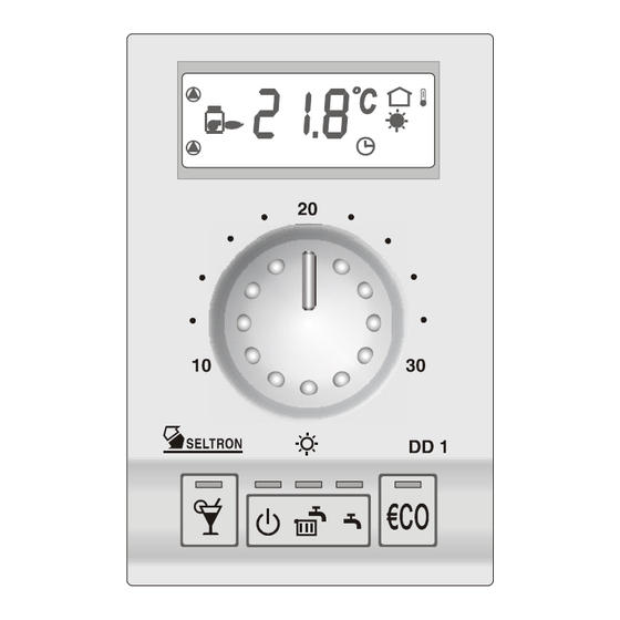
Page 6: User Manual Unit Appearance
Service settings USER MANUAL Unit appearance The picture shows the front view of digital room unit DD1. Rounding of displayed temperatures The display shows different temperatures, operating modes (0,1; 0,2; 0,5 or 1,0 °C) and other data. A key is active, if the LED above it, is on. -
Page 7: Operation Start
Adaptive algorithm Operation start With the connection to the power supply, DD1 starts a self Adaptive algorithm is enabled with coding switch S1=ON. test showing different data on the LCD display in short inter- Room unit DD1 will automatically adapt the controller to the vals. -
Page 8: Lcd Display
LCD Display Local network The display usually shows the measured room temperature, selected operation mode and signalisation of controller operation. Master controller mixing valve mixing valve numerical data room - closing - opening temperatures heating normal UWP- temperature Slave controller no. 1 pump reduced UWP2-... -
Page 9: Setting The Wanted Normal Temperature
Heating curve correction Active operation of digital room unit DD1 Room unit DD1 is guiding the controller if the controllers operating mode selection switch is in position room unit. Heating curve slope correction ( -0,5 ... +0,5) D1, D2 and HRD... -
Page 10: Operating Mode Selection Key
To see the current normal temperature set Controller software version point, press shortly twice the “party” key. Basic programming of DD1 The reduced temperature is set on the controller, operation with the corresponding button. See the controller manual—chapter “Setting the reduced temp.”... -
Page 11: Frost Protection
Room and domestic hot water heating are deactivated. Information Only frost protection is active. 6 °C Room unit type designation (DD1) frost protection Room and d. h. w. heating DD1 software version The controller heats the rooms according to... -
Page 12: Domestic Hot Water Heating
Wanted reduced temperature Domestic hot water heating The controller operates domestic hot water heating according to time program CH2. Selection switch position Room heating is deactivated, frost protection is active. Minimal or maximal temperature for flow temperature limiting d. h. w. heating frost (CH2=ON) protection... -
Page 13: Setting Any Wanted "Party" Temperature
- Heating circuit slope for second heating circuit (DC) - Minimal solid fuel boiler Pressing the key activates the “party” func- temperature tion. DD1 remembers the wanted temperature - Switch-on difference for solar set point. collectors Wanted d. h. w. temperature With this button we set again the wanted normal room temperature. -
Page 14: Setting The Duration Of "Party" Operation
Display symbol - - - means that the temperature Setting the duration of “party” operation isn’t measured and isn’t used by the controller. During active “party” operation press and hold the key for at least 5 seconds. 5 sec Wanted and calculated temperatures With key pressing we can now set the wanted duration... -
Page 15: Key "Economy
KF2 - solid fuel boiler temperature Pressing the key activates the “economy” KTF - solar collectors temperature function. RF2 - DD1 separated room sensor With this button we can now again set the temperature wanted normal room temperature. This setting is used after “economy” operation BDF - estrih temperature ends. -
Page 16: Setting The Duration Of "Economy" Operation
We can change the parameter values for following groups: Setting the duration of “economy” operation “PRO”, “ADT”, “TEL” and “SE1” During active “economy” operation press and We go to the selected parameter, press and hold the key for at least 5 seconds. hold the “operation mode”... - Page 17 Factory settings are ass follows: Passive operation of room unit DD1 Group PRO - programming: DD1 is in passive operation if the operating mode selection - correction of room temperature display ..0.0 °C switch (on the controller) isn’t in position “remote unit”.
-
Page 18: Data Display In Passive Operation
(CH1=OFF) d. h. w. heating Factory settings (CH2=ON) automatic timer To return DD1 to the factory settings we must perform fol- operation lowing actions: The controllers operating mode selecting switch a) Press and hold key “party” and put DD1 is in position “normal temperature operation”. - Page 19 (CH2=ON) protection Controller data The controllers operating mode selecting switch Programming of basic operation of is in position “manual operation” room unit DD1 all pumps and the boiler are manual active operation SETTING MANUAL USER MANUAL...
-
Page 20: Operating Mode Selection Key
Data and settings are divided into 10 groups. The special Selecting the installation place group 11 is used for service settings. The right installation place is very important. DD1 measures and uses the room temperature and so we must choose the To get into group selection we right place to measure the actual room temperature. -
Page 21: Installing The Dd1 Room Unit
The picture shows how to take Synchronising DD1 with the controller DD1 off from the socket. We use For correct operation we must synchronise DD1 with the con- a screwdriver to push up DD1 nected heating controller. Synchronisation is done after con- (trough the opening on the necting all needed sensors to the controller. -
Page 22: Telewarm G1-D
Telewarm G1-D is a remote telephone switch, which enables us to activate normal temperature operation via a telephone We use a two wire cable to connect DD1 to a heating network. Telewarm G1-D can be connected to the controller controller (HRD, D1, D2 or CMP12+). See the wiring or room unit DD1.
Need help?
Do you have a question about the DD1 and is the answer not in the manual?
Questions and answers