Table of Contents
Advertisement
Quick Links
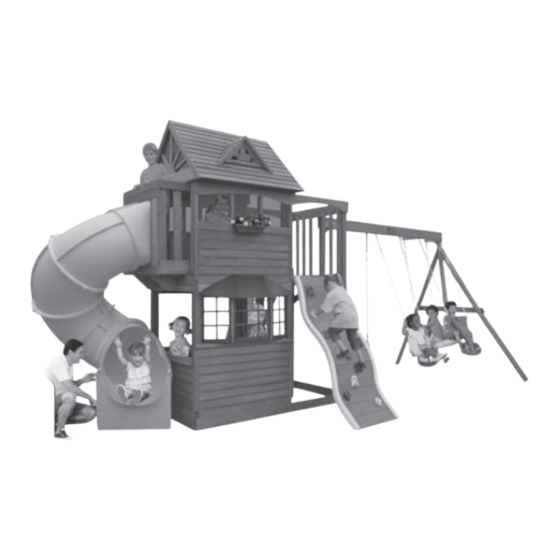
DELUXE LOWER CLUBHOUSE – F24700
for use with SUMMERVILLE PLAY SYSTEM – F23105
INSTALLATION AND OPERATING INSTRUCTIONS
18' 8" (5.7 m)
8 - 10 Hrs
Two person
assembly
3404700SV
WARNING
often and give them to any future owner of this play system. Manufacturer contact information provided below.
OBSTACLE FREE SAFETY ZONE - 32'7" x 28' (9.9 x 8.5 m) area requires Protective Surfacing. See page 3.
MAXIMUM VERTICAL FALL HEIGHT - 6'11" (2.1 m)
CAPACITY - 12 Users Maximum, Ages 3 to 10; Weight Limit 110 lbs. (49.9 kg) per child.
RESIDENTIAL HOME USE ONLY. Not intended for public areas such as schools, churches, nurseries,
day cares or parks
Solowave Design
375 Sligo Rd. West, PO Box 10
Mount Forest, ON Canada N0G 2L1
General Inquiries:
8:00am - 4:30pm EST
Toll Free: 1-877-966-3738
support@solowavedesign.com
To reduce the risk of serious injury or death, you must read and
follow these instructions. Keep and refer to these instructions
Table of Contents
Warnings and Safe Play Instructions . . . . . . . . . . pg. 2
Protective Surfacing Guidelines . . . . . . . . . . . . . . pg. 3
Instructions for Proper Maintenance . . . . . . . . . . pg. 4
About Our Wood – Limited Warranty . . . . . . . . . . pg. 5
Keys to Assembly Success . . . . . . . . . . . . . . . . . . pg. 6
Part ID . . . . . . . . . . . . . . . . . . . . . . . . . . . . . . . . . . pg. 7
Installation of I.D./Warning Plaque . . . . . . . . Final Step
Rev 01/13/2011
Advertisement
Table of Contents

Summary of Contents for Big Backyard DELUXE LOWER CLUBHOUSE F24700
- Page 1 8 - 10 Hrs Two person assembly Solowave Design Table of Contents 375 Sligo Rd. West, PO Box 10 Warnings and Safe Play Instructions ..pg. 2 Mount Forest, ON Canada N0G 2L1 Protective Surfacing Guidelines .
- Page 2 Part Identification (Reduced Part Size) Nominal Size (1) CE Floor Board 1 x 4 x 32-1/2" Actual Size 1½" x 5 ⅜ " 2" x 6" ⅜ " x 3 ⅜ " 2" x 4" 3630304 Box 1A ⅜ " x 2½" 2"...
- Page 3 Part Identification (Reduced Part Size) Nominal Size (2) Cedar Wall 1 x 4 x 28" 3635265 Box 1A Actual Size ⅜ 1½" x 5 " 2" x 6" ⅜ " x 3 ⅜ " 2" x 4" ⅜ 2" x 3" "...
- Page 4 PRODUCT NUMBER: F24700 CARTON I.D. STAMP: __ __ __ __ __ 14459 ___ (Box 1) CARTON I.D. STAMP: __ __ __ __ __ 14459 ___ (Box 2) CARTON I.D. STAMP: __ __ __ __ __ 14459 ___ (Box 3) CARTON I.D. STAMP: __ __ __ __ __ 14459 ___ (Box 4) CARTON I.D.
- Page 5 Step 43: Cafe Canopy Assembly A: Feed all canopy frames through the pockets of the canopy. (fig. 43.1) B: Place the frames together so the U-Frame is inside, then the Z-Frame and lastly the P-Frame on the outside and then attach with 1 (S19) #12 x 1/2” Pan Bolt (with #12 lock nut) per side. (fig. 43.2 & 43.3) Frame Z Frame P Fig.
- Page 6 Step 44: Cafe Wall Assembly A: On the (C13) Post below the Cafe Canopy attach 1 (B4) Lower Trim flush to the edge of the post and tight to the top of (B16) Ground Front Back with 3 (S2) #8 x 1-1/2” Wood Screws. (fig. 44.1) Fig.
- Page 7 Step 44: Cafe Wall Assembly cont. B: Starting tight to the top of (B16) Ground Front Back and tight to the side of (B4) Lower Trim attach 1 (B9) Siding to (C13) Post and (C15) Mid Post with 2 (S0) #8 x 7/8” Truss Screws per siding. (fig. 44.2) C: Attach 5 more (B9) Siding to (C13) Post and (C15) Mid Post with 2 (S0) #8 x 7/8”...
- Page 8 Step 45: Table Top Assembly A: Place (B21) Table Support flush to the notched out extension of (A11) Table Top as shown in fig. 45.2 and attach using 5 (S7) #12 x 2” Pan Screws. Notice the sizing of the notches and their placement. B: Place Table Top Assembly tight to the top of (B9) Siding and the notches in (A11) are tight against (C13) Post and (C15) Mid Post.
- Page 9 Step 45: Table Top Assembly cont. Centre over pilot Fig. 45.4 holes in (B9) Siding C: From the inside of the fort, tight to the bottom of (A11) Table Top and centred over the pilot holes in (B9) Siding, attach both (B1) Cedar Walls to (B21) Table Support with 2 (S2) #8 x 1-1/2”...
- Page 10 Step 46: Stool Seat Assembly A: Using the hardware provided with the Stool Seat Assembly attach 1 Seat to 1 Seat Support and then create a second seat as in fig. 46.1. B: Keeping the Cross Brace tight to the Seat Assemblies, fasten the Cross Brace to each of the Seat Assemblies using the hardware provided.
- Page 11 Step 47: Entrance Wall Assembly A: Attach 1 (D19) Lower Mid Post flush to the bottom and outer edge of each (C15) Mid Post with 4 (S3) #8 x 2-1/2” Wood Screws per board. (fig. 47.2) Fig. 47.1 Fig. 47.2 Part of fort removed for clarity Wood Parts...
- Page 12 Step 47: Entrance Wall Assembly cont. B: Flush to the top and tight to each (B16) Ground Front and Back attach 1 (D20) Ground Divider to each (C15) Mid Post with 4 (S2) #8 x 1-1/2” Wood Screws. (fig. 47.3) C: Attach 1 (D21) Door Top tight to the bottom of (B20) Floor Front Back to each (C15) Mid Post with 4 (S2) #8 x 1-1/2”...
- Page 13 Step 47: Entrance Wall Assembly cont. G: Starting tight to the top of (D20) Ground Divider and tight to the side of (D8) Door Trim attach 1 (D12) Siding to (D19) Lower Mid Post and (D22) Door Post with 2 (S0) #8 x 7/8” Truss Screws. (fig. 47.7) H: Attach 7 more (D12) Siding to (D19) Lower Mid Post and (D22) Door Post with 2 (S0) #8 x 7/8”...
- Page 14 Step 47: Entrance Wall Assembly cont. J: Tight to the top of (D12) Siding, attach 1 (D9) Lower Window to (C15) Mid Post and (D22) Door Post with 4 (S2) #8 x 1-1/2” Wood Screws . (fig. 47.8) K: From the inside and flush to the top of (D9) Lower Window and centred over the pilot holes in (D12) Siding, attach (D1) CE Floor Board to (D20) Ground Divider and (D9) Lower Window with 4 (S1) #8 x 1-1/8”...
- Page 15 Step 48: Window Assembly A: From inside the fort, tight to the bottom of (D9) Lower Window and inside edge of (D19) Lower Mid Post attach 1 (D9) Lower Window to (D21) Door Top and (D9) Lower Window with 4 (S1) #8 x 1-1/8” Wood Screws. (fig. 48.1) B: Tight to the bottom of (D9) Lower Window and inside edge of (D22) Door Post attach 1 (D13) CE Wall Board to (D21) Door Top and (D9) Lower Window with 4 (S1) #8 x 1-1/8”...
- Page 16 Step 49: Bay Wall Assembly A: Tight to the top of (B16) Ground Front and Back and flush to the edge of (C15) Mid Post, attach 1 (D6) Trim to (C15) Mid Post with 4 (S2) #8 x 1-1/2” Wood Screws. (fig. 49.1 & 49.2) B: Starting tight to the top of (B16) Ground Front and Back and tight to the side of (D6) Trim attach 1 (D10) Siding to (C13) Post and (C15) Mid Post with 2 (S0) #8 x 7/8”...
- Page 17 Step 49: Bay Wall Assembly cont. E: Tight to the top of (D10) Siding attach 1 (D18) Window Sill to (C15) Mid Post and (C13) Post with 2 (S3) #8 x 2-1/2” Wood Screws. (fig. 49.4) Fig. 49.4 F: From the inside of fort and flush to the top of (D18) Window Sill and centred over the pilot holes in (D10) Siding, attach 2 (D14) Cedar Walls to (D18) Window Sill with 2 (S2) #8 x 1-1/2”...
- Page 18 Step 50: Bay Window Assembly A: Attach 1 (D16) Window Support A to each end of 1 (D15) Window Bottom Top using 1 (S15) #8 x 1-3/4” Wood Screw per board. (fig. 50.1) B: Attach 2 more (D16) Window Support A and 2 (D17) Window Support B as shown in fig. 50.1 using 1 (S15) #8 x 1-3/4”...
- Page 19 Step 50: Bay Window Assembly cont. D: Make sure assembly is square then in the middle opening attach 1 - 9 Pane Window to each (D15) Window Bottom Top and to each (D17) Window Support B, using 10 (S13) #6 x 5/8” Pan Screws. (fig. 50.2) E: Attach 1 - 6 Pane Window in each outside opening to the (D15) Window Bottom Tops and each (D16) Window Support A, using 8 (S13) #6 x 5/8”...
- Page 20 Step 50: Bay Window Assembly cont. Bottom Inside View F: From inside the fort attach the bottom (D15) Window Bottom Top to (D18) Window Sill with 2 (S7) #12 x 2” Pan Screws. (fig. 50.3) Fig. 50.3 not shown G: From outside the fort and tight to (C21) Floor Gap attach 2 (D23) Window Blocks 11-1/4”...
- Page 21 Step 50: Bay Window Assembly cont. I: Tight to the bottom of (B9) Siding attach 2 (D10) Siding to (C15) Mid Post, (C13) Post and each (D23) Window Block with 4 (S0) #8 x 7/8” Wood Screws per siding. Make sure the top board overlaps the bottom board. (fig. 50.6) J: Centre and push tight to Siding, then attach 1 (D5) Window Spacer to (D15) Window Bottom Top with 5 (S2) #8 x 1-1/2”...
- Page 22 Step 51: Half Wall Assembly A: Place 1 (D24) Cafe Support on top of 1 (D4) Lower Wall Top leaving a 2-3/4” overhang on each end. (D4) Lower Wall Top should be flush to (D24) Cafe Support as shown in fig. 51.2. Attach the boards together with 4 (S7) #12 x 2”...
- Page 23 Step 51: Half Wall Assembly cont. F: Tight to the top of (D11) Siding attach Lower Top Assembly from Step A to each (C13) Post with 4 (S3) #8 x 2-1/2” Wood Screws. (fig. 51.5) G: From the inside of the fort and tight to the bottom of (D4) Lower Wall Top and centred over the pilot holes in (D11) Siding, attach 2 (D2) Cedar Walls to (D24) Cafe Support with 2 (S2) #8 x 1-1/2”...
- Page 24 Step 52: Slide Section Assemblies Note: When installing Pan Bolts make sure to look at holes so bolts go through the side with the round recess and the lock nuts go through the side with the hexagonal recess. (fig. 52.3) A: Fit 2 TNR2 Slide Elbows together and attach with 8 (PL1) 1/4 x 3/4”...
- Page 25 Step 52: Slide Section Assemblies cont. Note: When installing Pan Bolts make sure to look at holes so bolts go through the side with the round recess and the lock nuts go through the side with the hexagonal recess. (fig. 52.3) D: Attach TNR2 Slide Exit Top and the remaining TNR2 Slide Elbow together using 8 (PL1) 1/4 x 3/4”...
- Page 26 Step 53: Slide Assembly Note: When installing Pan Bolts make sure to look at holes so bolts go through the side with the round recess and the lock nuts go through the side with the hexagonal recess. Keep all bolts loose until further step.
- Page 27 Step 53: Slide Assembly cont. Note: When installing Pan Bolts make sure to look at holes so bolts go through the side with the round recess and the lock nuts go through the side with the hexagonal recess. D: Attach 4 (PL1) 1/4 x 3/4” Pan Bolt (with lock nut) in the remaining holes. (fig. 53.5) E: Connect the 2 TNR2 Slide Clamp Rings together in 2 spots using 1 (PL1) 1/4 x 3/4”...
- Page 28 Step 54: Attach Exit End to Slide A: Insert flange of Exit Elbow Assembly (slide elbow) into the slots on TNR2 Slide Exit. (fig. 54.1) B: Rotate Slide Exit and use Quadrex Driver as a guide pin so the holes are aligned and attach with 5 (PL1) 1/4 x 3/4”...
- Page 29 Step 55: Attach Slide Assembly to Flange Assembly Note: When installing Pan Bolts make sure to look at holes so bolts go through the side with the round recess and the lock nuts go through the side with the hexagonal recess. A: On the ground, fit the top of Slide Assembly to the Flange Assembly making sure the arrows and holes line up as in Step 53.
- Page 30 Step 56: Attach SL Support and SL Block Hex Bolt Assembly Hex Bolt Assembly Lock Lock T- Nut T- Nut Washer Washer Flat Flat He x He x Washer Washer Bolt Bolt A: Attach (A8) SL Support square to (A26) SL Ground Support using 1 (H3) 1/4 x 2-1/2” Hex Bolt (with lock washer, flat washer and t-nut) in the top hole and 1 (S15) #8 x 1-3/4”...
- Page 31 Step 57: Attach Slide Assembly to Fort A: On the Clamp Ring that fits the 2 lower Elbow Assemblies together, remove the bottom pan bolt and nut (facing the ground). The bolt will no longer be needed, but keep the lock nut. B: With at least 2 helpers, place the Slide Assembly flush to the Crowsnest on the fort, rest slide on top of (A29) SL Support and TNR2 Post Mount and hold in place as shown in fig.
- Page 32 Step 58: Attach Slide to SL Support A: Attach the top of the TNR2 Post Mount to TNR2 Slide Clamp Ring using 1 (PL2) 1/4 x 1-1/4” Pan Bolt (with the previously removed lock nut). (fig. 58.2) Fig. 58.2 Fig. 58.2 Hardware 1/4 x 1-1/4”...
- Page 33 Step 59: Attach Ground Stake A: Drive 1 (A14) Ground Stake 10-1/2” into the ground, at (A8) SL Support as shown in fig. 59.1. Attach using 2 (S3) #8 x 2-1/2” Wood Screws per ground stake. (fig. 59.2) Warning! To prevent tipping and avoid potential injury, stakes must be driven 10-1/2”...
- Page 34 Step 60: Attach TNR2 Slide Support A: On the elbow with seam, but on the side closer to the fort, remove the pan bolt and nut (facing the fort). (fig. 60.1) The bolt will no longer be needed, but keep the lock nut. B: Loosley attach TNR2 Slide Support Mount (at the slightly bent end) to the Clamp Ring using 1 (PL6) 1/4 x 1”...
- Page 35 Step 61: Assemble Glider A: Attach 1 Glider End to the Glider Seat using 1 (Z) 5/16 x 6” Hex Bolt (with 2 flat washers and 1 lock nut). Repeat for the second Glider End. (fig. 61.1) B: Install 2 Glider Rope with Chains into each Glider End using 2 - 5/16” Flat Washers and 1 Lock Nut per rope. (fig.
- Page 36 Step 62: Assemble Glider Assembly & Attach Swings If Bolt protrudes Warning! Check entire play centre for beyond T-Nut bolts protruding beyond T-Nuts. Use extra washers to eliminate this condition. Use an extra Flat W asher A: Connect the assembled Glider Swing to the Glider Hangers previously installed. (fig. 62.1) B: Attach 2 Belt Swings to the Bolt-Thru Swing Hangers.
- Page 37 Final Step: Attach I.D. Plaque ATTACH THIS WARNING & I.D. PLAQUE TO A PROMINENT LOCATION ON YOUR PLAY EQUIPMENT! (Fort or Swing Post) This provides warnings concerning safety and important contact information. A Tracking Number is provided to allow you to get critical information or order replacement parts for this specific model Attach with screws provided to a location...
- Page 38 NOTES...
- Page 39 NOTES...
- Page 40 Would you recommend the purchase of our products to friends and family? Comments: MAIL TO: Fill out your registration card online at Solowave Design www.bigbackyard.com/ownerslounge 375 Sligo Road W. Mount Forest, Ontario, Canada Big Backyard would like to say Thank You for N0G 2L1 your time and feedback.
Need help?
Do you have a question about the DELUXE LOWER CLUBHOUSE F24700 and is the answer not in the manual?
Questions and answers