
Related Manuals for PaceMaster Platinum ProClub


Summary of Contents for PaceMaster Platinum ProClub
- Page 1 PaceMaster Platinum ProClub OWNER’S MANUAL Manufactured by: PaceMaster LLC, 34 Fairfield Place, West Caldwell, NJ 07006, (973) 276-9700 www.pacemaster.com Part # TMP1638 Rev. 09/16/10...
-
Page 2: Table Of Contents
5-18 Unpacking Your Treadmill Installation Requirements Tools Required for Assembly Grounding Instructions Assembly Instructions 7-17 Testing Your Treadmill THE PACEMASTER PLATINUM PROCLUB CONTROL PANEL 19-21 OPERATING INSTRUCTIONS 22-27 Metric Units Setting Your Weight Warm Up and Cool Down Quick Start... -
Page 3: Introduction
Tip indicates a useful suggestion when installing, maintaining or using your treadmill. Your PaceMaster treadmill is capable of varying your workout by changing speed, incline and time. It can also measure the effect of your workout in a number of different ways. For example “Aerobic Points” (see page 28) is a well tested method to set workout goals based on a desired level of overall fitness. -
Page 4: Important Safety Instructions
PaceMaster LLC. • Never operate your PaceMaster treadmill if it has a damaged cord or plug, if it is not operating properly, if it has been dropped or damaged or if it has been immersed in water. Should any of these occur, contact your authorized PaceMaster retailer or service center for examination or repair. -
Page 5: Assembly Instructions
Before assembling your treadmill, open the hardware package and verify that the contents of the package match the hardware legend included in the hardware package. If any parts are missing, contact the authorized PaceMaster retailer where you purchased your PaceMaster treadmill. -
Page 6: Installation Requirements
You must have a minimum of 4 feet of clearance between the rear of the treadmill and any wall or obstruction. TIP: If you are installing your PaceMaster on a carpeted surface, use a treadmill mat or a scrap piece of carpet underneath the treadmill to avoid soiling of the carpet. - Page 7 ASSEMBLY INSTRUCTIONS (cont’d) Step One: HARDWARE NEEDED 1-1.Carefully lower the handlebar on to its mounting brackets as shown in the figure. The mounting brackets must slide inside the handle bar 1-2. With the handle bar in place LOOSELY install eight 3/8-16 x 3/4“ 3/8"- 16 x 3/4"...
- Page 8 ASSEMBLY INSTRUCTIONS (cont’d) CAUTION: Make sure the treadmill is NOT plugged into the electrical outlet until assembly is competed. Step Two: With the handlebar bolted in place, plug the black wire harness ‘A’ into the socket ‘B’ on the power supply board. Twist open the purse lock clip at ‘C’, insert the wire harness ‘A’, confirm the wire harness is positioned as shown at point ‘B’...
- Page 9 ASSEMBLY INSTRUCTIONS (cont’d) Step Four: 4-1. Loosely attach left panel support tube by installing bolts HARDWARE NEEDED ‘A’ and ‘C’, ¼-20 x 1 ¾” Hex Bolts and ¼” washers the upright . Do not tighten yet. 4-2. Loosely attach right panel support tube by installing bolt 1/4"-20 x 1.75"...
- Page 10 ASSEMBLY INSTRUCTIONS (cont’d) Step Five: HARDWARE NEEDED 5-1. Route wire harness over the top of the right panel support tube and rest in front of the cross brace as shown in the image below. #8 x 1.5" Pan Head (4 pcs) 5-2.Route the Contact HR wires in front of the cross brace.
- Page 11 ASSEMBLY INSTRUCTIONS (cont’d) Step Six: HARDWARE NEEDED 5-1. Route the wire harness as shown below. Plug in the harness into the display board. Pull the wire harness taut then apply one piece of tape exactly as shown. 5-2. Route the Contact heart rate wires as shown below.
- Page 12 ASSEMBLY INSTRUCTIONS (cont’d) Step Seven: Tape the magnetic safety key to the control panel back exactly as shown. Note: You will have 1 extra piece of tape. HARDWARE NEEDED TAPE 2 pieces of tape with backing Magnetic Safety Key (1)
- Page 13 ASSEMBLY INSTRUCTIONS (cont’d) Step Eight: HARDWARE NEEDED Screw together the two halves of the control panel using the ten 1 ¼” inch pan head screws . Start with the screw labeled 14 and proceed in a clockwise tightening sequence. #8 x 1.25" Pan Head (10 pcs) Note: Make sure you do not pinch the wire harness.
- Page 14 ASSEMBLY INSTRUCTIONS (cont’d) Step Nine: HARDWARE NEEDED 9-1. Slide the side rail adaptors all the way onto the square handle bar support tube. 9-2. The side rails are labled left and right , slide the side rails over the side rail adaptors on their respective sides. The grip on the side rail must slide completely inside the control panel.
- Page 15 ASSEMBLY INSTRUCTIONS (cont’d) Step Ten: 9-1. Insert slotted head bolt through the hole in the bottom of the side rail . Slide the side rail mounting bracket on to the bolt as shown. Push the slotted head bolt through the frame rail until it is protruding through the other side.
- Page 16 ASSEMBLY INSTRUCTIONS (cont’d) Step Eleven: HARDWARE NEEDED The grip on the side rail must slide completely inside the control panel. Install the set screw #8 x ½” into the predrilled hole on the bottom each side rail as shown. You must drive the screw all of the way in.
-
Page 17: Assembly Instructions
ASSEMBLY INSTRUCTIONS (cont’d) Step Thirteen: Assembly is complete; please proceed to testing your treadmill on the next page. -
Page 18: Testing Your Treadmill
Testing Your Treadmill Your PaceMaster has been adjusted and tested at the factory. However, due to changes that can occur during shipment, it should be tested prior to use. Once you have assembled your treadmill and it is located where it will be used, proceed as follows. (Do not make any adjustments unless necessary.) For the purpose of this test, DO NOT stand on the tread belt. -
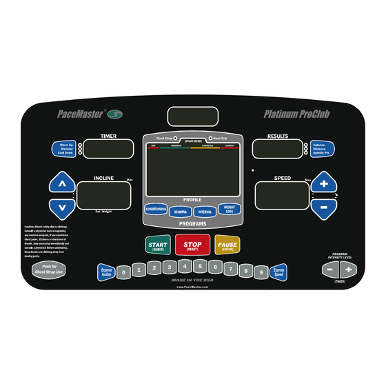
Page 19: The Pacemaster Platinum Proclub Control Panel
Although your PaceMaster has many advanced features to provide versatility in meeting exercise needs, basic operation is extremely easy. Basic operation involves setting your TIME and SPEED goals, then pressing the START button. Your PaceMaster will gradually accelerate to the set speed, maintain that speed until the timer counts to zero and then gradually come to a complete stop. During your exercise, your time remaining, current speed and incline, distance traveled, calories burned, Aerobic Points earned, and heart rate are displayed. - Page 20 THE PACEMASTER PLATINUM PROCLUB CONTROL PANEL (cont’d) START (QUICK) – 1) Use this button to QUICK START your workout with the press of one button. 2) In all other program modes, use this button to START your workout after the desired time, speed and incline have been entered.
-
Page 21: The Pacemaster Platinum Proclub Control Panel
THE PACEMASTER PLATINUM PROCLUB CONTROL PANEL (cont’d) Calories Distance Aerobic Pts RESULTS BUTTON – 1) Prior to beginning your workout, press this button to see the predicted caloric expenditure, Aerobic Points or distance for the workout you have chosen. 2) During your workout, press this button to select the desired feedback you want displayed;... -
Page 22: Operating Instructions
OPERATING INSTRUCTIONS Initially, you may want to keep both hands on the side rails until you feel comfortable walking on your PaceMaster. Once you feel comfortable, try removing your hands to let them swing naturally, as you would when walking outdoors. Always hold on to the side rail or front handle bar with one hand when operating the buttons of the control panel. -
Page 23: Quick Start
If a problem should occur, your PaceMaster can be stopped quickly by pulling on the magnetic safety cord to dislodge the key from the control panel. The treadmill will stop a bit more abruptly, but still gently enough to prevent you from being injured. This is an emergency procedure only and should not be used as the normal stopping procedure. -
Page 24: Timed Workout (Manual)
Elevation is adjusted in 0.5% increments. Step Five: Press and your PaceMaster will gradually accelerate until it reaches the entered speed. (QUICK) Step Six: To end your workout, either allow the timer to count down to zero or press the button. -
Page 25: Using The Programmed Workouts
USING THE PROGRAMMED WORKOUTS Step One: Stand on the running belt and attach the garment clip on the end of the magnetic safety key to your clothing. Insert the safety key into its recess on the control panel. Step Two: Press the Incline buttons to set your weight, then press the button. -
Page 26: Programmed Workout Profiles
PROGRAMMED WORKOUT PROFILES CONDITIONING Chest Strap Hand Grip Level Speed Incline EFFORT METER MODERATE STRENUOUS EXTREME PROFILE CONDITIONING LEVEL 4 STAMINA Chest Strap Hand Grip Level Speed Incline EFFORT METER MODERATE STRENUOUS EXTREME PROFILE STAMINA LEVEL 4 INTERVAL Chest Strap Hand Grip Level Speed... -
Page 27: Using A Wireless Chest Strap Transmitter
The wireless heart rate receiver on this model is designed to work with a Polar compatible chest strap. THE WIRELESS CHEST STRAP TRANSMITTER The PaceMaster Platinum ProClub treadmill comes equipped with a WIRELESS HEART RATE RECEIVER, which means, when wearing a Polar compatible chest strap, it displays pulse (number of heart beats per minute). -
Page 28: Exclusive Pacemaster Features
This formula is built into the PaceMaster computer to automatically calculate the number of AEROBIC POINTS you earn for each workout Dr. Cooper states in his book , The Aerobics Program For Total Well Being ; “The main idea of this system is that, in order to stay in good shape and move toward a goal of total well-being, a person must earn a certain number of points each week by doing a certain amount of aerobic exercise.”... - Page 29 EXCLUSIVE PACEMASTER FEATURES (cont’d) TIP: If you have selected your user ID, go to Step Four. Step Three: Press the Incline buttons to set your weight, then press the button. (ENTER) Step Four: WORKOUT INTENSITY LEVEL Enter the workout time using the...
-
Page 30: Care & Maintenance
Deck and Tread Belt Cleaning The running belt on your PaceMaster rides on a low friction deck. Performance will be compromised if any foreign matter comes between the tread belt and the deck. For this reason, extra care must be used in keeping the tread belt clean. Use a soft, damp cloth to remove dust, dirt and foreign matter from the area along side of the belt. -
Page 31: Centering The Tread Belt
Centering the Tread Belt To improve belt life, the belt should be reasonably centered. Run the treadmill at 2.5 mph for 3 minutes to allow the belt to settle in place. If the belt is NOT reasonably centered (no closer than 1/8” to the left or right deck shroud) follow the steps listed below. WARNING: Never make adjustments while the belt is moving. -
Page 32: Troubleshooting
Electronic Error Codes Your self-diagnostic PaceMaster treadmill has built in sensors that will determine the precise reason for a problem. If the onboard computer detects a problem, an error code will be displayed. If an error code appears during operation of your treadmill, do the following: •... -
Page 33: Elevation Error Codes
TROUBLESHOOTING (cont’d) CAUTION: Unplug your treadmill before attempting any cleaning, maintenance, or service. Error Code 117 This error will occur if the control panel is on and the user pushes the belt. If this error appears during a workout the user is manually pushing the belt faster than the set speed. -
Page 34: Hesitation Of The Belt
2 through 5. If you tighten the drive belt adjustment screw 1 1/2 turns and there is still hesitation (slippage) contact your authorized PaceMaster dealer. Tightening the drive belt adjustment screw more than 1 1/2... -
Page 35: Drive Belt Tension Adjustment
If a significant decrease in slippage was observed, go to step 2. If you tighten the tread belt 1 1/2 turns per side and slippage is still Figure 9 present, do not continue to adjust the tread belt tension. Contact your authorized PaceMaster dealer. -
Page 36: Frequently Asked Questions
FREQUENTLY ASKED QUESTIONS Q. Why is time displayed as a negative number (i.e. 1:15)? – A. The treadmill’s computer displays time in minutes and seconds (MM:SS) for workout times less than 1 Hour, and in hours and minutes ( H:MM) for workout times 1 hour or greater. 1:15 represents one hour and 15 minutes. -
Page 37: Pacemaster Technical Specifications
5 Years Frame, 2 Years Motor, 2 Years Parts, 1 Year Labor Operating Temperature Range 50º F to 100º F Manufacturer reserves the right to change the products specifications without notice. © PaceMaster LLC, 2010 PaceMaster is a registered trademark of PaceMaster LLC.
Need help?
Do you have a question about the Platinum ProClub and is the answer not in the manual?
Questions and answers
Hi why is my treadmill showing code 307
Error Code 307 on a PaceMaster Platinum ProClub treadmill indicates that there was no speed sensor signal at startup. To resolve this, check the speed sensor connection and wiring.
This answer is automatically generated