
Summary of Contents for Strider MX 3
- Page 1 S T R I D E R NURSING BEDS PFLEGEBETTEN OPERATING MANUAL MX 3 and MX 4 3 - w h e e l a n d 4 - w h e e l v e r s i o n Order number: E1-04-031-001...
- Page 3 S T R I D E R M X Introduction With the Strider MX, you have now purchased a product which has been manufactured in accordance with the newest technical capabilities and based on the highest operating comfort. We have placed great value on the simplest possible operation and long service life in both construction and material selection.
-
Page 4: Table Of Contents
6.2.4 Adjusting the backrest inclination ........27 6.3 Adjusting the headrest hight ............27 6.4 Adjusting the tiller angle ............. 28 Information about safe Strider driving ........... 29 7.1 Driving up inclines and down slopes .......... 29 7.2 Overcoming obstacles ............... 30 7.2.1 Driving Information –... - Page 5 8.9 Indicating ................... 42 8.10 Switching on the headlights ............43 8.11 Using the horn ................43 8.12 Switching off / parking the Strider ..........43 8.12.1 The wheel lock (4-wheel version only) ......44 Hazard lamps ................... 44 10.0 Pushing the Strider ................45 11.0 Attaching the shopping basket ............
- Page 6 Contents 14.0 Transporting the strider ..............54 14.1 Transport information ..............54 14.2 Transporting the complete strider (3 wheel version) ....54 14.3 Preparation for transport - separating component (4 wheel version) ................ 54 14.3.1 Working step summary ........... 55 14.3.2 Removing the seat ............
- Page 7 S T R I D E R M X Contents 18.5 Lighting - 4 wheel version ............86 18.5.1 Replacing bulbs in headlight and front indicators ..... 86 18.5.2 Replacing bulbs in rear light ..........87 18.5.3 Replacing bulbs in front/rear indicators ......88 18.6 Fuses ..................
-
Page 8: S T R I D E R M X
S T R I D E R M X Safety information 1.0 Safety instructions Symbols used This instruction manual contains the following symbols which are used to highlight special hazards in dealing with the product or information for simplifying the handling. Caution! This symbol identifies safety information which notifies you of hazards when dealing with the product. -
Page 9: General Information
S T R I D E R M X Safety information General Information Read the entire operating manual thoroughly before using the Strider! Ensure that: • the operating manual is read by all people who drive, care for and service the scooter. -
Page 10: Safety When Driving
S T R I D E R M X Safety information Safety when driving Risk of accidents! • Check correct functioning of the brakes and lighting unit (indicators, headlights) before every journey. • Always use lights when visibility is restricted, either by day or by night. -
Page 11: Safety During Transport, Assembly And Maintenance
S T R I D E R M X Safety information Danger due to unintentional movement! • Always turn the scooter off using the keyswitch if you: - want to get on or off - intend to stop for long periods - are putting the scooter away. -
Page 12: Safety When Handling Batteries
S T R I D E R M X Safety information Safety when handling batteries Fire hazard! • Do not cover the battery charger and ventilation slot while charging batteries. • Only use the battery charger in well-ventilated areas. Risk of accidents! •... -
Page 13: Versions
If any faults are apparent or components are missing, please contact Days Healthcare or your medical supplier. The following items are included in delivery in addition to the Strider: 1. Shopping basket 2. Two vehicle keys for switching the Strider on 3. Battery Charger 4. -
Page 14: Components
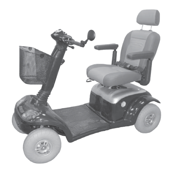
S T R I D E R M X Components 4.0 Components Speed switch Rear view Dashboard mirror The Strider Seat unit with controls with head- Tiller armrests Shopping Drive unit basket covers Indicators and rear light Steering wheel The dashboard - displays and controls... -
Page 15: Brief Instructions
It is imperative that you follow the instructions given in the main manual! Driving the Strider NOTE Before starting driving, adjust the seat height, the backrest and the armrests to a comfortable position. - Page 16 S T R I D E R M X Brief instructions 3.) Fasten the seat belt 4.) Switch on the Strider 5.) Check the battery charging state Issued: 24.02.2005...
- Page 17 S T R I D E R M X Brief instructions 6.) Adjusting the drive level Drive levels: H = 12 kph (8 mph) maximum driving speed L = 6 kph (4 mph) maximum driving speed 7.) Set the maximum speed = lowest possible driving speed for the required drive level...
- Page 18 S T R I D E R M X Brief instructions 9.) Braking = release drive lever (1) 10.) Direction indicators (1) Horn (2) Hazard lamps (3) Lights (4) Issued: 24.02.2005...
-
Page 19: Transporting The Strider
S T R I D E R M X Brief instructions Transporting the Strider Dismantling the Strider (stages 1 to 11) 1.) Remove the seat 2.) Remove the rear panelling 3.) Remove the lighting cable 4.) Separate the front connector 5.) Remove the battery plug... - Page 20 6.) Remove the battery belts and 7.) Removing the handbrake batteries cable 9.) Unlock the drive unit 8.) Fold the tiller down 11.) Remove the chassis 10.) Tilt the drive unit away Reassembling the Strider (Stages 11 to 1) Issued: 24.02.2005...
-
Page 21: Setting Up The Strider
S T R I D E R M X Adjusting the seat height 6.0 Setting up the Strider The following passage describes how to set up your Strider in order to ensure that you have a comfortable and safe drive. Adjusting the seat height... - Page 22 S T R I D E R M X Adjusting the seat height Press the locking device on the plug and disconnect the electric cable connecting plug (5) to the rear lights and rear indicators. Remove the rear panelling. Adjusting the seat height: Tools required: 2 x ring spanner, size 12 mm Removing the clamping...
- Page 23 Adjusting the seat height S T R I D E R M X Adjusting the seat The seat height (h) is adjusted using the support four holes (B1 - B4) in the seat support. Pull the seat support (9) out as far as the required height until the correct hole (B1-B4) appears in the seat tube hole (10).
- Page 24 - Engage the rear panelling onto the mountings (b) on the drive unit. - Align the rear panelling to the strider chassis (c). Inserting the seat: Pull the seat lock (3) and guide the seat into the seat support (4) from above.
-
Page 25: Adjusting The Seat Position
S T R I D E R M X Adjusting the seat position Tilt the backrest backwards: Tilt the backrest backwards Pull the locking lever (1) and move the backrest backwards to the required position (2). Let go of the locking lever and engage the locking mechanism by pushing the backrest slightly forwards and backwards. -
Page 26: Adjusting The Armrest Height
S T R I D E R M X Adjusting the seat position 6.2.3 Adjusting the armrest height Loosening the fixing Tools required: 1 x Allen key (size 5 mm) Loosen the Allen screw (4) and remove. The armrest height is adjusted using four holes in the armrest support (b). -
Page 27: Adjusting The Backrest Inclination
S T R I D E R M X Adjusting the seat position 6.2.4 Adjusting the backrest inclination The backrest inclination can be adjusted in three locking stages. 1st stage = drive setting 2nd stage = drive setting 3rd stage = not for driving! Tipping hazard! •... -
Page 28: Adjusting The Tiller Angle
S T R I D E R M X Adjusting the seat position Adjusting the tiller angle Always adjust the tiller so that you can reach all displays and controls easily at any time. The tiller can be variably adjusted. adjusting the tiller Push or pull the locking lever (1). -
Page 29: Information About Safe Strider Driving
- tight curves - inclines - ramps • take a trial run with the Strider in an area with no pedestrians, or in a closed-off area • always steer the Strider using both hands on the handlebars • always keep your feet in the foot area while driving the Strider... -
Page 30: Overcoming Obstacles
Tipping There is an increased danger of tipping hazard! when climbing or descending gradients if: • the Strider is loaded at the back and additionally • the backrest (captain’s seat) is leant towards the back and • the seat has been adjusted to its rear position. - Page 31 S T R I D E R M X Driving information Please observe the following points to make sure that your Strider doesn’t tip over while climbing obstacles: • don’t try to drive over obstacles which are too high example: kerbstones...
-
Page 32: Driving Information - Overcoming Kerbs
S T R I D E R M X Driving information 7.2.1 Driving Information – Overcoming kerbs Risk of accidents! Neogating kerbs needs some practice. • Please observe the maximum obstacle heights of 8 cm. • Please start practicing kerb climbing with small kerbs. Approach at a right angle Approach the kerb at a right angle. -
Page 33: Overload Protection - Motor Protection
If the motor is overloaded, the following happens: • the Strider becomes noticeably slower and then stops • the control system switches the Strider off To rectify this: Switch the scooter off and allow it to cool down for a few minutes. -
Page 34: Battery Charging State = Driving Range
• If the pointer has gone into the red area of the display after the journey, it will often show green after the Strider has been turned off for a long period. This does not indicate the actual charging state of the batteries! If the pointer is in the red area of the display at the end of the journey, the batteries must be charged before continuing the journey. -
Page 35: Driving Range
- driving with headlights For this reason, information about the driving range is only given as a guideline. The more experienced you are in using the Strider, the easier it will be for you to determine the driving range using the battery charging state. -
Page 36: Overdischarge Protection - Battery Protection
To rectify this: You must not drive the Strider any longer! Connect the Strider to the battery charger and charge the batteries for at least 12 hours. -
Page 37: Driving The Strider
8.0 Driving the Strider Getting on and off Please observe the following before getting on or off: • The Strider must be standing on firm, level and non-slippery ground. • The engaging lever for push mode must be in the drive position (see chapt. 9.0) •... -
Page 38: Seat Belt - Adjusting For Length And Putting On
S T R I D E R M X Driving the Strider NOTE! If you feel you are safe enough, you can of course get onto the Strider without turning the seat round. • You can lift up the armrest on the side where you are standing and then get on. -
Page 39: Turning The Seat
The switch (1) is located to the right of the tiller. Insert the key into the switch and turn it to the right to switch the Strider on. 8.4.1 Operation indicator and fault display Operation indicator This light shows that the Strider is switched on and ready for driving. -
Page 40: Adjusting The Speed
S T R I D E R M X Driving the Strider Adjusting the speed NOTE Use the adjustment facilities to adjust the speed to suit local conditions. Select a lower speed if you are driving through narrow gaps, on inclines or through crowds. -
Page 41: Before Driving
S T R I D E R M X Before driving Checks before driving: • Is the light working? Switch on to test! in working order! • Are the indicators working? Switch on to test! in working order! • Are the batteries charged? Check the display! in working order! •... -
Page 42: Brakes
- the Strider uses the motor to brake. Emergency braking = let go of the drive lever! The drive lever automatically returns to the central position if you let go. The Strider automatically brakes using the motor. 8.8.2 Using the handbrake Handbrake To use the handbrake, pull the brake lever (2) slowly towards the handlebar. -
Page 43: Switching On The Headlights
Always turn the Strider off using the keyswitch (1) if you: • want to get on or off. • intend to stop for long periods. Always remove the key from the keyswitch if you: • want to park the Strider and get off. Issued: 24.02.2005... -
Page 44: The Wheel Lock (4-Wheel Version Only)
S T R I D E R M X Hazard lamps 8.12.1 The wheel lock (4-wheel version only) The Strider can be secured against rolling away by using the wheel lock. Applying the brake: Wheel lock (1.) Pull the brake lever towards the handlebar (2.) Press the locking button in... -
Page 45: Pushing The Strider
(limit position). NOTES • Always switch the Strider off to push it. • If a pre-set speed is exceeded while you are pushing the Strider, the drive motor will switch on automatically and brake the Strider. Risk of accidents! •... -
Page 46: Charging The Batteries
24 hours. - The batteries can be charged overnight. • Switch the Strider off before charging the batteries. When is charging required? • the battery charge display is in the red area •... -
Page 47: Charging The Batteries
The jack socket (3) for connecting the battery charger is located on the left of the tiller. (1.) Connect the battery charger plug (4) to the Strider charging socket. (2.) Connect the battery charger mains plug (5) to a mains socket and switch on. -
Page 48: After Charging
12.3 After charging Removing the mains (1.) Switch off and Remove the battery plug charger plug from the mains socket. Removing the battery charger (2.) Pull the battery charger jackplug out of the Strider jack socket. Issued: 24.02.2005... -
Page 49: Things To Know
The entire power supply is taken over by two 12 V batteries. These are located below the motor cover under the seat. The batteries used in the Strider are known as batteries for cyclic use. Only enclosed maintenance-free deep cycle batteries are used. -
Page 50: The Auto Switch-Off
Things to know 13.3 The auto switch-off The auto switch-off automatically switches the Strider off after 20 minutes at a standstill. This protects the batteries from being discharged if the Strider was inadvertently not switched off. 13.4 The drive unit Drive unit... -
Page 51: Lighting
Anti tipping wheels 13.8 Anti tipping wheels The anti tipping wheels (1) reduce the danger of tipping during extreme manoeuvres when fixed to the rear of the Strider. It is not permitted to drive the Strider without anti tipping wheels. Issued: 24.02.2005... -
Page 52: Wheels And Tyres
To apply the brakes, simply let go off the drive lever which is then returned to its central position by a spring. The Strider is then braked by the drive motor. When the Strider is at a standstill or has been switched off, it is braked by a magnetic brake. -
Page 53: Driver´s Licence
S T R I D E R M X Things to know 13.11 Driver´s licence Not required! 13.12 Insurance As a scooter user you must be aware of the risks involved to both yourself and others. It is recommended that you take out third party insurance to cover you against any possible claims. -
Page 54: Transporting The Strider
Transporting the Strider 14.0 Transporting the strider 14.1 Transport information Depending on the size of the transport vehicle, the Strider can be dismantled in a few steps so that it can also be easily transported in smaller vehicles. When transporting, take particular care to ensure that the batteries are securely fastened and make sure components cannot tip over. -
Page 55: Working Step Summary
S T R I D E R M X Transporting the Strider In just a few steps you can dismantle the Strider down to the following components to make it ready for transport: 1. Chassis 2. Batteries 3. Drive unit 4. -
Page 56: Removing The Rear Panelling
Transporting the Strider 14.3.3 Removing the rear panelling Removing the rear panelling Pull the rear panelling off the Strider upwards. Press the locking device (A) on the plug and disconnect the electric cable connecting plug (5) to the rear lights and rear indicators. -
Page 57: Removing The Handbrake Cable
S T R I D E R M X Transporting the Strider 14.3.5 Removing the handbrake cable Remove the brake cable wing nut at the brake lever (9). Remove the brake cable mounting wing nut (10). Pull the brake cable (11) and pressure spring (12) out of the brake lever (9) and pull the cable seat out. - Page 58 S T R I D E R M X Transporting the Strider Unlocking the drive unit Open the clamping bolt clamping lever (15) and fold the clamping bolt upwards. Tilt the drive unit away Tilt drive unit to the rear onto the anti tip wheels (16).
-
Page 59: After Transport - Reassembly
S T R I D E R M X Transporting the Strider 14.4 After Transport - Reassembly Working step summary: 1. Re-couple the drive unit 2. Fold the tiller up again 3. Inserting the brake cable 4. Insert the batteries and secure with the straps 5. -
Page 60: Folding The Tiller Up
S T R I D E R M X Transporting the Strider NOTE The clamping bolts fit automatically into the chassis receptacle (4). If this is not the case, the clamping bolts will have to be adjusted. You can find information about adjustment in the chapter 18.3.1. -
Page 61: Inserting The Brake Cable
S T R I D E R M X Transporting the Strider 14.4.3 Inserting the brake cable Inserting the brake cable Insert the brake cable into the cable seat (9) and screw tight with the wing nut (10). Threading the brake... -
Page 62: Reinserting The Batteries
S T R I D E R M X Transporting the Strider Screwing down the Screw the brake cable wing nut (13) brake cable on and adjust the handbrake. Caution: accident hazard After a new brake cable has been inserted, the handbrake must be adjusted. -
Page 63: Fixing The Rear Panelling
S T R I D E R M X Transporting the Strider Plug in the battery cable connecting Plug in the battery plugs plugs (12). Connecting the light cable 14.4.5 Fixing the rear panelling Plug in the light and indicator cable connecting plug (13). -
Page 64: Fitting The Seat
S T R I D E R M X Transporting the Strider 14.4.6 Fitting the seat Fitting the seat Pull the seat lock (14) and guide the seat into the seat support (15) from above. Let go the seat lock and engage the rotational adjustment by turning the seat one way then the other. -
Page 65: Maintenance And Inspection
S T R I D E R M X Cleaning 16.0 Maintenance and Inspection If you find any faults on your scooter during maintenance which are not covered by the repair information, please contact your dealer. Always remove faulty scooters from operation and secure them against unauthorized use (remove key). -
Page 66: Annual Inspection - Inspection Timetable
S T R I D E R M X Maintenance and inspection 16.3 Annual inspection - inspection timetable Take your scooter once per year to your dealer for an inspection. He will have the necessary tools and experience to service your scooter correctly. - Page 67 S T R I D E R M X Maintenance and inspection Description Assessment (Component / inspection for) Defective Component : Tiller Panelling / no damage fixed securely Grip rubbers / no damage fixed securely Tiller, folding mechanism / no play in joint functions easily Component : chassis Connections /...
- Page 68 S T R I D E R M X Maintenance and inspection Description Assessment (Component / inspection for) Defective Component : Handbrake Handbrake / all components no damage safe function equal adjusted both sides easy movement bowdencable Component : Displays and controls, electric system, electronic system Dashboard switches / no damage safe function...
- Page 69 Easy functioning over the entire lever movement Returns to central position after releasing from any position Secure blockage of magnetic brakes when lever is in central position (Strider can not be pushed) Component : Drive Motor, drive / no damage fixed securely drive noise...
-
Page 70: Troubleshooting
Switch the Strider off. Check the main plug (1) and the battery plug (2) for a tight fit. Switch the Strider on again. If the fault occurs again, you will find information about troubleshooting and fault remedy in the lists in Pos. 17.2 and 17.3. - Page 71 S T R I D E R M X Troubleshooting Fault Cause Remedy Scooter does not run / Check battery Charge the batteries Operation indicator blinking charge display (chapter 12.0) rapidly (fault display) (Batteries discharged) Scooter switched Switch to drive to push mode mode (chapter 10.0) Connecting plugs...
- Page 72 S T R I D E R M X Troubleshooting Fault Cause Remedy Battery charge display moves Batteries Charge the batteries rapidly to discharged during discharged (chapter 12.0) journey Batteries defective Visit your dealer Motor jerks during driving Motor defective Scooter not Lighting / indicators not working Switch the scooter on...
- Page 73 S T R I D E R M X Troubleshooting Fault Cause Remedy Operation indicator blinking (fault display) ..blinking slowly Drive lever Release drive lever when switching on pressed down while switching on ... blinking slowly Battery voltage Finish your journey as during the journey too low...
-
Page 74: Repairs
The Strider must be lifted in order to carry out certain work such as removing the wheels. Before you lift the Strider, make sure you prevent it rolling away by wedging it securely. -
Page 75: Mechanics
S T R I D E R M X Repairs - mechanics 18.3 Mechanics 18.3.1 Adjusting the drive lock clamping bolts The clamping tightness is adjusted by turning the clamping bolts. The clamping tightness should be set so that the clamping lever can be closed by hand without requiring too much force. - Page 76 S T R I D E R M X Repairs - mechanics Checking the clamping bolt setting. Checking the setting It must: • automatically fall into the chassis receptacle (3). • be able to be locked by hand without use of great force (4). Checking alignment Checking the clamping lever alignment.
-
Page 77: Wheels - Removal And Replacement - 3-Wheel Version
1 x ring spanner, size 17 mm Removing the front wheel: Front wheel Secure the Strider against rolling away. Lift the front end of the Strider and support it (see chapter 19.0). Remove the wheel fixing protective cap (1) with a screwdriver. -
Page 78: Wheels - Removal And Replacement - 4-Wheel Version
Removing the wheels: Front wheel Loosen the self-locking nut (2) for the wheel fastening (size 19 mm). Secure the Strider against rolling away. Lift the Strider and support it (see chapter 19.0). Remove the self-locking nut for the wheel fastening (size 19 mm). - Page 79 Push the wheel onto the stem (3) as far as the wheel stop. Screw the wheel fixing self-locking nut (4) and tighten it (size 19 mm). Lower the Strider. Retighten the self-locking nut (3). Press the protective cap onto the wheel fixing nut.
- Page 80 Locating the washer Place the washer (8). Securing the rear wheel Screw the wheel fixing self-locking nut (9) and tighten it (size 19 mm). Lower the Strider. Tighten the self-locking nut. Press the protective cap onto the wheel fixing nut. Issued: 24.02.2005...
-
Page 81: Replacing The Inner Tube / Tyre
Dismantling the wheel rims: Loosen the three nuts (2) with a socket Reassembling the spanner (size 12 mm) and remove Strider wheel together with the lock washers (3). Separate the wheel hub (4; front wheel) / brake drum (5; rear wheel) from the wheel rim. -
Page 82: Adjusting The Handbrake
S T R I D E R M X Repairs - mechanics at the handlebars. 18.3.5 Adjusting the handbrake Secure the Strider against rolling away. Raise the side with the braked wheel and support (see Chapter 19.0). Before adjusting the brake, check that the handle adjustment (1) is screwed fully in. - Page 83 S T R I D E R M X Repairs - mechanics Braking adjustments - 4-wheel version: Adjustment on rear wheel Turn the brake cable wing nut (4) on the rear wheel until resistence can be felt at the brake lever after about 1.5cm of its operating distance.
-
Page 84: Lighting - 3 Wheel Version
S T R I D E R M X Repairs - lighting 18.4 Lighting - 3 wheel version Tools required: 1 x screwdriver; Phillips head No. 2 18.4.1 Replacing bulb in headlight Bulb version used: 24 V / 10 Watt Removing the lamp lens Loosen the fixing screws (1) and remove the front light lens (2). -
Page 85: Replacing Bulbs In Front Indicators
S T R I D E R M X Repairs - lighting 18.4.2 Replacing bulbs in front indicators Bulb version used: 24 V / 10 Watt Removing the indicator lens Loosen the fixing screw (1) and remove the indicator lens (2). Removing the bulb Remove the bulb: (1.) Press the bulb in lightly and remove... -
Page 86: Lighting - 4 Wheel Version
S T R I D E R M X Repairs - lighting 18.5 Lighting - 4 wheel version Tools required: 1 x screwdriver; Phillips head No. 2 18.5.1 Replacing bulbs in headlight and front indicators Bulb versions for headlight and direction indicators: 24 V / 10 Watt Loosen the fixing screws (1) and remove Removing the lamp lens... -
Page 87: Replacing Bulbs In Rear Light
S T R I D E R M X Repairs - lighting 18.5.2 Replacing bulbs in rear light Bulb version used: 24 V / 5 Watt (glass base lamp) Removing the lamp lens Loosen the fixing screw (1) and remove the front or rear light lens. -
Page 88: Replacing Bulbs In Front/Rear Indicators
S T R I D E R M X Repairs - lighting 18.5.3 Replacing bulbs in front/rear indicators Bulb version used: 24 V / 10 Watt NOTE Removing the lamp lens The working sequence for front and 3-Wheel-Version rear indicators is the same, and is described using photographs of the rear lights. -
Page 89: Fuses
18.6 Fuses A wiring diagram with fuse sizes is located on the control unit cover. The Strider is fitted with the following fusible fuses. (1) 2 A fuse = power supply to tiller head. (2) 10 A fuse = charging socket... - Page 90 S T R I D E R M X Repairs - fuses 3 types of battery fuses are used. Battery fuse: type 1 Type 1: • 70 A fuse = plug-in fuse - Fuse holder is in the positive pole cable of the batteries To replace Fuse: Open fuse holder.
- Page 91 S T R I D E R M X Repairs - fuses Type 3: Battery fuse: type 3 • 70 A fuse = strip fuse - Fuse holder at the plus pole of the batteries (illustration without insulating cap) To replace Fuse: Remove insulating cap of the fuse holder.
-
Page 92: Batteries
S T R I D E R M X Repairs - batteries 18.7 Batteries Only replace the batteries with the following battery types: 12 V / 70 AH, liquid acid deep cycle batteries. You may not use wet cell batteries with detachable cover caps. Risk of accidents! •... -
Page 93: Refitting Battery Cables
Tools required: 2 x ring spanner; size 10 mm Remove the batteries from the Strider as described in chapter 14.3.4. Refitting the battery cable: First (1) loosen the terminal on the... -
Page 94: Temporary Storage
S T R I D E R M X Temporary storage 19.0 Temporary storage Front support, 3 wheel If you are not intending to use your Strider version for longer periods (e.g. over the winter, you should prepare it as follows: Remove soiling and dust. -
Page 95: Specifications
Maximum climable incline ....... 12° (1:5) Maximum climable obstacle ......100 mm Total weight (ready for driving incl. batteries) ...... 120 kg / MX 3 ..............135 kg / MX 4 Weight heaviest part ........52.5 kg / MX 3 ........ -
Page 96: Dimensions 3-Wheel Version
S T R I D E R M X Appendix - dimensions Bulbs: Headlight ............24 Volt / 5 Watt Rear light ............24 Volt / 5 Watt Front indicator ..........24 Volt / 10 Watt Rear indicator ..........24 Volt / 10 Watt 20.2.2 Dimensions 3-wheel version Issued: 24.02.2005... -
Page 97: Dimensions 4-Wheel Version
S T R I D E R M X Appendix - dimensions 20.2.3 Dimensions 4-wheel version Issued: 24.02.2005... -
Page 98: Torque For Fixing Screws
S T R I D E R M X Appendix - tightening torques 20.3 Torque for fixing screws Front wheel central self-locking Nut (M10*p1.25) = 50 Nm Rear wheel central self-locking Nut (M12*p1.25) = 60 Nm Front / rear wheel rim, 3 nuts (M8*p1.25) = 33 Nm General torque for nuts and bolts: = 4.5 to 6 Nm... -
Page 99: Warranty Information
S T R I D E R M X Warranty 21.0 Warranty information The Strider Model MX 3 and MX 4 scooters carry a 12 months warranty from date of purchase. Important! • During the warranty period any parts that have become defective due to faulty workmanship or material will be repaired or replaced without charge by Days Healthcare supplier / dealer. -
Page 100: Annual Inspections Carried Out
S T R I D E R M X 22.0 Annual inspections carried out Date:_______ Date:_______ Dealer´s stamp Dealer´s stamp __________________________ __________________________ (Signature) (Signature) Date:_______ Date:_______ Dealer´s stamp Dealer´s stamp __________________________ __________________________ (Signature) (Signature) Date:_______ Date:_______ Dealer´s stamp Dealer´s stamp __________________________ __________________________ (Signature) - Page 102 (Dealer´s stamp) Days Healthcare Limited Bridgend Ind Est BridgendCF31 3TP (t) + 044 (0)1656.65 74 95 (f) + 044 (0)1656.76 71 78 (e) sales@dayshealthcare.com (w) www.dayshealthcare.com...
Need help?
Do you have a question about the MX 3 and is the answer not in the manual?
Questions and answers