Table of Contents
Advertisement
Quick Links
Advertisement
Table of Contents

Summary of Contents for Redlake MASD MegaPlus 4.2i
- Page 1 Manual No. 91000058-003 Revision A October 1, 2001 â The MegaPlus Model 4.2i Camera User’s Manual Redlake MASD, Inc. 11633 Sorrento Valley Road San Diego, California 92121-1097 Telephone: 800-854-7006 (USA and Canada only) Outside the USA: 858 481-8182 Fax: 858-481-6254.
-
Page 2: Related Documents
The information in this manual is for information purposes only and is subject to change without notice. Redlake MASD, Inc. makes no warranty of any kind with regards to the information contained in this manual, including but not limited to implied warranties of merchantability and fitness for a particular purpose. - Page 3 LIFE SUPPORT APPLICATIONS POLICY MegaPlus cameras are not authorized for and should not be used within life support systems without the specific written consent of Redlake MASD, Inc. NON-CRITICAL MEDICAL APPLICATIONS MegaPlus cameras must be grounded to building earth ground while operating. This camera has passed IEC 601 class B standards.
-
Page 4: Table Of Contents
REDLAKE MASD, INC. TABLE OF CONTENTS INTRODUCTION ....................... 1-1 Introduction........................1-1 How to Use This Manual ....................1-1 CONTROLS AND CONNECTORS ................... 2-1 Camera........................... 2-1 2.1.1 Mounting the Camera ..................... 2-1 2.1.2 Attaching the Lens ....................2-1 Camera Rear Panel ....................... 2-2 2.2.1... - Page 5 LIST OF FIGURES Figure 2-1. Camera Body ......................2-1 Figure 2-2. C-Mount Lens Length Limit..................2-1 Figure 2-3. 4.2i Rear Panel ......................2-2 Figure 2-4. 4.2i Cable Types ......................2-3 Figure 2-5. Component Connection Diagram................2-4 Figure 3-1. Wedge Display ......................3-9 Figure 4-1.
- Page 6 REDLAKE MASD, INC. THIS PAGE INTENTIONALLY LEFT BLANK 91000058-003 Revision A 10/01/01...
-
Page 7: Introduction
1. INTRODUCTION 1.1 Introduction The Redlake MASD, INC. MegaPlus Camera, Model 4.2i, is a high-resolution solid-state camera designed for scientific and industrial imaging applications. The system consists of a DC powered Camera Head with a 68 pin digital interface. There are no manual user controls on the camera, however the camera is operated by commands sent through a serial communication link. - Page 8 REDLAKE MASD, INC. Chapter 1 contains an introduction to the MegaPlus camera, an explanation of this manual, some general precautions, and a warranty statement. Chapter 2 explains the function of the controls and connectors of the MegaPlus Camera. Chapter 3 is intended to give the user some insight into how to choose the correct mode of operation for this MegaPlus camera.
- Page 9 • Shipping damage is not covered by this warranty. The purchaser has the responsibility to place a claim of damage in shipment with the carrier. REDLAKE MASD, INC. MAKES NO OTHER WARRANTIES, EXPRESSED, IMPLIED, OR OF MERCHANTABILITY FOR THIS EQUIPMENT. IF THIS CAMERA DOES NOT FUNCTION PROPERLY DURING THE WARRANTY PERIOD, REDLAKE WILL REPAIR IT WITHOUT CHARGE ACCORDING TO THE TERMS STATED ABOVE.
- Page 10 REDLAKE MASD, INC. THIS PAGE INTENTIONALLY LEFT BLANK 91000058-003 Revision A 10/01/01...
-
Page 11: Controls And Connectors
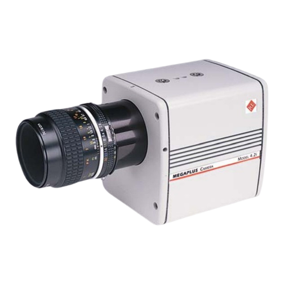
® MegaPlus Model 4.2i 2. CONTROLS AND CONNECTORS 2.1 Camera NOTE: A lens cap is installed on each camera to keep dust from getting on the optical sensor or components when it is shipped. Remove the lens cap and install your lens in a dust free environment. -
Page 12: Camera Rear Panel
REDLAKE MASD, INC. Figure 2-3. 4.2i Rear Panel 2.2 Camera Rear Panel 2.2.1 Digital Interface This is a 68-pin, high density, dual row, D type connector that interfaces the MegaPlus Camera to a frame grabber board and serial communication interface for camera control. The frame grabber board processes and displays video from the camera. -
Page 13: Cables
® MegaPlus Model 4.2i 2.3 Cables There are three different cables available to connect the MegaPlus Camera to your computer, as shown in Figure 2-4 below. Figure 2-4. 4.2i Cable Types 91000058-003 Revision A USER’S MANUAL... -
Page 14: Hardware Setup
REDLAKE MASD, INC. 2.4 Hardware Setup Follow the instructions supplied by the frame grabber manufacturer when you are using their cables to install your camera. If using Redlake supplied cables, connect the camera as shown in Figure 2-5 below. Figure 2-5. Component Connection Diagram... -
Page 15: Routine Maintenance
® MegaPlus Model 4.2i 2.5 Routine Maintenance There are no user serviceable parts in the camera. Should the shutter malfunction, the camera must be returned to the factory for repair. The lens should be cleaned according to good photographic practices. This will help keep your camera producing top quality pictures. - Page 16 REDLAKE MASD, INC. THIS PAGE INTENTIONALLY LEFT BLANK 91000058-003 Revision A 10/01/01...
-
Page 17: Camera Operation
3. CAMERA OPERATION 3.1 Introduction The MegaPlus Camera, Model 4.2i does not have any manual controls. Camera operation is accomplished by commands sent to the camera through a serial data link from a personal computer. In this chapter we will present the various operating modes of the camera with an explanation of the function followed by the command sequence that must be transmitted by the computer. -
Page 18: Trigger
REDLAKE MASD, INC. 3.4.1 Trigger Each exposure is started by a signal connected to the EXPOSE input pins of the “Digital Interface” connector on the rear panel of the camera. The exposure command sets the exposure time and, indirectly, the frame rate. -
Page 19: Shutter
® MegaPlus Model 4.2i 3.5 Shutter The MegaPlus Camera may be operated with the shutter on or off. When the shutter is off, the shutter blades can be locked open or closed. The shutter is controlled by the SHE command in the CONTINUOUS, CONTROL and TRIGGER modes of operation. -
Page 20: Exposure
REDLAKE MASD, INC. 3.6 Exposure This command sets the exposure time of the camera in increments of one millisecond. The exposure times can be any value between one millisecond and one hundred seconds. This exposure time setting affects the CONTINUOUS and TRIGGER modes only. The camera produces the most uniform picture when the exposure time is between 50 and 200 milliseconds. -
Page 21: Trigger
Transfer frame and then idle. TRM N HIGH Transfer frame and then idle TRM N Expose. NOTE: Trigger must be set to positive, TRM P, if you are using a frame grabber designed for the MegaPlus 4.2i camera. 91000058-003 Revision A USER’S MANUAL... -
Page 22: Gain
REDLAKE MASD, INC. 3.8 Gain The gain of the camera is variable in 2dB steps between 0dB and 24dB. The normal gain position is 6dB. 0dB halves the gain, 12dB multiplies the gain by 2, 18dB multiplies the gain by 4 and 24dB multiplies the gain by 8. -
Page 23: Strobe Polarity
Makes the strobe output a low going pulse. NOTE: The STROBE OUTPUT must be set to positive, STP P, if you are using a strobe designed for use with the MegaPlus 4.2i camera. 3.11 Defect Correction Occasionally, sensors are not perfect and have some areas that react differently to light. These problem pixels are usually seen as a column that is different in intensity than the immediately adjacent area. -
Page 24: Save
REDLAKE MASD, INC. 3.13 Save TYPE IN: RESPONSE EXPLANATION CR-LF Saves the current camera settings to EEPROM; these settings will be recalled by a RESET or by turning the camera power on. NOTE: The EEPROM used by the SAVE command has a finite life of roughly 10,000 erase and program cycles. -
Page 25: Display Wedge
® MegaPlus Model 4.2i Figure 3-1. Wedge Display 3.16 Display Wedge The wedge command displays linearly increasing gray scales in each quadrant of the image as shown in Figure 3-1. This function is useful for aligning the camera image to a frame grabber. - Page 26 REDLAKE MASD, INC. THIS PAGE INTENTIONALLY LEFT BLANK 91000058-003 Revision A 3-10 10/01/01...
-
Page 27: Interface Specifications
4. INTERFACE SPECIFICATIONS 4.1 Introduction Chapter four gives you the information needed to interface the MegaPlus Camera, Model 4.2i to a frame grabber device. The relationship between the video outputs and the synchronization outputs of the camera are presented in the following order: •... -
Page 28: Control Inputs
REDLAKE MASD, INC. 4.5 Control Inputs The control input EXPOSE is provided as a means of externally controlling the exposure of the camera. This input is designed to accept RS-422 differential or, for backwards compatibility, single ended TTL. To drive this input differentially, connect both the (+) and (-) inputs to an RS-422 driver. -
Page 29: Figure 4-1. Digital Interface Connector
® MegaPlus Model 4.2i Table 4-2. Digital Interface Connector Pinout (On Rear of Camera) SIGNAL NAME SIGNAL NAME SOURCE GROUND GROUND Camera MSB (+) MSB (-) Camera MSB-1 (+) MSB-1 (-) Camera MSB-2 (+) MSB-2 (-) Camera MSB-3 (+) MSB-3 (-) -
Page 30: Figure 4-2. 68-Pin Digital Interface Cable
REDLAKE MASD, INC. (For use with 8 or 10 bit, RS422 Cameras) (Refer to Table 4-2 for Pinout) Figure 4-2. 68-Pin Digital Interface Cable 91000058-003 Revision A 10/01/01... -
Page 31: Figure 4-3. 37-Pin Connector
® MegaPlus Model 4.2i Table 4-3. 37-Pin Frame Grabber Cable Pinout SIGNAL NAME SIGNAL NAME SOURCE PIX DATA STRB (+) PIX DATA STRB (-) Camera LINE ENA (+) LINE ENA (-) Camera FRME ENA (+) FRME ENA (-) Camera GROUND... -
Page 32: Figure 4-5. 9-Pin Pc Com Port/37-Pin Frame Grabber Cable
REDLAKE MASD, INC. (Refer to Tables 4-3 and 4-4 for Pinouts) Figure 4-5. 9-Pin PC COM Port/37-Pin Frame Grabber Cable 91000058-003 Revision A 10/01/01... -
Page 33: Figure 4-6. 68-Pin Frame Grabber Connector
® MegaPlus Model 4.2i Table 4-5. 68-Pin Frame Grabber Interface Cable Pinout SIGNAL NAME SIGNAL NAME SOURCE GROUND GROUND Camera MSB (+) MSB (-) Camera MSB-1 (+) MSB-1 (-) Camera MSB-2 (+) MSB-2 (-) Camera MSB-3 (+) MSB-3 (-) Camera... -
Page 34: Figure 4-7. 9-Pin Pc Com Port/68-Pin (And 37-Pin) Frame Grabber Cable
REDLAKE MASD, INC. (Refer to Table- for Pinout) Figure 4-7. 9-Pin PC COM Port/68-Pin (and 37-Pin) Frame Grabber Cable 91000058-003 Revision A 10/01/01... -
Page 35: Sensor Specifications
® MegaPlus Model 4.2i 4.7 Sensor Specifications Table 4-6. Sensor Specifications ITEM DESCRIPTION Imaging Device Solid-state charge-coupled device (CCD); front illuminated full-frame architecture Total Pixel Clock Count 4,849,664 (2,368H x 2,048V) Light-Sensitive Pixels 4,147,276 (2,029H x 2,044V) Elements Transferred Per Line... -
Page 36: Frame Rate Data
REDLAKE MASD, INC. 4.8 Frame Rate Data 4.8.1 Frame Rates The frame rate of the camera is the number of images that can be taken per unit of time. The camera must transfer a full frame before it is able to make a new exposure and transfer the new frame. -
Page 37: Timing Waveforms
® MegaPlus Model 4.2i 4.9 Timing Waveforms 4.9.1 Exposure Timing The start and stop of exposure time are synchronized with the falling edge of LINE ENA (+). The exposure time interval, whether generated internally or externally, is sampled at the falling edge of LINE ENA (+). -
Page 38: Frame Timing
REDLAKE MASD, INC. 4.9.2 Frame Timing The FRAME ENABLE signal is low while the array is exposed. The duration of this low state is variable and includes the user defined exposure time. A complete frame of video data is transferred to the camera outputs while FRAME ENA (+) is high. -
Page 39: Line Enable
® MegaPlus Model 4.2i 4.9.3 Line Enable This is the Horizontal Sync for the camera. This signal runs continuously to allow external equipment to “phase lock” with the camera if desired. It is not affected by the camera mode or by any state the camera may be in (idle, exposing, or transferring). -
Page 40: Specifications
REDLAKE MASD, INC. 4.10 Specifications 4.10.1 Video Performance Black Level: Clamped to black reference at the start of each frame. Gamma: Unity. Scanning: Non-Interlaced progressive scan Synchronization: Internal. Dynamic Range: Greater than 65dB at the input of the A/D Converter.
Need help?
Do you have a question about the MegaPlus 4.2i and is the answer not in the manual?
Questions and answers