Table of Contents
Advertisement
TM
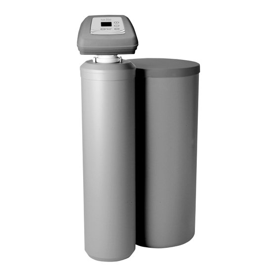
Model TB-30
How to install, operate
and maintain your Demand
Controlled Water Softener
If you have any questions about system
programming, operation or maintenance,
call toll free:
1-800-689-4571
Monday - Friday, 8:30 am - 6:00 pm EST
or Saturday 9:00 am - 3:00 pm EST
or visit us online at:
www.truebluewatersolutions.com
When you call, please be prepared to provide
the model, date code and serial number of your
product, found on the rating decal, located on
the back of the controller top cover.
Systems tested and certified by NSF International
against NSF/ANSI Standard 44
for hardness reduction and efficiency.
Manufactured for Defender Security Company by
Printed on recycled paper
Ecodyne Water Systems
1890 Woodlane Drive
Woodbury, MN 55125
7330189 (Rev. C 8/16/11)
Advertisement
Table of Contents
Troubleshooting

Subscribe to Our Youtube Channel
Summary of Contents for True blue power TB-30
- Page 1 Model TB-30 How to install, operate and maintain your Demand Controlled Water Softener If you have any questions about system programming, operation or maintenance, call toll free: 1-800-689-4571 Monday - Friday, 8:30 am - 6:00 pm EST or Saturday 9:00 am - 3:00 pm EST or visit us online at: www.truebluewatersolutions.com...
-
Page 2: Table Of Contents
This warranty applies to consumer-owned installations only. Manufactured by Ecodyne Water Systems, 1890 Woodlane Drive, Woodbury, MN 55125, for Defender Security Company, 3750 Priority Way South Drive, Suite 200, Indianapolis, IN 46240. -
Page 3: Specifications & Dimensions
Specifications & Dimensions Model TB-30 Model Code tb-30 11,800 @ 2.3 lbs. Rated Softening Capacity (Grains @ Salt Dose) 25,300 @ 7.4 lbs. 30,200 @ 12.5 lbs. Rated Efficiency (Grains/Pound of Salt @ Minimum Salt Dose) 5,130 @ 2.3 lbs. -
Page 4: Inspect Shipment
Inspect Shipment The parts required to assemble and install the water Remove and discard (or recycle) all packing materials. softener are included with the unit. Thoroughly check To avoid loss of small parts, we suggest you keep the the water softener for possible shipping damage and small parts in the parts bag until you are ready to use parts loss. -
Page 5: Installation Requirements
Installation Requirements LOCATION REQUIREMENTS PLUMBING CODES Consider all of the following when selecting an installa- All plumbing must be completed in accordance with tion location for the water softener. national, state and local plumbing codes. = Do not locate the water softener where freezing temperatures occur. -
Page 6: Typical Installation Illustrations
Typical Installation Illustrations Soft CROSSOVER Water Use if water supply flows from the left. Include single or 3-valve bypass. Hard Water Hard Soft Water Water From Hard Water to Softener Softener outside faucets Outlet Inlet 120 Volt Outlet INSTALLATION USING 3-VALVE BYPASS Soft 1”... -
Page 7: Installation Instructions
Installation Instructions 1. TURN OFF WATER SUPPLY Clip (2) a. Close the main water supply valve near the well Plastic pump or water meter. installation b. Shut off the electric or fuel supply to the water adaptors OUTLET heater. c. Open high and low faucets to drain all water from the house pipes. - Page 8 Installation Instructions 4. COMPLETE INLET AND OUTLET PLUMBING Ground Clamp Pipe fittings must be 3/4” minimum. Use: = Copper pipe = Threaded pipe Inlet / Outlet = PEX (Crosslinked Polyethylene) pipe Pipes FIG. 11 = CPVC plastic pipe = Other pipe approved for use with potable water 6.
- Page 9 Installation Instructions 7. INSTALL SALT STORAGE TANK OVER- 9. TEST FOR LEAKS FLOW FITTINGS AND HOSE To prevent air pressure in the water softener and plumbing system, complete the following steps in a. Insert the rubber grommet into the 3/4” diameter order: hole in the salt storage tank sidewall (See Figure 14).
- Page 10 Installation Instructions 10. ADD WATER AND SALT TO THE SALT 13. SANITIZE THE WATER SOFTENER / STORAGE TANK SANITIZE AFTER SERVICE 1. Using a container, add about three gallons of clean Care is taken at the factory to keep your unit clean and water into the salt storage tank.
-
Page 11: Programming The Electronic Controller
NOTE: If “HARDNESS” and a number do not show in When the transformer is plugged into the electrical the display, press the SELECT button a few outlet, a model code (tb-30) and a test number times until they do. (example: J2.0), are briefly shown in the display. - Page 12 Programming the Electronic Controller OPTIONAL RECHARGE CONTROLS continued from previous page Sometimes a manually initiated regeneration (re- charge) may be desired or needed. Two examples: = You have used more water than usual (guests, extra washing, etc.) and you may run out of soft water before the next scheduled regeneration.
-
Page 13: Controller Features / Options
Controller Features / Options OPTIONAL SETTINGS: 2. Press SELECT again to display the “Recharge Days” screen. SALT EFFICIENCY MAXIMUM DAYS BETWEEN REGEN- ERATIONS 97% FEATURE 12 / 24 HOUR CLOCK FIG. 28 BACKWASH & FAST RINSE TIMES 1. To set any of these options, press and hold SELECT MAXIMUM DAYS BETWEEN REGENERATIONS: for 3 seconds until “000 - -”... -
Page 14: Controller Features / Options
Controller Features / Options PROGRAM MEMORY 4. Press SELECT again to display the “12 or 24 hr” screen. If electrical power to the softener is interrupted, the time display is blank, but the electronic controller keeps correct time for about 6 hours. When power is restored, you must reset the present time only if the display is flashing. -
Page 15: Routine Maintenance
Routine Maintenance ADDING SALT CLEANING THE NOZZLE & VENTURI Lift the salt storage tank cover and check the salt level A clean nozzle & venturi (See Figure 34) is a necessity frequently. If the water softener uses all the salt before for the water softener to work properly. -
Page 16: Troubleshooting
Troubleshooting Guide PROBLEM CAUSE CORRECTION No soft water No salt in the storage tank. Add salt and then initiate a “Recharge Now”. Salt is “bridged” (a layer of salt in the Break salt bridge, as described on the previous salt storage tank has hardened). page, and then initiate a “Recharge Now”. -
Page 17: Troubleshooting
Troubleshooting AUTOMATIC ELECTRONIC DIAGNOSTICS MANUALLY INITIATED ELECTRONIC DIAGNOSTICS The electronic controller has a self-diagnostic function for the electrical system (except input power and 1. To enter diagnostics, press and hold the SELECT water meter). The computer monitors the electronic button until “000 - -” appears in the display. components and circuits for correct operation. - Page 18 RESETTING TO FACTORY DEFAULTS: 6. Press the SELECT button and hold in for 3 sec- onds until the model code (tb-30) shows in the dis- To reset the electronic controller to its factory default play. This code identifies the softener model. If for all settings (time, hardness, etc.):...
- Page 19 Troubleshooting MANUAL ADVANCE REGENERATION CHECK 2. After observing fill, press the RECHARGE button to move the softener into brining. A slow flow of This check verifies proper operation of the valve water to the drain will begin. Verify brine draw from motor, brine tank fill, brine draw, regeneration flow the brine tank by shining a flashlight into the rates, and other controller functions.
-
Page 20: Exploded View & Parts List
Softener Exploded View (Model TB-30) Valve Assembly See Pages 22 & 23 for parts... - Page 21 Softener Parts List (Model TB-30) Part No. Description Part No. Description 7112971 Shroud 7155115 Brinewell Cover 7026196 Base 7082150 Wing Nut, 1/4-20 7176292 Clamp Section (2 req.) 7100819 Brinewell 7088033 Retainer Clip (2 req.) 7003847 O-Ring O-Ring Seal Kit, 7148875...
- Page 22 Valve Exploded View (Model TB-30) Wear Strip Seal Cross-section View...
- Page 23 Valve Parts List (Model TB-30) Part No. Description Part No. Description Seal Kit, 7070412 Screw, #4-24 x 1-1/8”, flat head 7129716 includes Key Nos. 74 - 80 7325702 Spacer, Motor Mount á Seal, Nozzle & Venturi 7030713 Switch O-Ring, 3/8” x 9/16”...
Need help?
Do you have a question about the TB-30 and is the answer not in the manual?
Questions and answers