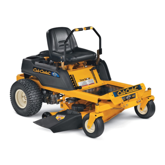
Cub Cadet RZT42 Operator's Manual
Rzt series tractor
Hide thumbs
Also See for RZT42:
- Operator's manual (84 pages) ,
- Specifications (2 pages) ,
- Operator's manual (36 pages)
Table of Contents
Advertisement
Available languages
Available languages
Quick Links
Safe Operation Practices • Set-Up • Operation • Maintenance • Service • Troubleshooting • Warranty
O
'
M
peratOr
s
anual
RZT Series Tractor — Model RZT42
WARNING
READ AND FOLLOW ALL SAFETY RULES AND INSTRUCTIONS IN THIS MANUAL
BEFORE ATTEMPTING TO OPERATE THIS MACHINE.
FAILURE TO COMPLY WITH THESE INSTRUCTIONS MAY RESULT IN PERSONAL INJURY.
CUB CADET LLC, P.O. BOX 361131 CLEVELAND, OHIO 44136-0019
Printed In USA
Form No. 769-06713A
(April 13, 2011)
Advertisement
Chapters
Table of Contents

Related Manuals for Cub Cadet RZT42


Summary of Contents for Cub Cadet RZT42
- Page 1 READ AND FOLLOW ALL SAFETY RULES AND INSTRUCTIONS IN THIS MANUAL BEFORE ATTEMPTING TO OPERATE THIS MACHINE. FAILURE TO COMPLY WITH THESE INSTRUCTIONS MAY RESULT IN PERSONAL INJURY. CUB CADET LLC, P.O. BOX 361131 CLEVELAND, OHIO 44136-0019 Printed In USA Form No. 769-06713A...
-
Page 2: Table Of Contents
Choose from the options below: ◊ Visit us on the web at www.cubcadet.com ◊ Locate your nearest Cub Cadet Dealer at (877) 282-8684 ◊ Write us at Cub Cadet LLC • P.O. Box 361131 • Cleveland, OH • 44136-0019... -
Page 3: Safe Operation Practices
Important Safe Operation Practices WARNING! This symbol points out important safety instructions which, if not followed, could endanger the personal safety and/or property of yourself and others. Read and follow all instructions in this manual before attempting to operate this machine. Failure to comply with these instructions may result in personal injury. - Page 4 A missing or damaged discharge cover can cause blade If situations occur which are not covered in this manual, use contact or thrown object injuries. care and good judgment. Contact your customer service representative for assistance. Stop the blade(s) when crossing gravel drives, walks, or roads and while not cutting grass.
- Page 5 Children Use only an approved gasoline container. Tragic accidents can occur if the operator is not alert to the Never fill containers inside a vehicle or on a truck or trailer bed with a plastic liner. Always place presence of children. Children are often attracted to the machine and the mowing activity.
- Page 6 Do not modify engine Check the blade(s) and engine mounting bolts at frequent intervals for proper tightness. Also, visually inspect blade(s) To avoid serious injury or death, do not modify engine in any for damage (e.g., excessive wear, bent, cracked). Replace way.
-
Page 7: Safety Symbols
Safety Symbols This page depicts and describes safety symbols that may appear on this product. Read, understand, and follow all instructions on the machine before attempting to assemble and operate. Symbol Description READ THE OPERATOR’S MANUAL(S) Read, understand, and follow all instructions in the manual(s) before attempting to assemble and operate WARNING—... - Page 8 2 — s ectiOn peratiOn ractices...
-
Page 9: Assembly & Set-Up
Assembly & Set-Up Contents of Crate • One Lawn Tractor • One Oil Drain Tube • One Deck Wash Hose Coupler • One RZT Operator’s Manual • One Engine Operator’s Manual • One Chute w/ Keys attached Tractor Preparation Lower Deck Discharge Chute Deflector WARNING! Never operate the mower deck without Remove the upper crating material from the shipping pallet, and... - Page 10 Install the discharge chute deflector using the carriage Rotate the seat into position and secure the seat into place bolts, push nuts and flange lock nuts as shown in Fig. 3-3 with the previously removed shoulder bolts and lock nuts. and securely tighten the hardware.
- Page 11 Slide the flat washer onto the hex screw. From the outside, Position the red rubber boot over the positive battery insert the hex screw with washer through the control lever terminal to help protect it from corrosion. slot and the hole of the pivot bracket. Secure with the NOTE: If the battery is put into service after the date shown flange lock nut.
-
Page 12: Controls & Features
Controls & Features Deck Lift Deck Height Handle Index Parking Brake Throttle/Choke Control PTO Switch LH Drive RH Drive Ignition Switch Hour Meter/ Control Lever Control Lever Indicator Panel Seat Adjustment Lever Cup Holder Fuel Tank Cap Storage Tray Figure 4-1 RH and LH Drive Control Levers NOTE: References to LEFT, RIGHT, FRONT, and REAR indicate that position on the tractor when facing forward while seated in the... -
Page 13: Ignition Switch
Ignition Switch Fuel Tank Cap The ignition switch is located on the RH console The fuel tank cap is located near the middle of the LH console. to the right of the operator’s seat. The ignition Turn the fill cap approximately 1⁄4 turn and pull upward to switch has three positions. - Page 14 Cub Cadet dealer. NOTE: If the LH and RH drive control levers are not fully Oil Pressure Indicator (If Engine So Equipped) opened out in the neutral position when engaging the This warning lamp indicates low engine oil pressure.
-
Page 15: Operation
Contact your authorized • Avoid operation on traction surfaces that are unstable; use Cub Cadet Dealer. extreme caution if the surface is slippery. • The safety interlock system prevents the engine from •... -
Page 16: Starting The Engine
• The safety interlock system will shut off the engine if the Turn the ignition key clockwise to the “START” position operator leaves the seat with the PTO engaged, regardless and release it as soon as the engine starts; however, do not of whether the parking brake is engaged. -
Page 17: Driving The Tractor
Stopping the Engine Move the RH and LH drive control levers inward in the neutral position. Refer to Figure 5-2. Place the PTO switch in the “OFF” position. Move the RH and LH drive control levers fully outward in the neutral position. Engage the parking brake. - Page 18 Driving the Tractor Forward To turn to the left, move the left drive control lever rearward of the right lever. See Fig. 5-4. WARNING! Keep all movement of the drive control levers slow and smooth. Abrupt movement of the control levers can affect the stability of the tractor and could cause the tractor to flip over, which may result in serious injury or death to the operator.
- Page 19 Driving the Tractor In Reverse Turning While Driving Rearward WARNING! To turn the tractor while driving rearward, move the control Always look behind and down on both levers as necessary so that one lever is forward of the other. The sides of the tractor before backing up.
- Page 20 Executing a Zero Turn Stopping the Tractor WARNING! Move both drive control levers to the neutral position to When executing a zero turn, the tractor stop the motion of the tractor. MUST BE STOPPED. Executing a zero turn while the tractor is moving can significantly reduce your Push the PTO switch downward to the disengaged control of the tractor and will cause severe turf...
- Page 21 If a safety circuit is not working as designed, free of debris, sticks, stones, wire or other objects contact you Cub Cadet dealer to have the tractor inspected. DO that can be thrown by the rotating blades. NOT operate the tractor if any safety circuit is not functioning properly.
-
Page 22: Maintenance & Adjustment
Warranty repairs must be performed by a Cub Cadet Dealer. Hydrostatic Transmission Dipstick... - Page 23 General Battery Information Using the Deck Wash System WARNING! WARNING! When using the deck wash system, never engage the deck from any position other than • Should battery acid accidentally splatter into the operator’s seat of the tractor. Do not use an the eyes or onto the skin, rinse the affected area assistant or engage deck in the presence of any immediately with clean cold water.
- Page 24 Using the Transmission Bypass Rods Battery Storage If for any reason the tractor will not drive or you wish to move the • When storing the tractor for extended periods, disconnect tractor, the two hydrostatic transmissions are equipped with a the negative battery cable.
-
Page 25: Pivot Bracket
Empty the fuel system: While supporting the control lever to keep it from falling, remove the hex insert flange lock nut and shoulder screw • Prior to putting the tractor in storage, monitor from the bottom of the control lever and pivot bracket. fuel consumption with the goal of running Refer to Fig. - Page 26 Front to Back Leveling Leveling the Mower Deck The front of the deck should be approximately 1⁄4” lower than the When correctly adjusted the mower deck should be level side to rear of the deck. Adjust if necessary as follows: side, and the front of the deck should be approximately 1⁄4 inch lower than the rear of deck.
- Page 27 Adjusting the Gauge Wheels WARNING! Keep hands and feet away from the discharge opening of the cutting deck. NOTE: The deck gauge wheels are an anti-scalp feature of the deck and are not designed to support the weight of the cutting deck.
-
Page 28: Service
Trim Strip If you have a recurring problem with blown fuses, have the tractor’s electrical system checked by your Cub Cadet Service Dealer. Relays and Switches There are several safety switches in the electrical system. If a... - Page 29 Working from the middle of the tractor, pivot the idler While still holding the belt downward, continue turning the bracket and movable idler pulley rearward away from the PTO pulley until the belt is rolled off the pulley. Refer to Fig. 7-4. backside of the ‘V”...
- Page 30 Deck Installation Pull the right side of the belt rearward and place the narrow V side of the belt into the PTO pulley. See Fig. 7-4. To install the mower deck, proceed as follows: While holding the belt and pulley together, rotate the While holding the deck front hanger rod upward, carefully pulley to the left (See Fig.
- Page 31 Use a 15⁄16” wrench to hold the hex nut on top of the spindle Using the ratchet for leverage, pivot the idler bracket and assembly when loosening the hex nut securing the blade. idler pulley away from the backside of the ‘V” belt; then lift A block of wood may be placed between the deck housing the belt off and above the engine pulley and off the idler and the cutting edge of the blade to help in breaking loose...
- Page 32 Remove the flange lock nut and hex screw securing the Loosen the jam nut on the stop bolt, then turn the stop transmission control rod to the transmission control arm. bolt counterclockwise to make it longer. Recheck the Wheel rotation should stop. If it does not, contact your Cub tracking and fine tune the adjustment as necessary.
-
Page 33: Troubleshooting
Troubleshooting Problem Cause Remedy Engine Idles rough Spark plug(s) fouled, faulty or gap too wide. Replace spark plug(s). Set plug gap. Dirty air cleaner. Replace air cleaner element and/or clean pre-cleaner. Excessive vibration Cutting blade loose or unbalanced. Tighten blade and spindle. Damaged or bent cutting blade. -
Page 34: Replacement Parts
Replacement Parts Component Part Number and Description KH-32-883-03-S1 Air Filter w/ Pre-Cleaner KH-12-050-01-S Oil Filter KH-25-050-22-S1 Fuel Filter 759-3336 Spark Plug (RC12YC) 954-04137A Drive Belt (Mowing Deck) 954-04043A Drive Belt (Transmission) 734-04155 Deck Wheel 951-3124E Gas Cap 751-12193* Gas Cap (EPA Phase III) *For use on tractors built after January 1, 2011 in compliance with EPA Phase III Provisions. - Page 35 Component Part Number and Description 925-1707D Battery 746-04539 Throttle/Choke Control Cable 925-1745A Ignition Key 742-04308 Deck Blade 618-04822A Deck Spindle 631-04344 Discharge Chute Assembly 634-04293 Wheel Assembly 634-04212B Caster Wheel Assembly Phone (800) 965-4CUB to order replacement parts or a complete Parts Manual (have your full model number and serial number ready).
-
Page 36: Attachments & Accessories
Attachments & Accessories The following attachments and accessories are compatible with your Cub Cadet RZT tractor. See your Cub Cadet dealer or the retailer from which you purchased your tractor for information regarding price and availability. Part Number Part 19A70020100... - Page 37 Notes...
-
Page 38: Warranties
FEDERAL and/or CALIFORNIA EMISSION CONTROL WARRANTY STATEMENT YOUR WARRANTY RIGHTS AND OBLIGATIONS MTD Consumer Group Inc, the United States Environmental Protection Agency (EPA), and, for those products certified for sale in the state of California, the California Air Resources Board (CARB) are pleased to explain the emission (evaporative and/or exhaust) control system (ECS) warranty on your outdoor 2006 and later small off-road spark-ignited engine and equipment (outdoor equipment engine) In California, new outdoor equipment engines must be designed, built and equipped to meet the State’s stringent anti-smog standards (in other states, 1997 and later model year equipment must be designed, built, and equipped to meet the U.S. - Page 39 WARRANTED PARTS: The repair or replacement of any warranted part otherwise eligible for warranty coverage may be excluded from such warranty coverage if MTD Consumer Group Inc demonstrates that the outdoor equipment engine has been abused, neglected, or improperly maintained, and that such abuse, neglect, or improper mainte- nance was the direct cause of the need for repair or replacement of the part.
- Page 40 Without limiting the foregoing, this limited warranty does not provide coverage in the following cases: The limited warranty set forth below is given by Cub Cadet LLC with respect to new merchandise purchased or leased and used in the a. Routine maintenance items such as lubricants, filters, blade...
- Page 41 LEA Y RESPETE TODAS LAS NORMAS DE SEGURIDAD E INSTRUCCIONES INCLUIDAS EN ESTE MANUAL ANTES DE PONER EN FUNCIONAMIENTO ESTA MÁQUINA. SI NO RESPETA ESTAS INSTRUCCIONES PUEDE PROVOCAR LESIONES PERSONALES. CUB CADET LLC, P.O. BOX 361131 CLEVELAND, OHIO 44136-0019 Impreso en Estados Unidos de América Formulario No. 769-06713A...
- Page 42 Elija entre las opciones que se presentan a continuación: ◊ Visite nuestro sitio web en www.cubcadet.com ◊ Llame a un representante de Asistencia al Cliente al (800) 965-4CUB ◊ Escríbanos a Cub Cadet LLC • P.O. Box 361131 • Cleveland, OH • 44136-0019...
-
Page 43: Medidas Importantes De Seguridad
Medidas importantes de seguridad ADVERTENCIA: La presencia de este símbolo indica que se trata de instrucciones importantes de seguridad que se deben respetar para evitar poner en peligro su seguridad personal y/o material y la de otras personas. Lea y siga todas las instrucciones de este manual antes de poner en funcionamiento esta máquina. - Page 44 Esté atento a la cortadora y a la dirección de la descarga de Desenganche todos los embragues de los accesorios, los aditamentos y no apunte a nadie. Nunca haga funcionar coloque el freno de mano en posición ‘on’ y mueva las la cortadora de césped sin que estén colocados la cubierta palancas de control de transmisión totalmente hacia afuera de descarga o todo el colector de recortes de césped.
- Page 45 Haga que todos los movimientos en las pendientes sean No permita nunca que los niños menores de 14 años lentos y graduales. No cambie repentinamente la velocidad utilicen esta máquina. Los niños de 14 años en adelante ni la dirección. La aceleración o la reducción repentina deben leer y entender las instrucciones de operación y de velocidad puede hacer que el frente de la máquina normas de seguridad contenidas en este manual, y en la...
- Page 46 Llene el tanque no más de ½ pulgada por debajo Nunca modifique el sistema de bloqueo de seguridad ni de la base del cuello del tapón de carga, para dejar otros mecanismos de seguridad. Controle periódicamente espacio para la expansión del combustible. que funcionen correctamente.
- Page 47 Amortiguador de chispas Si se utiliza un amortiguador de chispas el operador lo debe mantener en condiciones de uso adecuadas. En el Estado ADVERTENCIA: Esta máquina está equipada con un de California las medidas anteriormente mencionadas son motor de combustión interno y no debe ser utilizada exigidas por ley (Artículo 4442 del Código de Recursos Públicos en o cerca de un terreno agreste cubierto por bosque, de California).
- Page 48 2 — M ección edidas de seguridad...
-
Page 49: Montaje Y Configuración
Montaje y Configuración Contenido del cajón • Un tractor corta césped • Un tubo de drenaje de aceite • Un acoplador de manguera para lavado de plataforma • Un Manual del operador del RZT • Un Manual del operador del motor •... - Page 50 Instale el deflector del canal de descarga con los pernos Gire el asiento en su posición y asegure el asiento en su del carro, empuje las tuercas y la brida de tuercas como se lugar con los pernos de reborde y tuercas de fijación que muestra en la figura.
- Page 51 Deslice la arandela plana hacia el tornillo hexagonal. Retire la cubierta de plástico, si está presente, a partir de la Desde afuera, inserte el tornillo hexagonal con arandela negativa terminal de la batería y conectar el cable negro a través de la ranura de la palanca de control y el orificio a la terminal de la batería negativo (-) con el tornillo y la del soporte de pivote.
-
Page 52: Controles Y Características
Controles y Características Manija de Posicionamiento elevación de de la altura de la la plataforma plataforma Freno de mano Del acelerador y del estrangulador Interruptor de potencia de arranque Interruptor Palanca de Palanca de Medidor horario/ de encendido control de control de Panel indicador transmisión... - Page 53 Interruptor de encendido Tapón del tanque de combustible El interruptor de encendido está ubicado El tapón del depósito de combustible está ubicado cerca de en la consola del lado derecho, a la derecha la parte media de la consola del lado izquierdo. Gire el tapón del asiento del operador.
- Page 54 Póngase en • Después de arrancar y calentar el motor, mueva la manija contacto con el distribuidor Cub Cadet para que se realice la de control hacia atrás hasta que sienta que pasa el inspección del tractor y del motor.
-
Page 55: Funcionamiento
Si el sistema de bloqueo al arrancar y detenerse. Sujete bien las palancas de control. funciona mal, no se debe hacer funcionar el tractor. Póngase en contacto con su distribuidor autorizado Cub Cadet. • Sea cuidadoso al operar cerca de rutas. Detenga el movimiento del tractor y espere a que pasen los vehículos... - Page 56 No opere el tractor si detenga el motor inmediatamente. Haga controlar el alguna parte del sistema de bloqueo funciona tractor por el distribuidor Cub Cadet. mal. Controle periódicamente las funciones del Arranque del motor en clima frío sistema de bloqueo para verificar que funcionen adecuadamente.
- Page 57 Detención del motor Coloque las palancas de control de transmisión del lado derecho y del lado izquierdo hacia adentro, en posición Coloque el interruptor de la potencia de arranque (PTO) en neutral. Vea la Figura 5-2. posición "OFF" (apagado). Coloque las palancas de control de transmisión del lado derecho y del lado izquierdo totalmente hacia afuera, en posición neutral.
- Page 58 Conducción del tractor hacia adelante Para girar a la izquierda, mueva la palanca de control del lado izquierdo hacia atrás respecto de la palanca derecha. ¡ADVERTENCIA! Todos los movimientos de las Vea la Fig. 5-4. palancas de control deben ser lentos y suaves. El movimiento abrupto de las palancas de control puede afectar la estabilidad del tractor y podría hacer que el tractor se voltee, con el resultado de...
- Page 59 Conducción del tractor en marcha atrás Realizar un giro mientras se conduce marcha atrás ¡ADVERTENCIA! Para que el tractor gire mientras se desplaza hacia atrás, mueva Siempre mire hacia atrás y hacia las palancas de control según sea necesario para que una abajo a ambos lados del tractor antes de desplazarse palanca quede más adelante que la otra.
- Page 60 Giro de radio cero Detención del tractor ¡ADVERTENCIA! Mueva las dos palancas de control a la posición neutral Para realizar un giro de radio para detener el movimiento del tractor. cero, el tractor SE DEBE DETENER. La realización de un giro de radio cero con el tractor en movimiento Presione el interruptor de la potencia de arranque (PTO) puede reducir significativamente el grado de control hacia abajo a la posición desenganchada.
- Page 61 Cub Cadet para que inspeccione el las cuchillas rotativas. tractor. NO use el tractor si algún circuito de seguridad no está...
-
Page 62: Mantenimiento Y Ajustes
Mantenimiento y Ajustes Calendario de mantenimiento Antes de Cada Cada Cada Cada Antes de Cada uso 10 horas 25 horas 50 horas 100 horas almacenar Inspeccione la pantalla/cubierta de entrada del motor Limpie los bornes de la batería Lubrique el eje de pivote delantero y los ejes de las rueditas Limpie las aletas de refrigeración del motor Lubrique las ruedas de la plataforma Mantenimiento... - Page 63 Información general sobre la batería Uso del sistema de lavado de la plataforma ¡ADVERTENCIA! ¡ADVERTENCIA! Cuando use el sistema de lavado de la plataforma, nunca enganche la plataforma • En caso de que se produzca una salpicadura desde otra posición que no sea la del asiento del accidental de ácido en los ojos o la piel, enjuague operador del tractor.
- Page 64 Uso de las varillas de derivación de la transmisión Almacenamiento de la batería Si por alguna razón el tractor no funciona o usted desea moverlo, • Cuando el tractor se guarda durante períodos prolongados, las dos transmisiones hidrostáticas están equipadas con una desconecte el cable negativo de la batería.
- Page 65 Vaciado del sistema de combustible: Mientras sostiene la palanca de control para evitar que caiga, quite la tuerca de seguridad con brida de bulón • Antes de guardar el tractor, observe el hexagonal y el tornillo con reborde de la base de la palanca consumo de combustible a los efectos de control y soporte de pivote.
- Page 66 Nivelación de adelante hacia atrás Nivelación de la plataforma de la cortadora de césped La parte frontal de la plataforma debe ser de aproximadamente Cuando se encuentra correctamente ajustada, la plataforma de 1 / 4 de pulgada más bajo que la parte trasera de la cubierta. la cortadora de césped debe estar nivelada de lado a lado, y la Ajustar si es necesario lo siguiente: parte delantera de la plataforma debe estar aproximadamente 1⁄4...
- Page 67 Ajuste de las ruedas de calibración ¡ADVERTENCIA! Mantenga las manos y pies alejados de la abertura de descarga de la plataforma de corte. NOTA: Las ruedas calibradoras de la plataforma constituyen un mecanismo para el cuidado del césped y no fueron diseñadas para soportar el peso de la plataforma de corte.
-
Page 68: Servicio
Servicio Retiro de la batería Carga de la batería ¡ADVERTENCIA! Si el tractor ha estado guardado durante un tiempo, pruebe la Los postes, bornes y accesorios batería y, si es necesario, recárguela. de la batería contienen plomo y compuestos de plomo. - Page 69 Para aflojar la tensión de la correa con la polea loca. Mientras sostiene la correa hacia abajo, siga girando la polea de la potencia de arranque (PTO) hasta que la correa Usando la manija de elevación de la plataforma, levante se deslice fuera de la polea.
- Page 70 Deslice la plataforma hacia adelante de modo que la varilla de Oriente el lado trasero de la correa alrededor de la polea suspensión delantera de la plataforma se pueda levantar fuera loca fija de la plataforma. Consulte la Fig. 7-3. de las dos ranuras del soporte delantero de la plataforma.
- Page 71 Instale la nueva correa alrededor de las poleas del husillo Cuando reinstale las cuchillas, asegúrese de que se instalen tal como se muestra en la Figura 7-6 y vuelva a instalar las de modo que las aletas de ventilación se orienten hacia cubiertas de la correa.
- Page 72 Si no hace, entrar en contacto con a su para alargarlo. Vuelva a controlar la desviación y retoque el distribuidor autorizado del servicio del Cub Cadet. ajuste según sea necesario. Si la rotación para, ajuste la barra de control hacia arriba...
-
Page 73: Solución De Problemas
Solución de Problemas Problema Causa Solución Vibración excesiva Cuchilla de corte floja o descentrada. Apriete la cuchilla y el husillo. Cuchilla dañada o curvada. Reemplace la cuchilla. Corte desigual La plataforma no está correctamente Haga un ajuste de la plataforma de lado a nivelada. -
Page 74: Garantías
DECLARACIÓN FEDERAL y/o DE CALIFORNIA SOBRE GARANTÍAS EN EL CONTROL DE EMISIONES SUS DERECHOS Y OBLIGACIONES EN CUANTO A LA GARANTÍA MTD Consumer Group Inc, la Agencia de Protección Medioambiental de los Estados Unidos (EPA), y para aquellos productos certificados para su venta en el es- tado de California, el Departamento de los Recursos del Aire de California (CARB) se complacen en explicar la garantía que cubre al sistema de control (ECS) de emisiones (evaporativas y/o de escape) de su equipo y motor (motor de equipos de exteriores) de encendido por chispa para todo terreno, pequeño, de exteriores del año 2006 y años posteriores En California, los nuevos motores de equipos de exteriores deben estar diseñados, construidos y equipados para cumplir con las... - Page 75 Durante la totalidad del período de garantía del motor y equipo para todo terreno arriba mencionado, MTD Consumer Group Inc mantendrá un suministro de piezas bajo garantía suficiente para satisfacer la demanda esperada de tales piezas. Cualquier pieza de reemplazo se podrá usar para el cumplimiento del mantenimiento o las reparaciones bajo garantía y se suministrarán sin cargo para el propietario.
- Page 76 El daño resultante de la instalación o el uso de piezas, accesorios En ningún caso se obtendrá una compensación mayor al monto o complementos no aprobados por Cub Cadet para su uso con el o del precio de compra del producto vendido. La modificación de las los productos incluido(s) en este manual anulará...
Need help?
Do you have a question about the RZT42 and is the answer not in the manual?
Questions and answers