
Related Manuals for pro-drive shallow water outboard

Summary of Contents for pro-drive shallow water outboard
- Page 1 OWNERS MANUAL www.prodriveoutboards.com PO Box 949 PH#: 337- 229-0034 129 S Main St. FAX#: 337- 229-2302 Loreauville, LA 70552...
-
Page 2: Table Of Contents
TO THE OWNER Thank you for purchasing a “Pro-Drive Shallow Water Outboard”. Your unit is designed for long life,dependability, ease of operation, safety, and top performance that you deserve and expect. Take time now to read this manual and the safety precautions. -
Page 3: Safety Instructions
Safety Instructions IMPORTANT Read and understand these instructions. They are for your safety. Failure to follow these instructions may result in porperty damage, personal injury, or death. • Read and understand engine manufacturer’s owners manual. Attach safety kill switch lanyard to you before starting the engine. •... -
Page 4: Installation Instructions
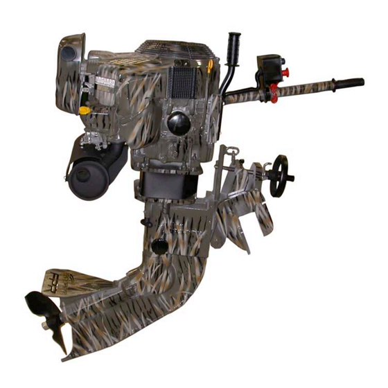
Installation Instructions After installing your motor on the boat transom use the aluminum transom saver plate supplied with the unit, torque the boats to 25 ft. Lbs. Of torque. Located on the back of the transom bracket there are three sets of holes on each side. Drill a 7/16” hole through the transom. - Page 5 Unit Component And Control Feature Identification Engine Tilt Control Handle Twist Grip Throttle Tiller Handle Tower Trim Wheel Housing Friction Screw Trim Wheel Cavitation Plate Lower Unit Transom Bracket Prop Your PD# Is Skeg Plate Located Here...
- Page 6 Identifing The Controls And Control Box Iginition Switch Momentary Engagement Button (Off / Clockwise On) Push In (Forward) Continue Clockwise Engages Starter Release (Neutral) Safety Kill Clutch Switch Choke Switch Push In (Neutral) Pull Out (Engaged) Pull Out (Forward) Push In (Disengage)
-
Page 7: Start Up
START UP *Note: your engine is shipped without oil. Oil must be added before starting your engine. See the engine manual. (Check before adding oil. Do not overfill) • Visually check unit for any loose, damaged or missing parts. • Attach safety lanyard if electing to do so. -
Page 8: Operation Instructions
Operation Instructions Regular Operation • Make sure engine ignition is off. • Check engine oil. • Attach safety kill switch. (If electing to do so.) • Make sure clutch button is pushed in ensuring it is in neutral. (Note: Engine will not start while the clutch button is pulled out.) •... -
Page 9: Reverse Procedure
Running In Grass, Hydrilla & Lillies With Water Underneath • While your boat is on step and running, no trim wheel adjustment is needed. • Under extremely heavy conditions, you may need to trim down slightly, and clear the prop by rasing the engine while getting on step. (Clearing the prop may need to be done more than once in heavy vegetation while getting on step.) Once on step, trim to normal running position. - Page 10 The concept is explained by comparing it to the same way a common ratchet and socket set in your tool set works. Below are some diagrams with explanations on how this system works. First, you will have to adjust your friction knob by tightening it. This just like when tightening a nut and bolt with a ratchet, some friction is needed to make the ratchet mechanism work, Step 1.
- Page 11 Step 2. Pull the reverse release pin down. Pull the tiller toward you slightly, then release the pin and continue pulling the tiller toward you until you here the unit click. (Once you release the pin you will not have to pull the pin again until you are ready to go back into the forward position.) Push the tiller handle away from you again like in step 1 and repeat.
- Page 12 This picture shows the release lever lock for units with hydraulic power trim in the unlock position. Step 3. Once the unit is in reverse, lock the trim down with the lever loc. *Note: the reverse lever must not be locked when running in forward gear. Repeat the above procedure to return to forward gear.
- Page 13 Manual Reverse Locking Block This picture shows the reverse locking block for a manual trim unit, in the unlock position. This picture shows the reverse locking block in the lock position. Important While in reverse in deep water, (anything over 10 inches), reverse gear should only be used at idle speeds.
-
Page 14: Unit Maintenance
Unit Maintenance • Lower unit oil should be checked every 25 hours or once a month. Use only SAE 80W-90 gear lubricant API service GL-5 (A synthetic gear oil such as Royal Purple may be used.) Lower unit oil should be replaced once a year or every 50 hours. (See •... - Page 15 Important Added maintance procedure for 2008 model lower units Your unit is already serviced new. This is for after 25 hours. Long Shank Short Shank Remove pipe plug Remove pipe plug using 3/8” allen using 3/8” allen wrench wrench With mo tor turn ed completely straight locate grease fitting.
- Page 16 The diagram below shows the tower housing sleeve grease fittings. Pump two to three shots of grease here at 25 hours. GREASE PORT GREASE PORT The diagram below shows the grease ports of the reverse assembly. These needs to be greased every 25 hours or once a year. Pump two shots of grease into each.
- Page 17 Grease tower housing pivot pin every 25 hours or once a season (located behind the trim wheel) Grease thrust bearing on trim wheel once a year. Salt Water Applications • After returning from trip wash complete unit with fresh water and allow to dry. Run engine.
- Page 18 DIAGRAM B – REPLACING OIL (Once a Year or every 50 hours) *NOTE: IF YOUR OIL IS CLEAR AND NOT CONTAMINATED AT THE INSPECTION OR DRAIN PORT, OIL DOES NOT NEED TO BE CHANGED. STEP #1 REMOVE BOTTOM PLUG USING A 1/4” ALLEN WRENCH. REMOVE TOP PLUGS AS INDICATED IN DIAGRAM A.
-
Page 19: Propeller Removal
Propeller Removal *Note: Do not engage the clutch to remove the prop. Doing so may damage the clutch and void clutch warranty. Always disconnect to battery before attempting to remove the Propeller or any other work or service on your unit. Hole Stop Remove the clutch cover wrap and locate the hole stop as shown on left. - Page 20 Removing The Prop Taper Bushing In most cases when the prop is removed the taper bushing will remain in the prop. To remove the bushing use vise grip pliers or channel locks as shown below to compress the bushing and twist slightly Propeller Re-Installation Using locktite marine grade ant-seize or never seize coat the entire shaft.
- Page 21 Install the tapered bushing as shown, making sure that it is fully forward and bottoming out at the threads end. Coat the outside diameter of the bushing as in the above step. Install the prop by hand using gloves and tighten thoroughly. It is not necessary to use the wrench for this step.
-
Page 22: Trouble Shooting Tips
*Check ground wire attached under the tiller handle ENGINE WON'T START (clean and retighten it). *If this does not correct the problem, call your authorized dealer or Pro-Drive Outboards. *Make sure your tank is vented. ENGINE LOSING POWER OR STOPPING *Make sure your fuel lines are 1/4". -
Page 23: Limited Warranty
Please take a few minutes to read this Limited Warranty Guide in its entirety. It contains the information you will need to have your Pro-Drive repaired in the unlikely event that a failure should occur. PLEASE NOTE: It is the customer’s responsibility to familiarize him/herself with the limited warranty guide. - Page 24 Pro-Drive dealer. However, the dealer’s own customers may have priority. Right To Make Changes Pro-Drive reserves the right to make any changes to a Pro-Drive product at any time without incurring any obligation with respect to any product previously ordered, sold, or shipped.
Need help?
Do you have a question about the shallow water outboard and is the answer not in the manual?
Questions and answers