
Related Manuals for Delta Sidekick 36-210


Summary of Contents for Delta Sidekick 36-210
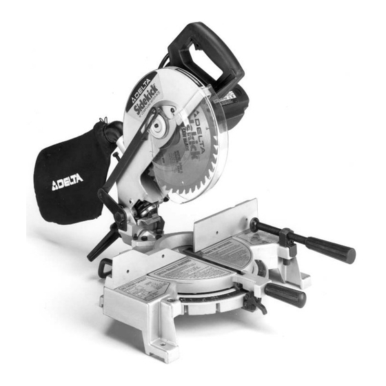
- Page 1 Sidekick 10" Compound Miter Box (Model 36-210 beginning with serial no. K9611 PART NO. 1349945 DATED 4-1-96 © Delta International Machinery Corp. 1996...
-
Page 2: Table Of Contents
Delta Building Trades and Home Shop MachineryTwo Year Limited Warranty Delta will repair or replace, at its expense and at its option, any Delta machine, machine part, or machine accessory which in normal use has proven to be defective in workman-... -
Page 3: Safety Rules
If a procedure feels dangerous, don’t try it. Figure out an alternative procedure that feels safer. REMEMBER: Your personal safety is your responsibility. This machine was designed for certain applications only. Delta Machinery strong- ly recommends that this machine not be modified and/or used for any application other than that for which it was designed. -
Page 4: Additional Safety Rules For Compound Miter Boxes
32. THE USE of attachments and accessories not rec- 12. NEVER use blades larger or smaller in diameter than ommended by Delta may result in the risk of injuries. ten inches. 33. SHOULD any part of your miter box be missing, 13. -
Page 5: Unpacking
UNPACKING 1. Remove the miter box and all loose items from the carton. IMPORTANT: DO NOT LIFT THE MITER BOX BY THE SWITCH HANDLE OR TABLE CONTROL HANDLE AS THIS MAY CAUSE MISALIGNMENT. ALWAYS LIFT THE MACHINE BY THE BASE. 2. -
Page 6: Rotating Table To The 90 Degree Position
ROTATING TABLE TO THE 90 DEGREE POSITION 1. Loosen table locking handle (A) Fig. 5, one turn and pull back locking trigger (B). Rotate table until plunger (C)is engaged into the 90 degree stop (D). Then tighten handle (A). Fig. 5 ASSEMBLING DUST SPOUT 1. -
Page 7: Fastening Machine To Supporting Surface
Fig. 9 FASTENING MACHINE TO SUPPORTING SURFACE Before operating your compound miter box, make sure it is firmly mounted to a workbench or other supporting surface. Four holes are provided, two of which are shown at (A) Fig. 9, for fastening the saw to a supporting sur- face. -
Page 8: Connecting Saw To Power Source
CONNECTING SAW TO POWER SOURCE POWER CONNECTIONS A separate electrical circuit should be used for your tools. This circuit should not be less than #12 wire and should be protected with a 20 Amp fuse. Have a certified electrician replace or repair a worn cord immediately. Before connect- ing the motor to a power line, make sure the switch is in the “OFF”... -
Page 9: Operating Controls
OPERATING CONTROLS STARTING AND STOPPING MACHINE To start the machine, depress switch trigger (A) Fig. 13. To stop the machine, release the switch trigger. This miter box is equipped with an automatic electric blade brake. As soon as the switch trigger (A) Fig. 13, is released, the electric brake is activated and stops the blade in seconds. -
Page 10: Pointer And Scale
POINTER AND SCALE A pointer (A) Fig. 16, is supplied which indicates the actual angle of cut. Each line on the scale (B) represents 1/2 degree. In effect, when the pointer is moved from one line to the next on the scale, the angle of cut is changed by 1/2 degree. -
Page 11: Rear Support/Carrying Handle
Fig. 19 REAR SUPPORT / CARRYING HANDLE A rear support bar (A) Fig. 19, is provided to prevent the miter box from tipping to the rear when the cuttinghead is returned to the up position after a cut has been made. For maximum support the bar (A) should be pulled out as far as possible. -
Page 12: Adjustments
ADJUSTMENTS ADJUSTING TABLE POSITIVE STOPS 1. Move the table to the 90 degree straight cut-off po- sition, making sure the plunger is engaged in the 90 degree positive stop and tighten the lock handle (A) Fig. 2. Make a cut on a piece of wood, as shown in Fig. 21. Fig. -
Page 13: Adjusting 90 And 45 Degree Bevel Stops
ADJUSTING 90 AND 45 DEGREE BEVEL STOPS 1. DISCONNECT THE SAW FROM THE POWER SOURCE. 2. Loosen bevel lock handle and move the cutting arm all the way to the right, then tighten the bevel lock handle. 3. Using a square (A) Fig. 25, place one end of the square on the table and the other end against the blade. -
Page 14: Changing Handle Position
Fig. 29 Fig. 30 CHANGING HANDLE POSITION The cuttinghead handle (A) Figs. 29 and 30, can be repositioned for operator convenience by loosening the two screws (B) and sliding the handle (A) to the desired position. Then tighten the two screws (B). Fig. -
Page 15: Adjusting Blade Parallel To Table Slot
ADJUSTING BLADE PARALLEL TO TABLE SLOT 1. DISCONNECT THE SAW FROM THE POWER SOURCE. 2. NOTE: This adjustment should be checked with the cutting arm moved all the way to the right (blade 90 degrees to the table) and the table in the 90 degree straight cut-off position (blade 90 degrees to the fence). -
Page 16: Auxiliary Wood Fence
AUXILIARY WOOD FENCE When performing multiple or repetitive cut-off operations that result in small cut-off pieces, one inch or less, it is possible for the saw blade to catch the cut-off pieces and project them out of the machine or into the blade guard and housing, possibly causing damage or injury. -
Page 17: Cutting Aluminum
CUTTING ALUMINUM Aluminum extrusions such as used for making aluminum BLADE screens and storm windows can easily be cut with your FENCE compound miter box. When cutting aluminum extru- sions, or other sections that can be cut with a saw blade and are within the capacity of the machine, position the material so the blade is cutting through the smallest RIGHT... -
Page 18: Cutting Crown Moulding
CUTTING CROWN MOULDING One of the many features of your saw is the ease of cut- ting crown moulding. The following is an example of cut- ting both inside and outside corners on 53/38 degree wall angle crown moulding. NOTE: When cutting 45 degree wall angle crown moulding the following proce- dure for inside and outside corners is the same with the Fig. -
Page 19: Constructing Work Support Extensions
Fig. 46 CONSTRUCTING WORK SUPPORT EXTENSIONS One of the unique features of your miter box is the ease with which you can construct work supports. Fig. 46, illustrates the miter box mounted to two standard 2 x 4’s (A). Fasten the grooves in the four mounting legs, two of which are shown at (B), to the 2 x 4’s using four screws through the four holes in the mounting legs. -
Page 20: Brush Inspection And Replacement
3. Rotate arbor cover (B) Fig. 48, and lower guard (G) to the rear, exposing arbor screw (C), as shown. 4. Remove arbor screw (C) Fig. 48, by turning screw clockwise with wrench supplied while at the same time pressing in on arbor lock (D) Fig. 49, to keep the arbor from turning.
Need help?
Do you have a question about the Sidekick 36-210 and is the answer not in the manual?
Questions and answers