Advertisement
DODGE PLUG IN MODEL 250 POWER SUPPLY
These instructions must be read thoroughly before installing or operating this product.
WARNING: Only qualified electrical personnel familiar with
the construction and operation of this equipment and the
hazards involved should install, adjust, and/or service this
equipment. Failure to observe this precaution can result in
bodily injury.
WARNING: The user is responsible for conforming to the
National Electrical Code and all other applicable local codes
in respect to wiring practices, grounding, disconnects,
and overcurrent protection. Installation of an approved
disconnecting means in the line side of the controller is of
particular importance. Failure to observe these precautions
could result in severe bodily injury or loss of life.
WARNING: Subsequent steps require rotating parts and/or
electrical circuits to be exposed. Stay clear if unit must be
running or disconnect and lockout or tag power source if
contact must be made. Failure to observe these precautions
could result in severe bodily injury or loss of life.
WARNING: Because of the possible danger to persons(s) or
property from accidents which may result from the improper
use of products, it is important that correct procedures be
followed. Products must be used in accordance with the
engineering information specified in the catalog. Proper
installation, maintenance and operation procedures must
be observed. The instructions in the instruction manuals
must be followed. Inspections should be made as necessary
to assure safe operation under prevailing conditions. Proper
guards and other suitable safety devices or procedures as
may be desirable or as may be specified in safety codes
should be provided, and are neither provided by Baldor
Electric Company nor are the responsibility of Baldor
Electric Company. This unit and its associated equipment
must be installed, adjusted and maintained by qualified
personnel who are familiar with the construction and
operation of all equipment in the system and the potential
hazards involved. When risk to persons or property may
be involved, a failsafe device must be an inegral part of the
driven equipment beyond the speed reducer output shaft.
INSTALLATION MANUAL FOR
Specifications:
Input voltage: 115 VAC 50-60 Hz
Output voltage: 15-100 VDC Nominal
Output current: 0.5 Amp Maximum
Output wattage: 50 Watts Maximum
Dimensions: 2.88" H, 2.38" W, 1.75" D
Description:
Model 250 is an octal-base power supply that converts 115
VAC, 50-60 Hz to a DC voltage. It provides one fixed 100
VDC output and one adjustable (15 to 100 VDC) output. The
Model 250 is capable of providing DC operating voltage to
1 or 2 clutches or brakes (each with 50 watts or less power
consumption). If two units are operated with the Model 250
power supply, only one unit should be energized at a time.
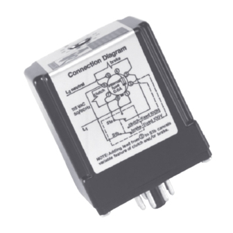
Note: Switches Furnished By User.
Installation and Operating Instructions:
1.
Be sure power is locked off when wiring a power supply
installation.
2.
Use adequate sized wire. No. 18 gauge is recommended
for runs less than 25 feet. No. 16 gauge is recommended
for runs 25 feet or longer.
3.
The neutral or grounded side of the 115 VAC line must be
connected to terminal 5 on the octal socket. A voltmeter
connected between the neutral line and line ground will
read 0 volts. The hot side of the 115 VAC line must be
connected to terminal 1.
Note 1: Connect switches per diagrams. Do not connect
switch for the clutch or brake in coil circuit.
Note 2: Output voltage under load of the power supply is
approximately 100 VDC with 115 VAC input. This is suitable
for clutches and brakes rated 90 VDC.
Note 3: Output voltage without load is about 160 VDC.
Model 250 used with 2 units - adjustable voltage on unit
#1, fixed 100 VDC on unit #2. Connection Instructions (See
Figure 1):
1.
All connections are made to terminals on octal socket.
2.
Connect unit #1 to terminals 6 and 8.
3.
Connect unit #2 to terminals 3 and 6.
4.
Connect side Sa of a double-pole, double-throw (DPDT)
switch to terminals 3, 7, and 8; the switch common must be
connected to terminal 7.
5.
Connect side Sb of the switch to terminals 6 and 2; the
switch common must be connected to terminal 6.
6.
Connect 115 VAC, 50-60 Hz to terminals 1 and 5.
NOTE: The neutral or grounded side must be
connected to terminal 5.
1
Advertisement
Table of Contents

Related Manuals for Dodge 250


Summary of Contents for Dodge 250
-
Page 1: Specifications
90 VDC. Note 3: Output voltage without load is about 160 VDC. Model 250 used with 2 units - adjustable voltage on unit #1, fixed 100 VDC on unit #2. Connection Instructions (See Figure 1):... - Page 2 Connect switch to terminals 7 and 8; the switch common should be connected to terminal 7. Use a maintained Model 250 used with 2 units – adjustable voltage on both contact SPDT (shown in Figure 3) or SPST switch. units.Connection Instructions (See Figure 2): Connect 115 VAC, 50-60 Hz to terminals 1 and 5.
-
Page 3: Troubleshooting
If the above corrective actions do not restore normal operation, the power supply should be replaced with a new Model 250 has an internal fuse. The fuse can be checked one. without removing the power supply cover. First remove the power supply from the octal socket. - Page 4 World Headquarters P.O. Box 2400, Fort Smith, AR 72902-2400 U.S.A., Ph: (1) 479.646.4711, Fax (1) 479.648.5792, International Fax (1) 479.648.5895 Dodge Product Support 6040 Ponders Court, Greenville, SC 29615-4617 U.S.A., Ph: (1) 864.297.4800, Fax: (1) 864.281.2433 www.baldor.com *4008-1110* © Baldor Electric Company All Rights Reserved.
Need help?
Do you have a question about the 250 and is the answer not in the manual?
Questions and answers