
Related Manuals for Thermadyne CutMaster 75

Summary of Contents for Thermadyne CutMaster 75
- Page 1 Plasma Cutting Power Supply CutMaster™ 75 CE CutMaster™ 75 A-02990 Service Manual March 22, 2004 Manual No. 0-2869...
- Page 3 WARNINGS Read and understand this entire Manual and your employer’s safety practices before installing, oper- ating, or servicing the equipment. While the information contained in this Manual represents the Manufacturer's best judgement, the Manufacturer assumes no liability for its use. Plasma Cutting Power Supply CutMaster™...
-
Page 4: Table Of Contents
TABLE OF CONTENTS SECTION 1: GENERAL INFORMATION ....................1-1 1.01 Notes, Cautions and Warnings ..............1-1 1.02 Important Safety Precautions ............... 1-1 1.03 Publications ....................1-2 1.04 Note, Attention et Avertissement ..............1-3 1.05 Precautions De Securite Importantes ............1-3 1.06 Documents De Reference ................ - Page 5 TABLE OF CONTENTS (continued) SECTION 6: PARTS LISTS ........................6-1 6.01 Introduction ....................6-1 6.02 Ordering Information ..................6-1 6.03 Major External Replacement Parts ............... 6-2 6.04 Front Panel Replacement Parts ..............6-3 6.05 Left Side Internal Replacement Parts ............6-4 6.06 Rear Panel Replacement Parts ..............
-
Page 7: General Information
SECTION 1: GASES AND FUMES GENERAL INFORMATION Gases and fumes produced during the plasma cutting process can be dangerous and hazardous to your health. 1.01 Notes, Cautions and Warnings • Keep all fumes and gases from the breathing area. Throughout this manual, notes, cautions, and warnings Keep your head out of the welding fume plume. -
Page 8: Publications
• Wear dry gloves and clothing. Insulate yourself from the work piece or other parts of the welding PLASMA ARC RAYS circuit. • Repair or replace all worn or damaged parts. Plasma Arc Rays can injure your eyes and burn your skin. •... -
Page 9: Note, Attention Et Avertissement
6. ANSI Standard Z49.2, FIRE PREVENTION IN THE USE ATTENTION OF CUTTING AND WELDING PROCESSES, obtain- able from American National Standards Institute, 1430 Broadway, New York, NY 10018 Toute procédure pouvant résulter l’endommagement du matériel en cas de non- 7. AWS Standard A6.0, WELDING AND CUTTING CON- respect de la procédure en question. - Page 10 • Eloignez toute fumée et gaz de votre zone de respira- • Ne touchez jamais une pièce “sous tension” ou “vive”; tion. Gardez votre tête hors de la plume de fumée portez des gants et des vêtements secs. Isolez-vous provenant du chalumeau. de la pièce de travail ou des autres parties du circuit de soudage.
-
Page 11: Documents De Reference
ultra-violets très forts. Ces rayons d’arc nuiront à vos 1.06 Documents De Reference yeux et brûleront votre peau si vous ne vous protégez pas correctement. Consultez les normes suivantes ou les révisions les plus récentes ayant été faites à celles-ci pour de plus amples •... - Page 12 9. Norme 70 de la NFPA, CODE ELECTRIQUE NA- TIONAL, disponible auprès de la National Fire Pro- tection Association, Batterymarch Park, Quincy, MA 02269 10. Norme 51B de la NFPA, LES PROCÉDÉS DE COUPE ET DE SOUDAGE, disponible auprès de la National Fire Protection Association, Batterymarch Park, Quincy, MA 02269 11.
-
Page 13: Declaration Of Conformity
Thermal Dynamics has been manufacturing products for more than 30 years, and will continue to achieve excellence in our area of manufacture. Manufacturers responsible representative: Steve Ward Operations Director Thermadyne Europe Europa Building Chorley N Industrial Park Chorley, Lancashire, England PR6 7BX... -
Page 14: Statement Of Warranty
1.08 Statement of Warranty LIMITED WARRANTY: Thermal Dynamics ® Corporation (hereinafter “Thermal”) warrants that its products will be free of defects in workmanship or material. Should any failure to conform to this warranty appear within the time period applicable to the Thermal products as stated below, Thermal shall, upon notification thereof and substantiation that the product has been stored, installed, operated, and maintained in accordance with Thermal’s specifications, instructions, recommendations and recognized standard industry practice, and not subject to misuse, repair, neglect, alteration, or accident, correct such defects by suitable repair or replacement, at Thermal’s sole option,... -
Page 15: Introduction
This manual provides service instructions for the Ther- Maintenance work should be accomplished in a timely mal Dynamics CutMaster 75 Plasma Cutting Power Sup- manner. If problems are encountered, or the equip- ply. Information in this manual is particularly applicable... - Page 16 INTRODUCTION Manual 0-2869...
-
Page 17: Description
• Gas Pressure Regulator/Filter Assembly tomer operating personnel. • Gas Supply Connection 3.02 General Description • Grounding Stud (CE Cutmaster 75 only) 4. Input Power* The power supply provides 60 amp maximum output and includes all control circuitry, electrical and gas inputs and •... -
Page 18: Power Supply Options And Accessories
7. Pilot Circuitry C. Extended Work Cable with Clamp Capacitive Discharge (CD), Ignition DC Pilot As an alternative to the standard 20 ft (6.1 m) work cable & clamp factory installed on the power supply, 8. Weight an optional 50 ft (15.2 m) work cable with clamp is available. -
Page 19: Service Troubleshooting Diagnostics
Indicator Meaning 4.03 System Theory CD on Inverter on The CutMaster 75 System is designed for hand operation Torch Switch On and mechanized operation using the torch control bulk- Drag Circuit on head within the power supply as the interface. -
Page 20: Common Operating Problems
B. CD (Capacitive Discharge) Board Functions D. Direction of Cut The CD Board functions are initiated by the CD En- The plasma gas stream swirls as it leaves the torch. able signal from the Logic PC Board. The CD arc start- The purpose of the swirl is to maintain a smooth col- ing circuit fires the spark gap producing the high volt- umn of gas. -
Page 21: Troubleshooting Guide - General Information
A. General Information 4. Check the causes (easiest listed first) for the symptom. Basic troubleshooting and parts replacement procedures are described in the CutMaster 75 Operating Manual. 5. Check the remedies listed for each cause. This Service Manual covers advanced troubleshooting, 6. -
Page 22: Circuit Fault Isolation
1. Connect gas supply to rear of Power Supply. 4.06 Circuit Fault Isolation 2. Turn on gas supply and adjust Power Supply Gas A. Controls and Indicators Regulator to 70 psi (4.8 bar). 3. Set the Power Supply controls as follows: •... -
Page 23: Main Input And Internal Power Problems
E. Main Arc Test Make sure the work cable is firmly connected to the work- piece. Activate the torch (press torch switch on the handle, Upper Upper screws send START signal from CNC Control or press the torch screws switch on the Remote Pendant) to establish a pilot arc. Bring the torch to within 1/8"-3/8"... - Page 24 2. Main power disconnect not closed J23-3 J24-4 J18-6 J18-4 a. Close main power disconnect. J23-1 J24-3 J18-3 J18-5 3. Main power line fuses blown a. Replace main power line fuses. 4. Improper input power cable connections inside Power Supply Main PC Board a.
- Page 25 3. Faulty Wiring or Faulty Logic PC Board Fuse Check for 12 vdc at Main PC Board pin J24-3 to J24-4 from the Logic PC Board. Refer to Appen- dix 4, Main PC Board Layout. • If less than a volt, replace Logic PC Board. Auxiliary Transformer J23-3...
-
Page 26: Pilot Arc Problems
c. Measure across pins J41-1 and J41-3 on Power 2. Faulty Output Power PC Board Output PC Board. a. With ON/OFF switch in the OFF position, dis- connect J39 from the Output Power PCB. Acti- • If less than 2K ohms, replace Power Output vate the torch and check for continuity between PC Board. - Page 27 C. Gas flows; No arc in torch; No arc at spark gap on D. No arc or intermittent arc in torch; Gas flows; Spark CD PC Board; AC indicator ON; TEMP indicator at gap on CD PC Board; AC indicator ON; TEMP off;...
-
Page 28: Main Arc Problems
2. Do Not touch electrical components with any part of 4.09 Main Arc Problems the human body when power is applied. Locate your symptom below: 3. Keep away from any moving parts. A. Main cutting arc will not initiate 4. Hot surfaces can cause severe burns. Allow equip- ment to cool before servicing. - Page 29 C. Diode Module Board Tests A-00307 WARNING 0.75 Disconnect primary power at the source before tak- ing any resistance checks. Forward Bias Diode Conducting 1. Input Diode Module Board Circuit Test a. Remove AC power. Refer to Appendix 5-A or 5-B, Diode Test Symbol Main Power Wiring diagram.
- Page 30 The meter should indicate a diode drop in one di- D. Main Input Power Test rection and an open in the other direction for each check. Replace the Input Diode Module Board if the readings do not match the chart. WARNING d.
- Page 31 F. Output Power Tests 1. No DC Output Activate the torch. • If INV ON indicator D21 on Logic PC Board does not turn ON, then replace the Logic PCB. • If the INV ON indicator D21 blinks ON then OFF immediately, perform the following test: a.
- Page 32 4. Gate Drive & DC Sensing After checking all previous steps in Subsection 4.10- G, jumper TP1 to TP7 on the Logic PCB. Refer to Appendix 3. When the unit is turned on, the DC light should remain ON. Activate the torch. After two seconds INV ON Indicator on the Logic PCB should come on and remain on.
-
Page 33: Service
This section describes parts replacement procedures 3. Attach the copper foil to a convenient and exposed which may be performed on the CutMaster 75 Power electrical ground. Supply. 4. Connect the equipment primary cable ground to Under no circumstances are field repairs to be attempted the same electrical ground as the wrist strap. -
Page 34: Major External Parts Replacement
B. Tube Handle Replacement 5.04 Major External Parts Replacement 1. Remove the cover per subsection 5.04-A. 2. Remove the Fan Assembly Panel per section Refer to Section 6.03 for Major External Replacement Parts 5.08-C. and overall detailed drawing. 3. Remove the four bolts and star washers securing the frame to the base of the unit. -
Page 35: Front Panel Parts Replacement
C. RUN/SET Switch Replacement 5.05 Front Panel Parts Replacement 1. Remove the cover per subsection 5.04-A. Refer to Section 6.04 for Front Panel Replacement Parts and overall detailed drawing. 2. Disconnect the two wires on the rear of the RUN/ SET Switch. -
Page 36: Left Side Internal Component Parts Replacement
5.06 Left Side Internal Component Parts Replacement Refer to subsection 6.05 for Left Side Internal Compo- nent Replacement Parts and overall detailed drawing. WARNING Disconnect primary power from the source before opening or disassembling the power supply. A. Fuse Replacement 1. - Page 37 C. Logic PC Board Replacement 6. For input diodes only: If there is a solid metal disk attached to the heat- Follow the antistatic procedures in subsection 5.02. The sink, remove it by twisting it and pulling it away Logic PC Board connects to the Main PC Board through from the heatsink.
- Page 38 NOTE Failure to torque properly will cause component Screw locations damage. 11. Connect wires per the following applicable chart(s). CutMaster 75 Input Diode Connections A-03165 400V, 460V, 600V 6. Remove the Logic Board standoffs. 208/230V Power Supplies Power Supplies 7 . Carefully remove the original PC Board from the Input Diode To Main PCB Input Diode To Main PCB unit.
-
Page 39: Rear Panel Parts Replacement
F. EMI Filter Replacement (CE Units only) 5. Install the replacement Filter/Regulator Assem- bly by reversing the steps above. When connect- 1. Label the input power cable connections and the ing the gas tube to the Adapter Fitting, simply in- cable connections to the main input contactor. - Page 40 C. Optional Single-Stage Filter Element D. Optional Two-Stage Filter Element Replacement Replacement The Power Supply shuts down automatically when the NOTE Filter Element becomes completely saturated. The Filter The Two-Stage Air Filter has two Filter Elements. Element can be removed from its housing, dried, and re- When the Filter Elements become dirty the Power used.
-
Page 41: Right Side Internal Component Parts Replacement
E. Input Power Cable Replacement 5.08 Right Side Internal Component Parts Replacement 1. Remove the cover per subsection 5.04-A. 2. Locate and label the input power cable connec- Refer to Section 6.07 Right Side Internal Component Parts tions and disconnect the cable. List and overall detailed drawing. - Page 42 6. Install the replacement Pressure Switch/Solenoid b. Place the Fan Shroud in position in the Power Assembly by reversing steps 2-5. Once installed, Supply. the Solenoid Assembly should fit securely on the 1) The inner edge of the Panel has tabs that Heatsink Shroud.
- Page 43 D. Output Diode PC Board Replacement 9. Connect wires as follows: Follow the antistatic procedures in subsection 5.02. Output Diode A Output Diode B NOTE From Output To Output From Output To Output Diode A Power PCB Diode B Power PCB Follow the electrostatic discharge instructions pro- vided with the replacement component to prevent E34, E39...
- Page 44 F. Pilot Control Relay Replacement G. CD Transformer Replacement 1. Remove the Power Supply cover per section 1. Locate the CD PC Board Assembly. Label and dis- 5.04-A. connect wires E1 and E2. Refer to Appendix 6. 2. Push the clip on the front of the Heatsink Shroud 2.
- Page 45 H. Heatsink Shroud Assembly Removal 13. Remove nuts on two studs at the top corners of the Heatsink Shroud, and nuts on two studs on The Heatsink Shroud Assembly must be disengaged for the bottom flange of the Heatsink Shroud. access to either the Main Transformer or the Output In- 14.
- Page 46 Main Transformer Replacement J. Output Inductor Assembly Replacement 1. Disengage the Heatsink Shroud per Paragraph H. 1. Disengage the Heatsink Shroud per paragraph H. 2. Disconnect wires #27 and 32, connected to termi- 2. Disconnect the wires to the thermal switch on the nals E27 and E32 on the Main Power PC Board.
- Page 47 3. Re-install the Heatsink Shroud as follows: a. Lift the Heatsink Shroud (Assembly) into po- sition. Studs on the Power Supply base pass through holes in the bottom flange of the Shroud. b. Swing the top edge of the Shroud Assembly into place.
- Page 48 SERVICE 5-16 Manual 0-2869...
-
Page 49: Parts Lists
SECTION 6: PARTS LISTS 6.01 Introduction A. Parts List Breakdown The parts lists provide a breakdown of all replaceable components. The parts lists are arranged as follows: Section 6.03 Major External Replacement Parts Section 6.04 Front Panel Replacement Parts Section 6.05 Left Side Internal Replacement Parts Section 6.06 Rear Panel Replacement Parts Section 6.07 Right Side Internal Replacement Parts Section 6.08 Options and Accessories... -
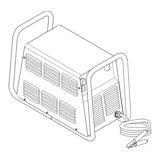
Page 50: Major External Replacement Parts
6.03 Major External Replacement Parts Item # Description Catalog # Cover with labels 9-8598 Rear Panel (Provide data tag information when ordering) for 208/230-Volt Power Supplies 9-8595 for 400-Volt, 460-Volt, and 600-Volt Power Supplies 9-8590 Tube, roll handle 9-8573 Hardware: Screw, 10-32 x 1/5"... -
Page 51: Front Panel Replacement Parts
6.04 Front Panel Replacement Parts Item# Description Catalog # Knob, Fluted, Skirted, 0.250 I.D. 9-8527 On/Off Rocker Switch, DPST 8-3258 Run/Set Switch, Rocker, SPST, Center Off 9-1042 Assembly, Pot/LED PCB 9-8004 Cable, Work, #6 AWG with Clamp, 20 Ft (6.1 m) 9-8528 A-03008 NOTE... -
Page 52: Left Side Internal Replacement Parts
6.05 Left Side Internal Replacement Parts Item # Description Catalog # Fuse for 208/230-Volt Power Supplies 9-8588 for 400-Volt Power Supplies 9-8602 for 460-Volt Power Supplies 9-8583 for 600-Volt Power Supplies 9-8638 Main Input Contactor for 208/230-Volt Power Supplies 9-8587 for 400-Volt, 460-Volt and 600-Volt Power Supplies 9-8554 Connector PCB... - Page 53 A-03188 NOTE Illustration may vary slightly from unit. Manual 0-2869 PARTS LISTS...
-
Page 54: Rear Panel Replacement Parts
6.06 Rear Panel Replacement Parts Item # Description Catalog # Assembly, Filter/Regulator 9-7514 Regulator/Filter Replacement Element 9-4414 Regulator Mounting Bracket 9-7589 Input Power Cable for 208/230-Volt Power Supplies (includes plug) 9-8596 for 400-Volt Power Supplies 9-8562 for 400-Volt CE Power Supplies 9-8553 for 460-Volt and 600-Volt Power Supplies 9-8593... - Page 55 Manual 0-2869 PARTS LISTS...
-
Page 56: Right Side Internal Replacement Parts
6.07 Right Side Internal Replacement Parts Item # Description Catalog # Assembly, Pressure Switch/Solenoid Sol1, PS1 9-8563 Assembly, CD PC Board 9-8552 Coil, CD Transformer 9-8582 Pilot Relay 9-8574 Fan, 220V, 115 CFM M1, M2 9-7687 Assembly, Main Transformer for 208/230-Volt Power Supplies 9-8589 for 400-Volt Power Supplies 9-8603... - Page 57 PCR Cover Bulkhead Heatsink Shroud Heatsink Heatsink Work Cable Shroud A-03189 NOTE Illustration may vary slightly from unit. Manual 0-2869 PARTS LISTS...
-
Page 58: Options And Accessories
6.08 Options and Accessories Description Catalog # Single-Stage Filter Kit (Includes Filter And Hose) 7-7507 Replacement Filter Body 9-7740 Replacement Filter Element 9-7741 Replacement Filter Hose (Not Shown) 9-7742 Two-Stage Air Line Filter Kit (Includes Hose & Mounting Screws) 7-7500 Bracket, Filter Mounting (Not Shown) 9-7535 Two-Stage Air Filter Assembly... -
Page 59: Appendix 1: Input Wiring Requirements
APPENDIX 1: INPUT WIRING REQUIREMENTS Non-CE CutMaster 75: CutMaster 75 Input Wiring Requirements Input Power Input Current Input Suggested Sizes (See Notes) Voltage Freq. 1-Ph 3-Ph 1-Ph 3-Ph Fuse (Amps) Wire (AWG) Wire (Canada) (Volts) (Hz) (kVA) (kVA) (Amps) (Amps) -
Page 60: Appendix 2: Sequence Of Operation (Block Diagram
APPENDIX 2: SEQUENCE OF OPERATION (BLOCK DIAGRAM) ACTION ACTION ACTION ACTION ON/OFF switch Close external RUN/SET RUN/SET switch to ON. disconnect switch. switch to RUN. to SET. RESULT RESULT RESULT RESULT AC indicator blinks for 8 Power to system. Gas flow stops. Gas solenoid open, seconds then steady on. -
Page 61: Appendix 3: Logic Pc Board Layout
APPENDIX 3: LOGIC PC BOARD LAYOUT TP12 TP10 A-03156 Logic Board Signals P1-27 Gate drive B signal P1-1 +12 vdc from Main PCB P1-28 Gate drive A return P1-2 +12 vdc from Main PCB P1-29 Gate drive A signal P1-3 DC Common P1-30 (-) out signal... -
Page 62: Appendix 4: Main Power Pc Board Layout
APPENDIX 4: MAIN POWER PC BOARD LAYOUT Fuse J32 J29 INPUT DIODE MAIN PCB ASSEMBLY 19x1753 460V 19x1777 208/230V 19x1778 400V 19x1806 600V IGBT A IGBT B A-03149 Main Power PC Board Signals J18-1 J11-1 L1 Input J18-2 J11-2 Not Used J18-3 28VAC B J11-3... - Page 63 J23-1 Not Used J43-1 +12vdc J23-1 Not Used J43-2 +12vdc J23-3 Not Used J43-3 DC Com J43-4 DC Com J24-1 Gas Solenoid J43-5 MC1 On J24-2 Gas Solenoid J43-6 Tip Sense J24-3 Pressure Switch J43-7 Run/Set J24-4 Pressure Switch J43-8 Press Good J24-5 Main Contactor...
-
Page 64: Appendix 5-A: 208/230 Volt Main Pc Board Wiring
APPENDIX 5-A: 208/230 VOLT MAIN PC BOARD WIRING To Heat- To Press Sw/ Copper Sink Temp To Power Out- To Inductor Solenoid/ Strap Switch put Board Temp Switch Contactor To PCR/On-Off Switch/ To Main Input Run-Set Switch Contactor Fuse To Fans To Pot/LED PCB Secondary Transformer... -
Page 65: Appendix 5-B: 400-V 460-V, And 600-V Main Pc Board Wiring
APPENDIX 5-B: 400-V 460-V, and 600-V MAIN PC BOARD WIRING To Heat- To Press Sw/ Sink Temp To Power Out- To Main Input To Inductor Solenoid/ Switch put Board Contactor Temp Switch Contactor To PCR/On-Off Switch/ Run-Set Switch To Fans Fuse To Pot/LED PCB Secondary... -
Page 66: Appendix 6: Cd Pc Board Layout
APPENDIX 6: CD PC BOARD LAYOUT A-03086 CD PC Board Signals J28-1 +12 vdc J28-2 CD Enable J28-3 Not Used J28-4 Not Used J28-5 J28-6 Not Used J28-7 Not Used J28-8 APPENDIX Manual 0-2869... -
Page 67: Appendix 7: Led/Pot Pc Board Layout
APPENDIX 7: LED/POT PC BOARD LAYOUT A-01206 Pot/LED PC Board Signals J14-1 +10 vdc from Logic PC Board (J27-1) Pot High J14-2 Current Control to Logic PC Board (J27-2) Pot Wiper J14-3 Return for Current Control from Logic PC Board (J27-3) Pot Low J14-4 12vdc (J27-4) J14-5... -
Page 68: Appendix 8: Igbt Circuit Pc Board Layout
APPENDIX 8: IGBT CIRCUIT PC BOARD LAYOUT IGBT A IGBT B TP2A TP2B TP1A TP1B A-03154 NOTE: Refer to Appendix 5-A for wiring connec- tions (208/230V Power Supplies). Refer to Appendix 5-B for wiring connec- tions (400V, 460V, 600V Power Supplies). APPENDIX A-10 Manual 0-2869... -
Page 69: Appendix 9: Input Diode Pc Board Layout
APPENDIX 9: INPUT DIODE PC BOARD LAYOUT A-03155 NOTE: Refer to Appendix 5-A for wiring connec- tions (208/230V Power Supplies). Refer to Appendix 5-B for wiring connec- tions (400V, 460V, 600V Power Supplies). Manual 0-2869 A-11 APPENDIX... -
Page 70: Appendix 10: Output Diode Pc Board Layout
APPENDIX 10: OUTPUT DIODE PC BOARD LAYOUT Output Diode B Output Diode A A-03152 NOTE: Refer to Appendix 11 for wiring connections. APPENDIX A-12 Manual 0-2869... -
Page 71: Appendix 11: Power Output Pcb Wiring Diagram
APPENDIX 11: POWER OUTPUT PCB WIRING DIAGRAM To Main Power To Bulkhead To Torch Switch To PCR PC Board To CD PCB To Output Inductor Output Output Diode A Diode B To Output A-03153 To CD Coil Work Cable Inductor Power Output PC Board Signals J39-1 - Out... -
Page 72: Appendix 12: 28Vac Circuit Diagram
APPENDIX 12: 28VAC CIRCUIT DIAGRAM Line Voltage Fuse 3 4 5 6 ON/OFF Switch 1 2 5 6 primary Auxiliary Transformer Voltage Protection +12vdc Main Power PC Board A-03071 APPENDIX A-14 Manual 0-2869... -
Page 73: Appendix 13: Maintenance Schedule
APPENDIX 13: MAINTENANCE SCHEDULE This schedule applies to all types of non-liquid cooled plasma cutting systems. Some systems will not have all the parts listed and those checks need not be performed. NOTE The actual frequency of maintenance may need to be adjusted according to the operating environment. Daily Operational Checks or Every Six Cutting Hours: Check torch consumable parts, replace if damaged or worn. -
Page 74: Appendix 14: System Schematic, 208/230-Volt Units
APPENDIX 14: SYSTEM SCHEMATIC, 208/230-VOLT UNITS INPUT DIODE IGBT PCB ASSEMBLY 19X1756 ASSEMBLY 19X1755 E12A E17A GATE 208/230V DRIVE COPPER SINGLE PHASE STRAP INPUT (78) GATE DRIVE (33) E19A E21A INRUSH +12VDC CHASSIS IGBT PCB ASSEMBLY 19X1756 E12B FILTERING +18V E17B GATE DRIVE... - Page 75 OUTPUT DIODE OUTPUT INDUCTOR ASSEMBLY E34B 19X1757 E39B MAIN E50B E(62) E48B E11A PILOT E(35) E53B E54B E56B J30 P30 E60B J31 P31 THRU SCREW TERMINAL OUTPUT DIODE ASSEMBLY E34A CHASSIS GND 19X1757 E39A E50A E11B E48A CD ASSEMBLY E53A 19X1751 E54A E56A...
-
Page 76: Appendix 15: System Schematic, 400-V, 460-V Units
APPENDIX 15: SYSTEM SCHEMATIC, 400-V, 460-V UNITS INPUT DIODE IGBT PCB ASSEMBLY 19X1756 ASSEMBLY 19X1811 E12A E17A GATE DRIVE 460VAC 3 PHASE INPUT 460VAC GATE DRIVE 1 PHASE INPUT E19A E21A +12VDC INRUSH IGBT PCB ASSEMBLY 19X1756 CHASSIS FILTER E12B CHASSIS 400V CE FILTERING... - Page 77 OUTPUT DIODE OUTPUT INDUCTOR ASSEMBLY E34B 19X1757 E39B MAIN E50B E(62) E48B E11A PILOT E(35) E53B E54B J30 P30 E56B E60B J31 P31 THRU SCREW TERMINAL OUTPUT DIODE ASSEMBLY E34A CHASSIS GND 19X1757 E39A E11B E50A E48A CD ASSEMBLY E53A 19X1751 E54A E56A...
-
Page 78: Appendix 16: System Schematic, 600-V Units
APPENDIX 16: SYSTEM SCHEMATIC, 600-V UNITS INPUT DIODE IGBT PCB ASSEMBLY 19X1815 ASSEMBLY 19X1811 E 1 2 A E 1 7 A GATE DRIVE 600VAC 3 PHASE INPUT GATE DRIVE E 1 9 A E 2 1 A INRUSH + 1 2 VD C IGBT PCB ASSEMBLY 19X1815 CHASSIS E12B... - Page 79 OUTPUT DIODE O U TPUT INDUCTOR ASSEMBLY E34B 19X1757 E39B M AIN E50B E(62) E48B E 1 1 A PILOT E(35) E53B E54B E56B J30 P30 E60B J31 P31 THRU SCREW TERMINAL OUTPUT DIODE ASSEMBLY E 3 4 A CHASSIS GND 19X1757 E 3 9 A E 5 0 A...
Need help?
Do you have a question about the CutMaster 75 and is the answer not in the manual?
Questions and answers