Table of Contents
Advertisement
Quaddrix QT-500 Series Stand Alone DVR
User Manual
(Rev. 20/12/2006)
This manual is applicable for QT-500-4, QT-500-8 and QT-500-16 embedded DVRs. Read this User
Manual carefully to ensure that you can use the device correctly and safely.
The contents of this Manual are subject to change without notice.
Advertisement
Table of Contents

Subscribe to Our Youtube Channel
Summary of Contents for Quaddrix QT-500-16
-
Page 1: User Manual
User Manual (Rev. 20/12/2006) This manual is applicable for QT-500-4, QT-500-8 and QT-500-16 embedded DVRs. Read this User Manual carefully to ensure that you can use the device correctly and safely. The contents of this Manual are subject to change without notice. -
Page 2: Table Of Contents
Index Chapter 1 Product Introduction ....................4 Summary .......................4 Features .........................4 Chapter 2 Installation ........................7 HDD Installation....................7 Rear Panel Description ..................8 External Alarm In/Out Connection...............9 Chapter 3 Operational Instructions ..................11 Front Panel......................11 IR Remote Controller ..................13 Menu Description....................16 3.3.1 Menu Items..................16 3.3.2... - Page 3 5.16 RS232 setup .......................88 5.17 Exceptions ......................95 5.18 Transaction Information.................96 Chapter 6 Utilities........................102 Save Parameters.....................102 Restore Parameters ..................103 Upgrade......................103 Hard Disk Management................104 Clear Alarm Out ....................105 Reboot.........................105 Power Off ......................105 View Log......................105 System Information..................109 Chapter 7 Firmware Upgrade....................110 FTP Server Setup.................... 110 Upgrade Mode....................
-
Page 4: Chapter 1 Product Introduction
H.264 hardware compression. For QT-500- 4 and QT-500-8 the total frame is 120FPS NTSC (100FPS PAL). For QT-500-16 the total frame 240FPS NTSC (first 8-ch 120FPS and second 8-ch 120FPS) or 200 FPS PAL (first 8-ch 100FPS and second 8-ch 100FPS) or. - Page 5 OggVorbis compression and bitrate is 16Kbps. QT-500-8 doesn’t have audio inputs. Compressed video and audio are synchronous. You can select either mixed stream or only video stream. Support video loop. Support CIF and QCIF resolution. Support multi area motion detection. Support OSD and changeable OSD position.
- Page 6 etc. Others Support IR Remote Control. Support multi-level user management. Network Support TCP, UDP, RTP, Multicast for network preview. Support PPPoE for board band dialup. Support PSTN for narrow band dialup. Support remote parameters setup. Alarm information can be sent to remote center. Network control PTZ.
-
Page 7: Chapter 2 Installation
Chapter 2 Installation Warning: Before you install the Hard Disks, please make sure the power of DVR is switched off. 2.1 HDD Installation Installation notice The DVR by factory default has not HDD installed. Based on the record schedule, you can calculate the total capacity you need (refer to Appendix HDD installation 1. -
Page 8: Rear Panel Description
Connect monitor, output video and Video Output menu. Audio Output 1 channel RCA (1.0 Vp-p, 75Ω) Audio input 4 channel RCA (1.0 Vp-p, 75Ω) QT-500-16 uses DB15 connectors. QT- Video Loop out 500-4 uses on board BNC connectors. VGA Interface VGA display. -
Page 9: External Alarm In/Out Connection
Connect RS-232 devices. Refer to RS-232 Appendix B for pin definition. UTP Network Connect network devices. Refer to Interface Appendix B for pin definition. PTZ connection. Refer to Appendix B for RS-485 pin definition. External Alarm 4/8/16 Alarm in. Input Relay Output 2/4 Alarm out AC Input... - Page 10 If you use AC, please open the jumper. There are 4 jumpers (JJ1, JJ2, JJ3 and JJ4) in DVR main board, corresponding with 4 alarm output. The default is closed. Warning: If you use AC input for relay output, please open the jumpers.
-
Page 11: Chapter 3 Operational Instructions
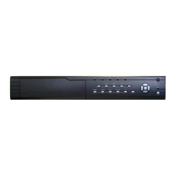
Chapter 3 Operational Instructions 3.1 Front Panel Index Type Name Description State READY DVR is ready. Lamps STATUS Green means you can use IR remote ALARM control. RECORD Red means there is alarm. NETWORK Twinkle in red means reading or writing HDD. - Page 12 EDIT 1. In edit state, delete the current cursor character; 2. [IRIS+] in PTZ control; 3. Select or × to enable or disable. PLAY 1. Local playback; 2. [AUTO] in PTZ control. 1. Manual record; 2. [SHOT] in PTZ control (adjust preset).
-
Page 13: Ir Remote Controller
3.2 IR Remote Controller Inde Name Description POWER Turnoff device. Enable/Disable IR remote control Same as numeric keys of Numeric Keys front panel. Same as EDIT key of EDIT front panel. Same as A key of front panel. - Page 14 Same as REC key of front panel. Same as PLAY key of PLAY front panel. Same as INFO key of INFO front panel. Same as VOIP key of VOIP front panel. Same as MENU key of MENU front panel. Same as PREV key of PREV front panel.
- Page 15 in “Display” menu) and then press [ENTER] key. If the “STATUS” lamp of DVR front panel is turned into green, it means you can use IR Remote Controller to operate this DVR Stop using IR Remote Controller When IR Remote Controller status is on, press [DEV] key again, the “STATUS”...
-
Page 16: Menu Description
3.3 Menu Description 3.3.1 Menu Items Menu Name Function Menu Name Function Camera name and position setup Adjust Brightness, Unit name Contrast, Hue and Device ID Saturation Require password OSD Display mode, Screen saver position and OSD Video standard Image format setup Display Brightness... -
Page 17: Menu Operation
PTZ linkage Alarm output and schedule PTZ parameters Preset setup RS232 RS232 parameters Sequence setup RS232 work mode Cruise setup Preview mode Add or delete user Switch time User Password setup or Preview Enable/Disable audio Password modification preview User rights setup Preview layout Restore parameters Upgrade firmware... - Page 18 Main Menu Description The main menu interface is following: There is one small rectangular frame named “Active Frame”. It can be moved from one icon to another by using [ ] or [ ] key. When the “Active Frame” is located on one icon, you can press [ENTER] key to enter into the secondary menu.
- Page 19 Each menu contains different kinds of items. There is a small rectangular frame named “Active Frame” which is pointing to the selected item. This “Active Frame” can be moved by [ ] or [ ] keys. There are such kinds of menu items: 1.
-
Page 20: Character Input
grey means it can be operated only after it is enabled. How to exit menu Press [PREV] key to exit menu and return to preview mode. 3.4 Character Input In the menu interface, if you enter into edit status (for example, in the “camera name”... -
Page 21: Chapter 4 Basic Operation Guide
Chapter 4 Basic Operation Guide 4.1 Power on Note: Please make sure the power supply matches DVR and AC cable connected correctly. Before switch DVR on, please connect one monitor with VOUT or VGA interface. Otherwise, you can not see graphic user interface and can not operate. If [POWER] lamp is off, please do as following: Step1: Connect AC cable correctly;... -
Page 22: Preview
4.2 Preview DVR will enter into preview mode after it is started. On preview screen, you can see date, time, camera name and camera status icon. Set system date and time in “Display” menu, referring to 5.2.9; Change camera name in “Image” menu, referring to 5.3.2. In the screen, it will display record and alarm status of each camera. - Page 23 Icon Icon Status Description Color White No video signal Yellow Video input Pink Manual recording Green Real time recording Blue Motion detect recording External alarm recording Camera alarm status is following:...
- Page 24 Icon Status Description Icon Color White Video signal lost Yellow View tampering alarm Pink Motion&External alarm Green No alarm Blue Motion alarm External alarm Press numeric keys to switch over individual camera preview. If DVR has less than 10 channels, press one numeric key to switch corresponding channel.
-
Page 25: User Name And Password
4.3 User name and password Note: When DVR is delivered from factory, there is only one default administrator named “admin”, and password is “12345”. The administrator’s name can not be modified, while the password can be modified. The administrator can create 15 users and define their user rights. - Page 26 Step 2: Enter into password modification menu Move the “Active Frame” to “Password” icon by using [ ] / [ ] keys. Press [ENTER] key to enter into following password menu:...
-
Page 27: Ptz Control
Step 3: Input new password Press [EDIT] key to enter into edit box. You can use numeric keys to input new password. The password can be null. It also can be 16 numerals. Press [ENTER] to exit edit box, and move to “Verify” item to input the verify password. - Page 28 There is “PTZ Control” prompt in the PTZ control interface. The displayed camera name means which channel’s PTZ is under control. For example, “Camera 01” means you are controlling the 1 camera PTZ. Select channel In PTZ control mode, you can press numeric keys to select channel. If DVR has less than 10 channels, press one numeric key to select.
- Page 29 Auto control key: [PLAY/AUTO] ; Wiper control key: [WIPER/MENU] ; Light control key: [LIGHT/F1] ; Auxiliary device control key: [AUX/F2] Preset Setting In PTZ control mode, press [REC/SHOT] key, and press the preset number (three numeric keys), DVR will adjust the corresponding preset number. Repeat pressing [REC/SHOT] key, and press the preset number, DVR will adjust that preset number.
-
Page 30: Manual Record
4.5 Manual Record Note: The user must have the corresponding right, DVR has HDD and HDD is formatted already. Manual record In preview mode, press [REC] key, in the pop-up login dialog, select the name and input the correct password, you can enter into the “Manual Record”... -
Page 31: Playback
motion detection recording). Red means network transmission. Orange means both recording and network transmission. Start/Stop: “ ” means you can start corresponding channel recording. “×” means you can stop recording. Start All: Press this button to start all channels recording. Stop All: Press this button to stop all channel recording. - Page 32 Playback Description This series DVR only supports one channel playback, Chan: Use [ ] or [ ] key to select one channel. Rec Type: Use [ ] or [ ] to select recorded files type. The file type options have “All”, “All Time”, “Motion Detect”, “Alarm” and “Manual”. Time Section: You can define the search time section.
- Page 33 Search: Search the matched recorded files and display them in the list box. If there is not matched file, a corresponding dialog box will be pop- Play by Time: Playback the recorded stream directly based on the time section. Select Page: In the file list box, each page will only display 8 files. If the matched files are more than 8, you can select page to list other files.
- Page 34 If the matched files are more than 8, you can use “Page No.” to select page (use numeric keys or [ ] [ ] keys to select page). In the file list box, use [ ] or [ ] keys to move the scroll bar to the file, press [ENTER] key to playback the file.
- Page 35 Operation when playback Playback picture: Playback At the bottom of image, there is an information bar and the following information is included: Volume, Play Progress, Play Speed, Played Time and File Total Time. Display/Hide information bar: [MENU] Open/Close sound: [PLAY] Adjust play progress: [ ] (Backward), [ ] (Forward).
-
Page 36: Backup Recorded Files
difference for actual play speed. Exit playback In playback interface, press [ESC] key to enter into preview mode. In playback interface, press [MENU] key to enter into main menu, press [REC] key to enter into manual record, and press [PTZ] key to enter into PTZ control mode. - Page 37 Backup the files that matched your requirement Step 1: Search the matched files In the playback interface, select one channel and record type, input the time section, move “Active Frame” to “Search” button, press [ENTER] key, DVR will start to find and list the matched files. Step 2: Select the files that you want to backup In the file list box, use [ ] or [ ] keys to move the scroll bar.
- Page 38 Playback the video segment You can use our file player software to playback the video segment in PC. You can find the player software in attached CD. (In the installation folder C:\Program Files\Quaddrix NetDVR\Player.exe) Exit playback interface Please refer to chapter 4.6.
-
Page 39: Shut Down Dvr
4.8 Shut Down DVR Note: Do not switch off the power directly in case of damaging HDD. The correct step is using “Power Off” in the “Utilities” menu, [POWER] key on the front panel or on IR Remote Controller. Shut down DVR normally Use menu Enter into “Utilities”... - Page 40 Shut down DVR abnormally Use the power switch of real panel When DVR is run, if you switch off the power, the HDD in DVR will be damaged. Please avoid such operation. Take away the power cable Please avoid taking away the power cable directly.
-
Page 41: Chapter 5 Parameters Setup Guide
Chapter 5 Parameters Setup Guide Only the users that have “Parameters Setup” right need read this chapter. When the following parameters are modified and saved, you must reboot the DVR to make the new parameters take into effective. Other parameters do not need to reboot. Any network parameters Stream type, resolution and record schedule External alarm sensor type... - Page 42 Move “Active Frame” to “User” icon, press [ENTER] key to enter into “User Management” menu. In the user name list box, only “admin” is existed. You can use [ ] key, move “Active Frame” to password edit box, and press [EDIT] key to enter into edit status.
- Page 43 “Verify password” edit box, input the verify password. Move “Active Frame” to “Confirm” button, and press [ENTER], if password and verify password are the same, the password will be saved and taken into effective. If password and verify password are not same, a warning message box will be appeared.
-
Page 44: Add And Delete User
5.2 Add and Delete User Enter into “User Management” interface. Add user The steps are following: Step 1: Enter into “User Management” menu Please refer to chapter 5.1 Step 2: Add new user name In the “User Management” menu, move “Active Frame” to “Add” button and press [ENTER] , in the pop-up dialog, input the new user name (refer to chapter 3.4), press [ENTER] and return “User... - Page 45 Step 3: Setup the password for new user After you add one new user, the password is null. You can skip this step if you do not want to change the password. In the users list box of “User Management” menu, use [ ] [ ] keys to select the new user name, then use [ ] key to the password edit box.
- Page 46 Operational rights are divided into “Local Rights” and “Remote Rights”. You can assign the necessary rights to the user. Use [ ] [ ] key to move “Active Frame” to the corresponding right items, press [ENTER] or [EDIT] key to enable or disable the item. “ ” means assigning the right to that user.
- Page 47 - Playback: Local playback and backup the recorded files; - Parameters Setup: Locally setup the DVR parameters; - Log: Locally view the log on DVR; - Utilities: Locally upgrade firmware, format HDD, reboot DVR and shut down DVR, etc. “Remote Rights”: - PTZ Control: Remote control PTZ;...
- Page 48 Remote Watch Administrator Can setting remote preview right option for each channel for users. Delete user In “User Management” interface, you can use [ ] [ ] keys to select one user, then use [ ] , move “Active Frame” to “Del” button, press [ENTER] , in the pop-up confirmation dialog, press “Confirm”...
-
Page 49: Unit Name And Device Id
5.3 Unit Name and Device ID Unit name In the “Display” menu: There is an item named “Unit Name”. The default unit name is “Embedded Net DVR”. Move “Active Frame” to unit name edit box, press [EDIT] key to enter into edit status, you can modify the unit name. About how to input characters, please refer to chapter 3.4. -
Page 50: Video Output Standard And Vga Setup
In “Display” menu, move “Active Frame” to the device ID edit box, in the edit status, you can use numeric keys to input new device ID. The device ID value is ranged among 01-100. After you finish the modification, press “Confirm” button to save and take effect or press “Cancel”... -
Page 51: Osd Setup
VGA setup There is one VGA interface at the real panel of DVR. You can use it to connect with VGA display. You can define VGA resolution, refresh frequency in “Display” menu. There following options: 1024*768/60Hz, 800*600/60Hz 800*600/75Hz. You can use [ ] [ ] key to select. Press “Confirm”... - Page 52 Display System Time You can setup display properties for each camera, including display status, position and format. Of course, you can copy the properties of one camera to all cameras. In “Image Setup” menu as following, select one camera: Display mode: There are several display modes: Opaque&Steady, Transparent&Steady, Transparent&Flashing, Opaque&Flashing,...
- Page 53 Here YYYY means year, MM means month, DD means day, W means weekday, hh menas hour, mm means minute and ss means second. Press [ENTER] to save and return “Image” menu or press to [ESC] abort modification. Copy parameters: After you setup the properties of one camera, you can copy it’s parameter to any other camera or all cameras.
- Page 54 Step 3: Press [ENTER] key to exit edit status. Move “Active Frame” to “Confirm” button, press [ENTER] to save the modification and you can see the new camera name. Press “Cancel” button or [ESC] key to abort. Setup Camera Name Position If you do not want to display camera name, just disable the check box beside camera name edit box.
-
Page 55: Video Parameters Setup
5.6 Video Parameters Setup For different camera and different background, in order to get the best video image, you need to adjust video parameters such as brightens, saturation, contrast and hue, etc. You can setup the camera individually, and also you can copy the video parameters of one camera to any other cameras. -
Page 56: Mask Area Setup
Step 4: You can copy the video parameters of current camera to any other cameras. Or you can repeat setp2 and step3 to adjust for any other camera. After adjust, in “Image Setup” menu, press “Confirm” button to save parameters and make them into effective. Otherwise, press “Cancel” button or [ESC] key to abort modification. - Page 57 Step 3: Enter into mask area setup interface: Enable the check box beside “Privacy Mask” item, you can press [EDIT] key to change the flag into “ ”, and active “Area” button. Move “Active Frame” to “Area” button on the right side of mask check box, press [ENTER] key to enter into mask area setup interface.
- Page 58 “Confirm” button to save the mask area, press “Cancel” button to abort. Here is the example for mask area function. If you disable the mask check box, you can cancel the mask area.
-
Page 59: View Tampering Alarm
5.8 View Tampering Alarm If you enable this function, when someone blocks the camera spitefully, DVR will make warning alarm. Step 1: Enter into “Image Setup” memo: Step 2: Select camera: Please use [ ] [ ] keys to select one camera. - Page 60 Step 5: View tampering alarm setup In “Image Setup” menu, move “Active Frame” to “Policy” button, press [ENTER] key to enter into “View Tampering Handle” menu: Step 6: Alarm schedule setup: When there is view tampering alarm happened, DVR will handle the alarm based on the schedule. You can set 4 periods for each day one week.
-
Page 61: Video Loss Alarm
Step 9: Save all cameras: If you want to setup other cameras, please repeat from step2 to step 8. In “Image Setup” menu, press “Confirm” key to save all cameras parameters. Press “Cancel” button or [ESC] key to abort. Select “Off” option for “View Tampering”, you can delete the view tampering area. - Page 62 Step 3: Enter into “Video Signal Loss Handle” interface: Move “Active Frame” to the list box on the right side of “Video Loss” item, use [ ] key to select “Handle” option and move “Active Frame” to the “Policy” button on right side. Press [ENTER] to enter into “Video Signal Loss Handle”...
-
Page 63: Motion Detection Alarm
Step 7: Save all cameras: If you want to setup other cameras, please repeat from step2 to step 6. In “Image Setup” menu, press “Confirm” key to save all cameras parameters. Press “Cancel” button or [ESC] key to abort. 5.10 Motion Detection Alarm If you enable this function, when there is motion detected, DVR will make alarm. - Page 64 “Policy Setup” button. If you select low sensitivity such as 0, only when there are great motion detection, DVR can response. On the other side, for high sensitivity such as 5, DVR will response with small motion detection. Step 4: Motion area setup: You must define motion areas so that DVR will response when there is motion in those areas.
- Page 65 Press [Enter] key to save and return “Image” menu. Press [ESC] to cancel. Clear all motion areas: Press [A] key to clear all motion areas of this channel. The keys used to setup motion areas are following: [ ] [ ] [ ] [ ] : Move yellow panel to any position; [EDIT] :Yellow panel and red panel switch key:;...
- Page 66 Step 6: Motion alarm record channel setup: When there is motion alarm happened, you can trigger related camera to start recording. In “Motion Alarm Handle” menu, you can select one or more record channels. Please use [ENTER] or [EDIT] key to enable the flag into “...
- Page 67 Step 8: Motion alarm handle method setup: You can select one or more handle methods such as “On Screen Warning”, “Audible Warning”, “Upload to Center” and “Trigger Alarm Output”. Description: If “On Screen Warning” is enabled, when there is motion alarm happened and DVR is in preview mode, DVR will pop-up the related camera.
-
Page 68: Preview Properties
5.11 Preview Properties In “Preview” menu, you can setup preview mode, screen switch time, enable or disable audio preview and preview layout. Step 1: Enter into “Preview” menu: In the main menu, move “Active Frame” to “Preview” icon and press [ENTER], you can enter into “preview”... - Page 69 Seconds”, “10 Seconds”, “20 Seconds”, “30 Seconds”, “1 Minutes”, “2 Minutes”, “5 Minutes” and “Never”. If you select “Never”, the preview image will not be switched automatically. For example, for 16 channels DVR, if you select “4 Screen” preview mode and “20 Seconds” switch time, DVR will cycle display 4 channels image every 20 seconds.
-
Page 70: Recording Setup
5.12 Recording Setup In main menu, there is an icon named “Recording”. You can enter into recording menu as following: “Recording” menu description: If HD Full: There are two options: “Overwrite” and “Stop recording”. If you select “Overwrite” option, when all HDDs in DVR are full, DVR will overwrite the earliest recorded files and continue recording. - Page 71 QCIF, CIF. QT-500-4 and QT-500-8 support QCIF and CIF. 100FPS (PAL) or 120FPS (NTSC), QT-500-16 support QCIF and CIF. First 8-ch has 100FPS and second 8-ch has 100FPS (PAL) or first 8-ch has 120FPS and...
- Page 72 Bit rate: You can select bit rate size for fixed bit rate type. It is the same as “Max Bit Rate”. Image Quality: If you select variable bit rate type, you can define image quality. There are 6 options: Highest, Higher, High, Average, Low and Lowest.
- Page 73 All day recording setup: Step 1: Enter into recording schedule menu In recording menu, use [ENTER] or [EDIT] key to enable record function (“ ” flag), press “Schedule” button to enter into recording schedule menu. Step 2: Select one day and enable all day recording option For “Day”...
- Page 74 Step 5: Save Press “Confirm” back to “Recording” menu. Press “Confirm” again to save the parameters and return main menu. None all day recording setup Step 1: Enter into recording schedule menu In recording menu, use [ENTER] or [EDIT] key to enable record function (“...
- Page 75 are: All Time, Motion Detect, Alarm, Motion&Alarm and Motion|Alarm. Note: The time periods in one day can not be repeated. Step 4: Copy to other days You can repeat step2 and step3 to setup for other days. Also you can copy the current day to other days.
-
Page 76: External Alarm Input And Relay Output
5.13 External Alarm Input and Relay Output For 4-channel DVR, there are 4 external alarm input and 2 relay output. For 8-channel DVR, there are 8 external alarm input and 4 relay output. For 16-channel DVR, there are 16 external alarm input and 4 relay output. In “Alarms”... - Page 77 Step 3: Enter into “Alarm in Handling” sub menu In the “Alarms” menu, there are two options for “Alarm Handling” item. One is “Ignore”, and the other is “Handle”. If you select “Handle” option, you can active “Policy” and “PTZ Linkage” buttons on right side.
- Page 78 Description: If “On Screen Warning” is enabled, when there is external alarm happened and DVR is in preview mode, DVR will pop-up the related camera. If you trigger more than one camera, DVR will pop-up them one by one every 10 seconds. When the external alarm is disappeared, DVR will restore preview mode.
- Page 79 chapter 5.15 for sequence setup. Cruise: Set the flag as “ ” to enable cruise. Please refer to chapter 5.15 for cruise setup. Press “Confirm” button to save and return “Alarms” menu. Press “Cancel” button or [ESC] key to abort and return “Alarms” menu. Note: Please make sure that the PTZ you are using can support preset, sequence and cruise functions.
- Page 80 Step 4: Setup alarm out schedule Like other schedule setup, you can set 4 time periods for one day and 7 days for one week. When you finish setup, press “Confirm” button to return “Alarms” menu. Step 5: Copy one alarm output parameters to other alarm output In “Alarms”...
-
Page 81: Network Parameters
5.14 Network Parameters If you want use network to access DVR, you must setup network parameters. Note: If any network parameter is modified, you must save and reboot DVR to make it into effective. In main menu, move “Active Frame” to “Network” icon and press [ENTER], you can enter into “Network”... - Page 82 DVR uses PPPoE function, also DVR can dialup into internet and this item will display the dynamic internet IP address. *Port: Network access port number, must be greater than 2000. *Mask: This is sub net mask. Gateway: The gateway IP is used to communicate in different network segments DNS address: If DVR uses PPPoE function, and get one dynamic IP address.
-
Page 83: Ptz
PPPoE: DVR support PPPoE dial-up function. Example: Use PPPoE function Step 1: Enter into “Network” menu. Step 2: Select NIC type. Step 3: Input port number. In the port edit box, use numeric keys to input port number. The port number must be more than 2000. Step 4: Input DNS IP. - Page 84 PTZ menu description Select channel: Select one PTZ camera. RS-485 parameters: Including baud rate, data bit, stop bit, parity, flow control, etc. These parameters must be the same as those of PTZ. Protocol. PTZ address: Each PTZ has one different address. PTZ type: DVR had the following PTZ protocol: YouLi, LinLin-1016, LinLin- 820, Pelco-p, DM DynaColor, HD600, JC-4116, Pelco-d WX, Pelco-D, VCOM...
- Page 85 ID is 2, the DVR PTZ address is set as ID 3. Preset setup: Preset is using one number to represent the camera’s position, zoom, focus and iris. Move “Active Frame” to “Setup” button on the right side of “Preset” item, press [ENTER] key to enter into preset setup menu.
- Page 86 and use [IRIS+] [IRIS-] [FOCUS+] [FOCUS-] [ZOOM+] [ZOOM-] keys to adjust iris, focus and zoom. After you finish adjusting, press [ENTER], then press “Save” button to save the preset number. You can repeat this step to setup other preset numbers. After you setup all preset numbers, press “Return”...
- Page 87 Press “Add” button to add one cruise point. Press “Confirm” button to save the cruise point into the sequence. After you finish setup the sequence number, press “StartSeq” to check the current sequence. Press “StopSeq” button to stop checking. You can delete cruise points in one sequence. After you finish sequence setup, press “Return”...
-
Page 88: Rs232 Setup
5.16 RS232 setup There is one RS-232 port at DVR rear panel. In main menu, move “Active Frame” to “RS232” icon and press [ENTER] key, you enter into “RS232” setup menu: RS232 menu description RS-232 parameters: Including baud rate, data bit, stop bit, parity, flow control, etc. - Page 89 PPP Mode: Only used when work mode is “PPP”. There are two options: “Active” and “Passive”. “Active” means DVR will dialup through PSTN. “Active” function is not available. “Passive” means DVR will wait for dialup. Callback mode: Only used when work mode is “PPP”. There are two options: “By Dialer”...
- Page 90 Step 2: Video setup In “Recording” menu, select the camera you want to transfer through PSTN. If you set CIF resolution, we suggest you set frame rate as 1 FPS. If you set QCIF resolution, the frame rate can be selected under 4FPS.
- Page 91 AT&S0=1 ---- Set Modem as answer ATE0 ---- Not display the input characters ATQ1 ---- Commit instruction and not display AT&W&W1 ---- Save parameters Step 5: Use DCE cable to connect Modem with DVR RS232 port. Setup at PC end Step 1: Setup Modem used on PC side.
- Page 93 Step 3: Establish the dialup connection Select the Modem connected with PC just like the dialup network connection, input the telephone number connected with DVR’s modem. Input the username, password. They must be the same as that DVR PPP setup. Step 4: During the dialup connection, it will give the message of “verification username...
- Page 94 IP address through Ping command, and can Ping-link DVR. Please refer to the following picture. Step 6: You can preview the image of 192.1.0.2 by using client-end software.
-
Page 95: Exceptions
5.17 Exceptions The exceptions can be handled at present include: hard disk full, hard disk error, illegal access, IP address conflict, network failure, and NTSC/PAL differ. Enter into “Exceptions” menu: Including the following handle methods: Audible Warning: DVR beep warning. Upload to Center: Send exception information to center host PC. -
Page 96: Transaction Information
5.18 Transaction Information The DVR can actively obtain or passively receive the credit card number from ATM machine linked through network or serial port, and credit card number can be overlay on live video, recorded and playback. The following description indicates how to carry out relevant parameter setting according to different links to ATM machine. - Page 97 You need to setup the following information: IP address of ATM machine Type of ATM machine Start & end position, length and the content of data message Start & end position and length of credit card number Start & end position and length of transaction type Transaction type and code When the ATM machine is sending transaction information to bank center, DVR will capture the data package through network, and analyze the data...
- Page 98 In this case, you must develop the software that is run in the ATM machine based on special protocol. The software will send the transaction information directly to the DVR. DVR will receive, analyze and overlay the text on live video. 2.
- Page 99 In the case, you must set the RS-232 of DVR as transparent channel mode as following: A software must be run in the ATM machine, and send the credit card number, transaction code to DVR through RS-232 port. Please provide detail ATM machine communication protocol for actual projects.
- Page 100 3. Receive the command sent by ATM through serial port In the case, you must set the RS-232 of DVR as transparent channel mode as following: Also, a software must be run in ATM machine, and send command to DVR through RS-232 port based on special communication protocol.
-
Page 102: Chapter 6 Utilities
Chapter 6 Utilities There many tools “Utilities” menu. Including “SavePara”, “RestorePara”, “Upgrade”, “Hard Disk”, “Stop Alarm Out”, “Reboot”, “Power Off”, “View Log” and “System Info”. Enter into “Utilities” menu: 6.1 Save Parameters Save factory default parameters into FLASH memory. You can reboot DVR to make them into effective. -
Page 103: Restore Parameters
6.2 Restore Parameters Restore factory parameters for DVR. The IP address, gateway and port number will not be restored. 6.3 Upgrade You can use this function to upgrade the firmware. Please confirm the language is matched. Press “Upgrade” icon, in the pop-up dialog, you can select either “FTP” or “USB”... -
Page 104: Hard Disk Management
If you select “FTP” mode, you will enter into “FTP Upgrade” menu: Input the ftp server IP and press [ENTER] key. The DVR will connect with FTP server through network and download the firmware file. If you select “USB” mode, please make sure you connect one USB flash memory with DVR and the firmware file is in it’s root directory. -
Page 105: Clear Alarm Out
Check HDD work status Capacity, Free space, Stand by or not, Normal status or not. Format HDD Before formatting stop all recording. After formatting, you must reboot DVR, otherwise DVR will not work normally. 6.5 Clear Alarm Out Clear the alarm output manually. 6.6 Reboot Reboot DVR. - Page 106 If you want to view the log based on default option, just press [ENTER] key. DVR will list all matched information. Also you can select options to search (By Type, By Date, By Type&Date). By Type To view log information of the assigned type. Type is divided into “Major type”...
- Page 107 For exception major type, the minor type includes: Video Signal Loss, Illegal Access, Hard Disk Error, Hard Disk Full, IP Conflict, DCD Lost. For example: The steps of viewing alarm log. Step 1: For “Query” item, select “By Type” to active “Major Type” and “Minor Type”...
- Page 108 Step 4: After finish searching, DVR will list the matched log information. Step 5: Press “Return” button back to “Utilities” menu. By Type&Date View one kind of log in the assigned time period. Step 1: Select “By Type&Time” for “Query” option to active “Major Type”, “Minor Type”...
-
Page 109: System Information
6.9 System Information Press “System Info” icon in “Utilities” menu, you can get DVR system information:... -
Page 110: Chapter 7 Firmware Upgrade
Chapter 7 Firmware Upgrade The DVR firmware is stored in FLASH ROM. You can use DVR upgrade function to write the firmware file (digicap) into FLASH. There are two cases that you need to upgrade DVR firmware. One is update old firmware. The other is when the code in DVR FLASH is crashed. Note: Make sure that the DVR and the firmware are compatible before the upgrade. - Page 111 2. Select “Logging” in the menu,choose Log Options in the sub menu, and give the choice as following: Select “Users/rights” under “Security” menu item. The following dialog box will be pop-up...
- Page 112 4. Create new user. Click “new user’. New user dialog pops up. Input user name “target”. Click “OK”. 5. In the password dialog, input password “target” in “New Password” “Verify Password” edit box. Click “OK” to save and exit the dialog box.
- Page 113 7. Next time, you need not setup again, just double click and open “wftpd32.exe” to upgrade the DVR/DVS firmware.
-
Page 114: Upgrade Mode
7.2 Upgrade Mode 1. Use client software to upgrade the firmware file. You do not need to use ftp server software. Please refer to the client software user manual for detail information. 2. Use “FTP” function of “Upgrade” sub menu in “Utilities” menu. You need one host PC to run FTP server software and place firmware file (digicap), and make sure DVR and PC are in the same sub net. - Page 115 firmware file are setup and run correctly. After upgrade finished, press any key to reboot DVR.
-
Page 116: Appendix A
Appendix A For Disk occupation calculation, you can use the Quaddrix HDD calculator, this tool available Quaddrix page in the Tech Support section. (HDD CALCULATOR) www.quaddrix.com... -
Page 117: Appendix B
Appendix B DVR Connect Cable Definition UTP network connect cable made method Material and tool One twist cable (8 pin, the length can be defined as to the actual demand, but must be within 100m), 2 standard RJ45 head, one tool for RJ45. Suggestion: have a network cable test tool to test each cable made. - Page 118 The corresponding relationship of the direct cable (2) Use the following method to make the cross network cable when DVR is directly connected with client-end PC. The corresponding relationship of cross cable...
-
Page 119: Connect Cable Made Method
RS-232 connect cable made method QT-500 has standard DB9 RS-232 interface, like PC COM port. Pin definition It means DVR input and O means DVR output. Name Description index Carrier Detect Receive Data Transfer Data Terminal Device Ready Ground Request to Send Clear Data... -
Page 120: Appendix C
Appendix C Specifications Model name QT-500-4 QT-500-8 QT-500-16 Video H.264 compression Preview PAL: 704*576 (4CIF), NTSC: 704*480 (4CIF) resolution Playback CIF/QCIF resolution Video input Video input BNC (Electrical Level: 1.0Vp-p, resistance: 75Ω) interface Video output 1 channel, BNC (Electrical Level: 1.0Vp-p, resistance: 75Ω) - Page 121 1 channel, RCA 1 channel, RCA (Linear Electrical (Linear Electrical Audio output Level, Resistance: Level, Resistance: 600Ω) 600Ω) Audio OggVorbis OggVorbis compression Audio compression 16Kbps 16Kbps rate 1 RJ45 10M/100M Self-adaptive Ethernet Interface Communicati 1 RS232 interface on interface 1 RS485 interface HDD IDE 2 IDE interface, can support 4 IDE HDD and each HDD can interface...
-
Page 122: List Of Recommended Dvr Peripherals
Appendix D List of Recommended DVR Peripherals USB CD-R/W: 1. BENQ external 5232WI-ok2 2. ASUS CRW-4824A + USB Converter case 3. SONY CD-R/RW CRX230AD + Converter cable 4. SONY CD-R/RW CRX225E + Converter cable 5. BENQ external EW162I-OK2 IDE CD-R/W: 1. - Page 123 6. MaxLine III 300GB ATA/133 HDD Seagate: 1. Barracuda 7200.7 40G 2. Barracuda 7200.7 80G 3. Barracuda 7200.7 120G 4. Barracuda 7200.7 160G 5. Barracuda 7200.7 200G 6. U Series 9 ce ST3160022ACE 160GB 7. DB35 Series ST3250823ACE 250GB 8. DB35 Series ST3300831ACE 300GB 9.
-
Page 124: Appendix E
Appendix E Quick Search Function Table Type Name Description Index User Create and delete users. System management has one default administrator. The Safety administrator can create 15 users function and define their rights. Password Modify password. 4.3&5. Management Format HDD, HDD information. management Recording Manual record, All time record,... - Page 125 PTZ control Control pan, tilt, zoom, focus and iris. Setup and adjust preset, sequence and cruise. Motion Motion detect area, sensitivity and 5.10 detection response policy setup. Alarm input Alarm input response policy, 5.13 schedule setup. Relay output Alarm output parameters setup. 5.13 Mask Sensitive mask area setup.
-
Page 126: Appendix F
Appendix F Troubleshooting Failure Possible reasons After plugging in power, turning on the Power cable power switch, “POWER” light in front broken. Panel does not turn on, and fan does not Power supply is work. broken. After plugging in power, turning on the 1) Front panel cable is power switch, “POWER”... - Page 127 2) Real board of DVR has problems. 3) Main board of DVR has problems. Cannot find the hard disk in reboot 1) Hard disk cable is process. broken. 2) The power cable of hard disk connected. 3) Hard disk is broken. No response in HyperTerminal interface.
- Page 128 Place the DVR in well ventilated space so that it operates within the allowed range of temperature and humidity as in specification. If the circuit board is wet, dust on circuit board can cause a short circuit. The circuit board, plug and socket, housing fan and housing should be cleaned by brushing regularly.
Need help?
Do you have a question about the QT-500-16 and is the answer not in the manual?
Questions and answers