Table of Contents
Advertisement
Quick Links
A Division of Star Headlight & Lantern Co., Inc.
INSTALLATION AND OPERATING
INSTRUCTION MANUAL
SS650 SIREN AMPLIFIER
LCS652 SIREN AMPLIFIER and
LIGHT CONTROLLER
455 Rochester Street Avon, NY 14414
Telephone Number: (585) 226-9025
Toll Free Fax: 888-478-2797
www.star1889.com
PLITSTR247 REV. D
7/28/05
Advertisement
Table of Contents

Related Manuals for Signal SS650

Summary of Contents for Signal SS650
- Page 1 A Division of Star Headlight & Lantern Co., Inc. INSTALLATION AND OPERATING INSTRUCTION MANUAL SS650 SIREN AMPLIFIER LCS652 SIREN AMPLIFIER and LIGHT CONTROLLER 455 Rochester Street Avon, NY 14414 Telephone Number: (585) 226-9025 Toll Free Fax: 888-478-2797 www.star1889.com PLITSTR247 REV. D...
- Page 2 This page intentionally left blank...
-
Page 3: Table Of Contents
Due to continuous product improvements, we must reserve the right to change any specifications and information contained in this manual at any time without notice. Signal Vehicle Products, Inc. makes no warranty of any kind with regard to this manual, including, but not limited to, the implied warranties of merchantability and fitness for a particular purpose. -
Page 4: General Description
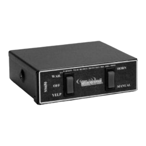
GENERAL DESCRIPTION The SS650 and LCS652 Siren Amplifiers are designed for single 100W speaker use. Each comes standard with the amplifier unit and switch panel all in one unit. The primary operating modes are Wail, Yelp, Standby, Manual, and Horn. Both the Horn and the Manual Control function will override all other functions, and can be utilized at any time via a rocker switch. -
Page 5: Unpacking
INSTALLER-SELECTABLE OPTIONS The SS650 and LCS652 have Phaser disable, Two-Tone enable, and Auxiliary Horn Polarity options that can be selected during installation. An internal jumper on the printed circuit board inside the amplifier case allows the installer to select these options. -
Page 6: Bottom View
AMPLIFIER COVER REMOVAL If you need to change any of the three options listed above you will need to access the inside of the siren. Remove the two Philips head screws located on the bottom of the unit and the two Philips head screws from the rear, and slide the cover off the back of the unit. -
Page 7: Mounting
MOUNTING AMPLIFIER The SS650 and LCS652 sirens may be mounted above the dash, below the dash, on a tunnel, or in a rack with the mounting u-bracket provided. Choose a mounting location convenient to the operator and away from any air bag deployment areas. -
Page 8: Electrical Connections
Power Connector You should also find enclosed with your siren a wiring harness. The SWH-27 wiring harness is used in the SS650. The SWH-83 comes with the LCS652. They come with a 12-port connector using six or nine different colored leads. - Page 9 Be sure to use minimum size #16 AWG wire. Red: (Pin 1 for SS650 and Pins 1, 4 & 8 for LCS652) Power - Connect the red wires to +12 VDC. It is strongly recommended that you connect to a +12 VDC source that is present only when the vehicle ignition is in the on position.
-
Page 11: Operation
OPERATION GENERAL This unit is designed for easy operation under the stress associated with high-speed pursuit. Most siren functions are accessible with one simple motion without repetitive activation of switches or automatic timed switching that can interfere with desired operation. MODE SWITCH The three-position rocker switch on the left controls the primary operating mode of the siren. -
Page 12: Manual
SIREN OUTPUT: Selector Switch Speaker Pressing Manual Pushbutton Position: Output Wail Wail Yelp Yelp Yelp Phaser (or Two-Tone) (Remains Yelp if Phaser disabled) Creates a manual WAIL tone while No Output button is being held that sweeps down when the button is released. (NOTE: PHASER may be optionally disabled via program jumpers. -
Page 13: Troubleshooting
TROUBLESHOOTING Symptom Possible Cause Check No power Power source not turned on Is ignition switch in AUX or ON position? Connector loose Do you hear a “pop” when turned on? Amplifier 15A fuse blown Is power hooked up backwards? Positive ground vehicle? Is an external fuse or circuit breaker used? Loose connection at power... -
Page 14: Specifications
(1) Positive, (1) Negative, (2) Speaker, and (1) auxiliary Horn. LCS652 only: (2) Additional Positive Size 2” High, 6” Wide, 5¼” Deep Boxed Weight 3.5 lbs. PARTS The following parts are available from Signal Vehicle Products: Part Description P30235-19P Amplifier Top Cover P30234-19P Amplifier Bottom Mounting Plate... -
Page 15: Limited Warranty
During this warranty period the obligation of Signal Vehicle Products is limited to repairing or replacing, as Signal Vehicle Products may elect, any part or parts of such product which after examination by Signal Vehicle Products is determined to be defective in material and/or workmanship. - Page 16 www.star1889.com -14-...
Need help?
Do you have a question about the SS650 and is the answer not in the manual?
Questions and answers