Table of Contents
Advertisement
Advertisement
Table of Contents

Related Manuals for SmartSight S1500e

Summary of Contents for SmartSight S1500e
- Page 1 S1500e Series User Manual...
- Page 3 S1500e Series Firmware Release 2.60/3.0 User Manual...
- Page 4 Publication date: December 22, 2003 The SmartSight logo, SmartSight, S1500e, S1502e, S1504e, S1508e, nDVR, and Versalis are trademarks of SmartSight Networks Inc. Any other product names mentioned herein are the trademarks or registered trademarks of their respective owners. While every reasonable effort has been made to ensure the accuracy of this document, SmartSight makes no warranty of any kind and assumes no responsibility for errors and omissions.
-
Page 5: Table Of Contents
Related Documentation ........viii Related SmartSight Products ......viii About Us ............. ix Warranty ............. x Chapter 1 Overview ..........1 About the S1500e Series ........2 Physical Characteristics ........2 Security ............2 Video .............3 Shipment .............4 Unit Casing Description ..........5 S1500e and S1502e .........5 S1508e ............6... - Page 6 Audio ............21 Performing a Hardware Reset ........ 24 Status LEDs ............25 System LED on the S1500e and S1502e ..... 26 System LED on the S1504e and S1508e ..... 27 Video LEDs on the S1504e and S1508e ....27 Chapter 4 Setting Parameters with the CLI ..
-
Page 7: Preface
Preface The S1500e Series User Manual presents the information and procedures on installing, configuring, and using the SmartSight S1500e series video servers. This guide covers the following firmware versions: Unit Firmware version S1500e 2.60 S1502e 2.60 S1504e S1508e... -
Page 8: Who Should Read This Manual
This manual contains all the information needed to install, configure, and use an S1500e series unit. Contents The S1500e Series User Manual is divided into the following chapters: Overview—Provides a brief description of the features of the S1500e series and illustrations of their casings. -
Page 9: Conventions
How to Use this Manual The manual also includes the following appendixes: Factory Default Configuration—Lists the default parameter values of the S1500e series unit. RS-485 Multidrop Connections—Presents the 2-wire and 4-wire RS-485 multidrop connections. DHCP Support and APIPA Service—Explains how the dynamic host configuration protocol server and the Microsoft APIPA service work. -
Page 10: Related Documentation
Furthermore, a paper copy of the Quick Installation Guide is included with your order. Related SmartSight Products You may use the S1500e series units along with the nDVR software. This user-friendly video management and storage software is able to view, record, and play back video simultaneously from any location. -
Page 11: About Us
User Manual About Us About Us Positioned at the intersection of wireless and digital video streaming, SmartSight, based in Quebec (Canada), is dedicated to developing video solutions for CCTV and IP networks that deliver real-time video content over LAN, wireless LAN, WAN, Internet, and 2.5/3 G cellular networks. SmartSight’s networked digital video solutions enable video management and monitoring primarily for security, surveillance, and asset protection in airports, government,... -
Page 12: Warranty
Preface S1500e Series Warranty Each standard product manufactured by SmartSight is warranted to meet all published specifications and to be free from defects in material and workmanship for a period of one year from date of delivery as evidenced by SmartSight packing slip or other transportation receipt. -
Page 13: Chapter 1 Overview
(LANs and WANs) or the Internet using ISDN, PSTN, or xDSL routers. It is built on open standards to provide long-term investment protection. The S1500e series is part of the Versalis solution that provides compelling video-over-IP solutions to the CCTV industry. -
Page 14: About The S1500E Series
(4800 baud, 8 data bits, no parity, 1 stop bit). Physical Characteristics An S1500e server can be a receiver (-R) or a transmitter (-T); a single receiver and four transmitter units are available. Here is an overview of their features:... -
Page 15: Video
IP network on it. However, you can configure it with SConfigurator. For more information about this security feature, refer to the SConfigurator User Manual. Video The S1500e series units can have the following video resolutions: Resolution Unit Number of... -
Page 16: Shipment
S1504e or S1508e transmitter with a video output port (to be available on a future firmware release) For the S1500e and S1502e: A 12V DC external power supply (for North America only) For the S1504e and S1508e: Rack mount brackets... -
Page 17: Unit Casing Description
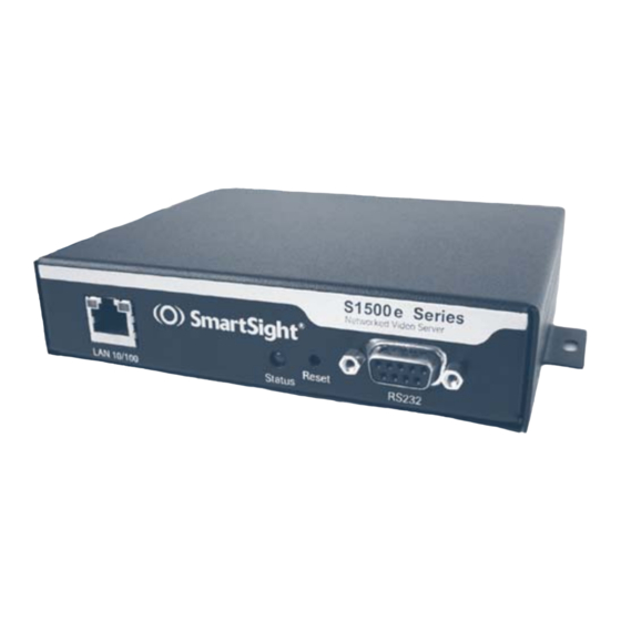
User Manual Unit Casing Description Unit Casing Description The S1500e electronics are enclosed in a non-weatherproof extruded aluminium casing that is not meant for outdoor use. The front and back panels vary depending on the unit. S1500e and S1502e The front panel consists of:... -
Page 18: S1508E
Overview S1500e Series S1508e The front panel consists of: An RJ-45 jack Eight video status LEDs A system status LED A reset button A female DB-9 connector for RS-232 use S1508e LAN 10/100 Video Status RS232 Status Reset System status... -
Page 19: S1504E
User Manual Unit Casing Description The DIP switches determine if a video input is terminated in the unit (with a load resistance of 75 ohms) or left in high impedance for looping (hi-z). Hi-z ON 1 75 ohms Position 1 is for the video input to the left of the switch, whereas position 2 is for the video input to the right. - Page 20 Overview S1500e Series The back panel consists of: Multipole connectors for power, input/output, and RS-422/485 An optional video output BNC connector Eight video input BNC connectors Four DIP switches for the video input terminations Optional audio connectors Audio (optional) 12V DC...
-
Page 21: Chapter 2 Network Planning
Network Planning To allow optimal configuration, you must properly plan your network. - Page 22 100Base-T to SC converters, which can offer a 1.25-mile (2-km) range. The S1500e supports a streaming method called multicast, which permits more than one receiver unit to view a video stream at any one time. Here is a typical connection for a point-to-multipoint application.
-
Page 23: Configuring And Installing The Unit
Configuring and Installing the Unit To prepare your S1500e unit for operation, you have to perform a series of steps: Basic configuration, mainly for communication and serial connection Physical installation in its final location Alarm and audio configuration Connection to the serial ports Remember that your unit is an indoor product that cannot support an outdoor environment. -
Page 24: Configuring The Unit
Network card Serial port Setting Unit Parameters The first step in installing an S1500e system is to change the IP address of the unit to ensure compatibility with an existing network. The default IP addresses of all units are based on the APIPA service and will be in the range 169.254.X.Y, where X and Y are relative to the MAC address... - Page 25 To set the parameters of a unit: In a lab, unpack the unit and set it on a table. Plug the S1500e IP connector directly to a computer using a crossover cable or to your LAN using a straight-through cable.
- Page 26 For more information about DHCP, see page 47. Click OK. The unit reboots with its new network configuration. In the Units tab, click Discover. The new S1500e unit appears.
-
Page 27: Performing A Point-To-Point Connection
(for instance, camera or PTZ keyboard). For more information, refer to the SConfigurator User Manual. The S1500e initial configuration is now complete. You perform further configuration with either the SConfigurator or nDVR software, both from SmartSight. Performing a Point-to-Point... - Page 28 Configuring and Installing the Unit S1500e Series Choose the Connections tab, then click Add. The Connection Creator window appears. Select a transmitter in the left column and a receiver in the right one. To disable I/O data transmission (for example, alarms), clear Forward I/O.
-
Page 29: Installing The Unit
The number of video inputs varies depending on the unit in the S1500e series. Each source requires a means to output the video. Depending on the context, you require up to eight S1500e receivers to output the video: Point-to-point analog extension—One receiver per video... -
Page 30: Performing Serial Connections
Configuring and Installing the Unit S1500e Series Performing Serial Connections The S1500e series units hold connectors for two serial ports: RS-232 and RS-422/485. RS-232 Use the following wiring scheme to plug a serial cable to the DB-9 connector in the back of the unit:... - Page 31 User Manual Performing Serial Connections For the RS-422/485 bidirectional protocols, the setup is the following: LAN (local area network) Transmitter Receiver RS422/485 RS422/485 Video Video Audio Audio Tx+ Tx- Rx+ Rx- Gnd Tx+ Tx- Rx+ Rx- Gnd Tx+ Tx- Rx+ Rx- Gnd Tx+ Tx- Rx+ Rx- Gnd For the RS-422/485 Pelco P or D protocols, you connect the serial port the following way:...
-
Page 32: Configuring The I/Os
You cannot program audio and alarms at the same time, since both contexts require input 1. Since the S1500e units are mostly used with nDVR, you will perform most configuration and activation steps in this software. Otherwise, in a point-to-point connection, you use... -
Page 33: Alarms
User Manual Configuring the I/Os Alarms All S1500e units can generate and receive alarms. To configure alarms in a point-to-point configuration, you plug the event sensor to the input 1 and ground terminals of the connector (typically on a transmitter unit), and your alarm system to the Out section of the receiver. - Page 34 Configuring and Installing the Unit S1500e Series The PTT/PTL transmission mode requires specific hardware configuration: To activate the audio reception circuit (for PTL) on receiver units, you have to short the input 1 and ground terminals on the multipole connector. You cannot activate PTL on transmitters.
- Page 35 User Manual Configuring the I/Os Audio Input/Output Types The unit supports the following audio input types: Line-in—To use a 3.5 mm jack (default). In this mode, you need a pre-amplifier. You connect the audio input on the unit to the Line-out connector on the pre-amplifier.
-
Page 36: Performing A Hardware Reset
To reset the parameters to their factory defaults without performing a hardware operation, see page 38. Following a reset, you will need to reprogram the S1500e unit (for instance, its IP address and VSIP port) for proper operation within its network. -
Page 37: Status Leds
Power down the unit and call SmartSight technical support for assistance. Flashing green-red LED not during a firmware update (S1500e and S1502e only): The unit is in backup mode; you will need to perform a firmware... -
Page 38: System Led On The S1500E And S1502E
Configuring and Installing the Unit S1500e Series System LED on the S1500e and S1502e The system status LED provides detailed information on the current state of the system, including video. Condition Indication -T -R Steady red The unit is powering up. -
Page 39: System Led On The S1504E And S1508E
User Manual Status LEDs System LED on the S1504e and S1508e The system status LED provides detailed information on the current state of the transmitter, excluding video. Condition Indication Steady red The unit is powering up. Flashing red (1 sec. The IP address of the unit is already assigned to intervals) another unit in the network. -
Page 41: Setting Parameters With The Cli
Setting Parameters with the CLI The S1500e units come with a simple command line interface (CLI) for configuration purposes. The CLI is hierarchically organized, with menus, sub-menus, and individual options representing configuration parameters. Only the parameters that you are likely to change are... -
Page 42: Getting Started
You can use the Telnet command to open the command line interface of the S1500e. Note Ensure that your PC and the S1500e unit are in the same IP subnet. To enter the CLI with Telnet: Start the Command Prompt Windows accessory. -
Page 43: Using The Cli
User Manual Getting Started The CLI main menu appears. The CLI has a timeout that is triggered after three minutes of inactivity. When the timeout occurs: The “Thank you for using the SmartSight CLI.” message appears at the command line. You are brought back at the Command Prompt command line. -
Page 44: Serial Port
S1500e Series Serial Port The Serial Port menu enables you to establish the proper settings ensuring compatibility between the S1500e unit and your serial equipment (for example, dome, keyboard, matrix, multiplexer, or access card). For more information about the serial port settings of the specific product with which you want to interface, refer to its user manual or contact your product manufacturer. -
Page 45: Access Management
RS-422/485 Operating Mode The operating mode setting enables you to establish the way your RS-422/485 serial equipment will interface with the S1500e unit. The supported modes are: RS-422 4 Wires RS-485 4 Wires RS-485 2 Wires... -
Page 46: Security
Setting Parameters with the CLI S1500e Series Security The Security menu holds commands relative to the protection of the unit. It allows you to control: Firmware updates through the IP network Access to Telnet IP Firmware Update You can prevent firmware updates to be performed on your unit through the IP network. -
Page 47: System Status
Telnet, therefore avoiding eavesdropping on the network. System Status The system status information indicates the current values of internal S1500e parameters, including the unit’s serial number and firmware version. A transmitter and a receiver connected together need to be running the same firmware version. -
Page 48: Network
For more information about DHCP, see Appendix C, page 47. You can set this option only if the S1500e is connected to a network that uses a DHCP server. Local IP Address The IP address is the identifier of the S1500e on the network. -
Page 49: Advanced Menu
User Manual Advanced Menu Gateway The gateway represents a network point that acts as an entrance to another network. Warning Never use the IP address of the unit as the gateway value. Ping Request Ping is a basic Internet program that allows you to check that a particular IP address exists and can accept requests. -
Page 50: Load Default Configuration
Setting Parameters with the CLI S1500e Series Identifying a Unit To recognize an S1500e among a large set of units, you can make its system status LED flash red rapidly. To identify an S1500e unit: From the main menu, choose Advanced, then press Enter. -
Page 51: On-Screen Display (Osd)
On-Screen Display (OSD) The S1500e receiver units display information on a video monitor. -
Page 52: Quadrant 2: Smartsight Logo And Video Message
On-Screen Display (OSD) S1500e Series The information displayed on the video monitor can be broken down into four quadrants as follows: Quadrant 1 Quadrant 2 Quadrant 4 Quadrant 3 Quadrants 1 and 4 are unused. If a video source is not plugged into a currently streaming receiver, quadrants 1 and 4 turn to red and quadrants 2 and 3 become blue/black. -
Page 53: Quadrant 3: Receiver Setup Details
User Manual Quadrant 3: Receiver Setup Details Quadrant 3: Receiver Setup Details Quadrant 3 displays basic S1500e-R configuration details, including serial port and network setup. This information is displayed during 45 seconds. For example: S1500e ver: 2.60- build 380 Comm: 4800, 8, N, 1 232f-d IpAddr: 192.168.135.97... -
Page 55: Appendix A Factory Default Configuration
Factory Default Configuration This appendix lists the factory default configuration of the S1500e units. - Page 56 Factory Default Configuration S1500e Series The S1500e is programmed at the factory with the following configuration: Type Configuration Serial port Bit rate: 4800 bauds Parity: none RS-422/485 operating mode: RS-422 4-wire Access management User name: USERNAME Password: PASSWORD User accounts: Disabled...
-
Page 57: Appendix Brs-485 Multidrop Connections
RS-485 Multidrop Connections Two multidrop configurations are available: Four-wire Two-wire... - Page 58 RS-485 Multidrop Connections S1500e Series The four-wire configuration, which can be used for both RS-422 and RS-485, is: LAN (lo cal ar ea n et w o r k) RS422/485 RS422/485 Video Video Audio Audio The two-wire configuration, for RS-485 only, is:...
-
Page 59: Appendix Cdhcp Support And Apipa Service
DHCP Support and APIPA Service DHCP (dynamic host configuration protocol) allows devices and computers connected to a network to automatically get a valid IP configuration from a dedicated server. The APIPA (automatic private IP addressing) service, available on the Windows operating systems, enables a device to assign itself a temporary IP address. - Page 60 DHCP Support and APIPA Service S1500e Series At startup, a unit searches for a valid IP network configuration. The unit requires this configuration prior to starting its functions. The network configuration for SmartSight units consists of: An IP address A subnet mask...
-
Page 61: Appendix Ddte And Dce Connections
DTE and DCE Connections Before connecting a SmartSight unit to other serial equipment, you need to determine if they are DTE (data terminal equipment) or DCE (data communication equipment). Here are examples of both equipment types: DCE—SmartSight units, modems DTE—Computers, switches, multiplexers, cameras, keyboards... - Page 62 DTE and DCE Connections S1500e Series You need to know which equipment type your other serial device is in order to connect it correctly to the S1500e unit, which is a DCE. In the following descriptions: Voltage is measured when no data is transferred on the Rx and Tx pins.
- Page 63 User Manual DTE and DCE Connections Connecting DTE and DCE When connecting two modules of the same type, you have to cross the data wires to create proper communication. On the other hand, when connecting a DTE with a DCE, a straight cable is required.
-
Page 65: Appendix Ecli With Sconfigurator
CLI with SConfigurator The SConfigurator console enables you to easily access the CLI (command line interface) tool to configure and customize your S1500e unit. - Page 66 SConfigurator directly from the CD or copy the executable file first on your hard disk. To access the CLI with the SConfigurator console: Connect the S1500e unit to a COM port of the computer using a serial cable. Start SConfigurator.
- Page 67 User Manual CLI with SConfigurator Close the SmartSight Console window. Warning The Disconnect button is used to terminate the connection to the SConfigurator console, not to exit from the CLI. Clicking it does not free the RS-232 connection and does not save your settings.
-
Page 69: Appendix Fcli With Hyperterminal
CLI with HyperTerminal HyperTerminal is the Windows system tool for connecting to other computers, Internet Telnet sites, bulletin board systems (BBSs), online services, and host computers. You can use it to access the CLI (command line interface) of your unit. - Page 70 You have to perform the following operations before being able to use HyperTerminal to access the CLI: Connecting the S1500e unit to a COM port of the computer using a CAB9P serial cable with a DB-9 end Powering the S1500e unit Establishing a connection Setting the parameters of the computer’s serial port...
- Page 71 User Manual CLI with HyperTerminal To set the parameters of the serial port: From the main HyperTerminal window, choose File > Properties. The connection_name Properties window appears. In the Connect using field, select the COM port you are using for the connection.
- Page 72 To activate the connection: From the main HyperTerminal window, choose Call > Call. You can now use the CLI to configure your S1500e unit. To access the CLI with HyperTerminal: Press Ctrl+Break, then the space bar for a few seconds.
- Page 73 User Manual CLI with HyperTerminal To end the CLI work session: Save the settings by entering s at the main menu, then pressing Enter. Exit the CLI by entering q at the main menu, then pressing Enter. Close the HyperTerminal window.
-
Page 75: Appendix G Audio Pinouts
Audio Pinouts This appendix presents information relative to the 3.5 mm stereo plugs used for audio on the units. - Page 76 Audio Pinouts S1500e Series Here is the pinout of the stereo jacks for audio input: Ground (shield) Mic/Line-in Mic bias (not connected for line-in) Mic bias (not connected for line-in) Mic/line-in For audio output, the jacks are configured the following...
-
Page 77: Appendix H Technical Specifications
Technical Specifications... - Page 78 Technical Specifications S1500e Series Here are the S1500e technical specifications: Video Compression MPEG-4-based Frame rate S1500e: 1–30 fps programmable (full motion) S1502e: 2 at 1–15 fps programmable (full motion) S1504e: 4 at 1–30 fps programmable (full motion) S1508e: 8 at 1–15 fps...
- Page 79 Others: DNS and DHCP client Security SSL-based authentication Power Supply voltage 12V DC ±10% Consumption S1500e, S1502e: 6W max. (500 mA max. at 12V DC) S1504e, S1508e: 31W max. (2.6A at 12V DC) Physical Enclosure Metal case with flange mount (black...
-
Page 81: Glossary
Glossary This glossary is common to all SmartSight products. - Page 82 Glossary S1500e Series Access Point A device acting as a communication switch for connecting wireless units to a wired LAN. Access points are mainly used with wireless transmitter units to transfer wireless content onto the wired IP network. APIPA (Automatic Private IP Addressing) A feature of...
- Page 83 User Manual Glossary DVR (Digital Video Recorder) A device (usually a computer) that acts like a VCR in that it has the ability to record and play back video images. The DVR takes the feed from a camera and records it into a digital format on a storage device which is most commonly the hard drive.
- Page 84 Glossary S1500e Series NTSC (National Television Standards Committee) The North American standard (525-line interlaced raster-scanned video) for the generation, transmission, and reception of television signals. In addition to North America, the NTSC standard is used in Central America, a number of South American countries, and some Asian countries, including Japan.
- Page 85 2.4 GHz frequency band. S1100w The SmartSight outdoor wireless video transmitter operating on the 5 GHz frequency band. S1500e Series The SmartSight series of Ethernet video servers (receiver and transmitter) designed for video monitoring and surveillance over IP networks.
- Page 86 Also called encoder. Video Server A unit transmitting or receiving video signals. The SmartSight wireless servers are the S1000w and S1100w units; the Ethernet servers are the S1500e series and S1600e units. VSIP (Video Services over IP) A proprietary communication protocol for sending messages between a computer and a SmartSight unit, or between two units.
-
Page 87: Index
Index casing of the unit 5–8 Numerics CD, Utilities viii 3.5 mm plug 21, 64 certificate, SSL 2, 35 characteristics of the unit 2 abnormal power-up checking for the SSL feature 35 condition 25 CIF resolution 3 access management CLI (command line interface) menu in the CLI 33 access with account, user 33... - Page 88 Index S1500e Series connection DCE/DTE 49 gateway 37 HyperTerminal and unit 58 global security profile 34 multidrop 45 point-to-point 15 RS-232 18 hardware reset 24, 43 RS-422/485 18, 45 HyperTerminal 57 SConfigurator and unit 54 connector I/O, alarm or audio 20–24...
- Page 89 5–8 multidrop connection 45 parity 33 pinout 18 passkey, SSL 35 password for serial connection 33 S1500e panels 5 SSL 35 S1500e-R for Telnet connection 33 OSD 39–41 Pelco protocol pinout 19 panels 5 ping request 37...
- Page 90 Index S1500e Series updating firmware, preventing 3, 34 technical specifications 65–67 user account 33 technical support ix user name 33 Telnet Utilities CD viii accessing the CLI 30 preventing access 3, 34 temporary IP address 47 version of firmware v, 15, 35...
-
Page 91: Compliance
Compliance... - Page 92 Cet appareil numérique de la classe A est conforme à la norme NMB-003 du Canada. EN 55022 Statement This is to certify that the SmartSight Model S1500e and S1502e Ethernet video servers are shielded against the generation of radio interference in accordance with the application of Council Directive 89/336/ECC, Article 4a.
- Page 93 H7L 4S4 Canada Declares under sole responsibility that the product: Product name: Ethernet video server Model number: S1500e, S1502e To which this declaration relates is in conformity with the following standards or other documents: EMC Directive 89/336/EEC: EN55022:1998 class A...
- Page 95 SmartSight Networks Inc. 1800, Berlier Street Laval (Quebec) H7L 4S4 Canada...
Need help?
Do you have a question about the S1500e and is the answer not in the manual?
Questions and answers