
Related Manuals for Axia CHT941

Summary of Contents for Axia CHT941
- Page 1 8x8 Analog Node 8x8 AES Node Installation & User’s Guide Version 2.0, February, 2007...
-
Page 2: Important Safety Information
IMPORTANT NOTE: Important Safety Information Axia nodes are intended for use with an Ethernet Switch that supports multicast and QOS (Quality To reduce the risk of electrical shock, do not expose of Service). On a non-switched Ethernet hub, or a this product to rain or moisture. -
Page 3: Customer Service
Customer Service We support you... By Phone/Fax in the USA. • Customer service is available from 9:30 AM to 6:00 PM USA Eastern Time, Monday through Friday at +1 216.241.7225. Fax: +1 216.241.4103. By Phone/Fax in Europe. • Service is available from Axia Europe in Germany at +49 81 61 42 467. Fax: +49 81 61 42 402. By E-Mail. -
Page 4: Warranty
Notice About This Manual All versions, claims of compatibility, trademarks, etc. This manual covers the details of the Axia 8x8 Ana- of hardware and software products not made by Axia log and 8x8 AES nodes. However it is assumed in mentioned in this manual or accompanying material this document that you are familiar with Livewire’s are informational only. -
Page 5: Table Of Contents
Table of Contents The 8x8 node home page ....10 The Configure Sources (local inputs) page ..10 Warranty ......iv Source Name and Channel . - Page 6 add an Ethernet switch and more interfaces to build a A Note From The Founder/CEO of Telos system with as many inputs and outputs as you want. It’s been a tradition since Telos’ very first product, the Audio may be routed directly from interface to inter- Telos 10 digital phone system, that I share a few words face or to other PCs, so you now have an audio routing with you at the beginning of each manual.
-
Page 7: A Note From The President Of Axia
considering that PCs everywhere were being networked, A Note From The President of Axia fast becoming the world’s most popular and powerful 20 years ago, I designed my first broadcast console communication tool. for PR&E. I look back on that time with great fondness; Then a group of Telos engineers developed a method we were building bullet-proof boards for the world’s of using Ethernet to network real-time audio devices, al-... - Page 8 Version 2.0, February, 2007...
-
Page 9: Chapter One
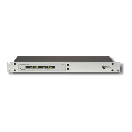
Chapter One: The Livewire 8x8 Audio Node incorporates a number of front panel indicators to allow the operator to verify proper operation quickly and confidently. Introducing the 8x8 Analog Status LED indicators and 8x8 AES Nodes Four LEDs indicate the status of the Livewire and This section will allow you to get to know the 8x8 Ethernet connections, as well as system synchronisation Node and describes the unit’s features, display, and con-... -
Page 10: Sync & Master With The 8X8 Aes Node
its local clock to the network master. Once the local channels of each input. The meters are continuously node’s PLL is locked, the LED will illuminate solidly. active, and indicate that audio is present at the associ- ated input. The lowest LED segment will illuminate at MASTER –... -
Page 11: Livewire (100 Base-T) Connector
surges. Standard line surge protectors can be INPUT CONNECTORS used to offer some degree of protection. It is the user’s responsibility to ensure protection adequate for their conditions is provided. This Function: Analog/AES equipment is designed to be operated from a power source, which includes a third “ground- ing”... -
Page 12: Analog Output Characteristics
IMPORTANT NOTE: Axia recommends using balanced audio connections for analog audio connections. If unbalanced devices are to be connected to these outputs, we strongly rec- ommend using a balanced to unbalanced buf- fer amplifier (or transformer) at the destination device. Such devices are readily available, for example the Studio Hub “Match Jack –... -
Page 13: Chaptertwo:operation Via The 8X8 Node's Front Panel
Chapter Two: Bench Testing Two Livewire nodes may be connected together in “Point to point” mode (e.g. Ethernet snake mode) to ver- ify operation of the units. When connected in this way Operation via the 8x8 node’s the audio fed to “input 1” of “node A” will be output on front panel “output 1”... -
Page 14: Checking The Livewire Node Name
To program the node’s IP address follow these steps: • OFF – This disables both streaming of Livewire au- dio and Livewire clock packets. This setting is useful Starting from the metering screen, press the when you wish to connect the unit to a non-Livewire- <SELECT>... -
Page 15: Programming The Unit's Receive Base Channel
If you have read the Introduction to Livewire; Sys- To program the node’s Receive Base Channel follow tem Design Reference & Primer manual, you will know these steps: that no each stream must have a unique channel number, so don’t forget that now. Starting from the metering screen, press the <SE- LECT>... - Page 16 Version 2.0, February, 2007...
-
Page 17: Chapter Three: Advanced Programming
Chapter Three: Accessing the Node’s Web Pages IMPORTANT NOTE: Axia nodes are intended for use with an Ethernet Switch that supports mul- Advanced Programming ticast and QOS (Quality of Service). On a non- switched Ethernet hub, or a switch that is not enabled for multicast, this will result in network congestion that could disrupt other network Using the node’s built in web pages to configure... -
Page 18: The 8X8 Node Home Page
The Sources screen for the 8x8 Analog and 8x8 AES nodes slightly differ- ent. The Analog 8x8 Node Sources screen is shown: Source Name and Channel As described in the Introduction to Livewire; System Design Reference & Primer manual, each Livewire stream must The 8x8 Node Home Page be assigned a unique channel number. -
Page 19: Gain (Db)
els at nominal levels of +4 dBu with a clip point of 24 dBu (e.g. 20 dB headroom). When feeding the node’s inputs from a “+4 nominal” device that clips at some lower level (for example +18 dBu, e.g. 14 dB headroom), you can increase the gain (by 6 dB in our exam- ple). -
Page 20: The Configure Destinations (Local Outputs) Page
the Synchronous mode turns off sample rate conver- These are Livewire channels to be output from each sion thereby reducing the delay at the input by ap- local output. If the channel to be output is not yet avail- proximately 3 msec. Primarily useful for use with able on the network, you can enter the channel number digital microphones or for purist applications. -
Page 21: Output Load
Ohm equipment to ensure unity gain. The clip point remains at 24 dB. Listen Links For each destination stream where a Standard stream is available, the Destinations page will show a clickable link “Lis- ten”. Clicking on this link will launch the local PC application currently regis- tered as the default players for “.sdp”... -
Page 22: The System Parameters Page
IP address. For more detail on these see In- troduction to Livewire. Host name An alphanumeric name for this node. This is used to identify the node on the net- work. You may wish to include the location of the node (studio and rack) in the name for future reference. -
Page 23: Syslog Ip Address
• Informational: informa- tional messages • Debug: debug-level message • Only messages with a severity higher than that specified by the fil- ter will be forwarded to the remote logger. User password This is the password required to connect to the unit. -
Page 24: Firmware Version
display a prompt to permit you to choose where you Firmware version An Axia node has two internal memory “banks”. wish to locate the downloaded file. You can choose Each bank contains room for a complete version of oper- any convenient location, just be sure to note the drive ating software. -
Page 25: Livewire Clock Master
Clock Master as described below. Determines the amount of buffering in the receiver. Buffering is needed to compensate for jitter in network packet delivery. Usually the biggest source of the jitter is Livewire Clock Master the source PC. Real-time performance varies a lot from Livewire’s clocking system (see Introduction to one system to another;... -
Page 26: Aes Synchronization And Clock
set in 802.1p tag. The Ethernet switch, upon reception for this node’s AES outputs. It as two options: of such frame, uses the port default VLAN ID. Only 802.1Q priority information is used. • Livewire 48kHz. This would cause the AES outputs be synced direct- “DSCP Class of Service”... -
Page 27: Appendices
cable shield) connected to the RJ-45 shield. Appendices: Here are a few useful bits of information we think might prove useful. Don’t forget that the manual Intro- duction to Livewire; System Design Reference & Primer should be your companion and has many useful tips. Unbalanced Connections Feeding an unbalanced destination inputs from 8x8 node’s analog outputs... -
Page 28: Using Axia Node With Ethernet Radios
STL Slave and STL Snake modes on Clock Master Priority options IP Low Rate is now set as the default receive Clock mode in the LW Clock Mode options field. (Note that this setting only defines the RECEIVE type of stream. It does not change the clock stream type when the node is acting as the Master Clock. - Page 29 Leave Standard Stream buffering at 100ms (the de- number of Ethernet radios on the market, we are un- fault setting). able to make specific recommendations on which ra- dio to choose, or their exact optimal settings. OPTION 2 - Connecting a “remote” Audio Node to an existing Axia network using Ethernet Radio Some Quality of Service options may assist or hin- der the operation of the radio for multicast UPD data...
- Page 30 Version 2.0, February, 2007...
- Page 31 Specifications and Warranty Axia System Specifications Microphone Preamplifiers • Source Impedance: 150 ohms • Input Impedance: 4 k ohms minimum, balanced • Nominal Level Range: Adjustable, -75 dBu to -20 dBu • Input Headroom: >20 dB above nominal input • Output Level: +4 dBu, nominal Analog Line Inputs •...
- Page 32 • Digital Input to Digital Output: 138 dB Equivalent Input Noise • Microphone Preamp: -128 dBu, 150 ohm source, reference -50 dBu input level Total Harmonic Distortion + Noise • Mic Pre Input to Analog Line Output: <0.005%, 1 kHz, -38 dBu input, +18 dBu output •...
- Page 33 Axia Node Limited Warranty This Warranty covers “the Products,” which are defined as the various audio equipment, parts, software and acces- sories manufactured, sold and/or distributed by TLS Corp., d/b/a Axia Audio (hereinafter “Axia Audio”). With the exception of software-only items, the Products are warranted to be free from defects in material and work- manship for a period of one year from the date of receipt by the end-user.
- Page 34 World, now digital Analog memori fade. The future bkons!
- Page 35 Axia Audio, a Telos Company • 2101 Superior Ave. • Cleveland, Ohio, 44114, USA • +1.216.241.7225 • www.AxiaAudio.com...
Need help?
Do you have a question about the CHT941 and is the answer not in the manual?
Questions and answers