
Summary of Contents for Loop Telecom Loop-V 4100
- Page 1 Loop-V 4100 Controller User’s Manual LOOP TELECOMMUNICATION INTERNATIONAL, INC. 8F, NO. 8, HSIN ANN ROAD SCIENCE-BASED INDUSTRIAL PARK HSINCHU, TAIWAN Tel: +886-3-578-7696 Fax: +886-3-578-7695...
- Page 2 2004 Loop Telecommunication International, Inc. All rights reserved. P/N: 51.LV4100.100 01/2004 Version 1.6...
-
Page 3: Table Of Contents
Configuration..........................3-3 Time Slot Interchange (Digital Access Cross-Connect)............3-3 Alarms and Reports ........................3-5 LED Operation .......................... 3-6 3.10 SNMP Connection........................3-7 3.11 Verifying Loop-V 4100 Operations.................... 3-8 3.11.1 Quick Test ..........................3-8 3.11.2 Using Hardware Loopback......................3-8 3.11.3 Loopback Block......................... - Page 4 5.4.3 TSI Map............................. 5-8 5.4.4 Select a new TSI Map....................... 5-9 5.4.5 Copy a TSI Map to Another ....................5-10 5.4.6 Clear a TSI Map ........................5-11 5.4.7 Priority Setup........................... 5-12 Password Setup ........................5-12 5.5.1 System Password Setup......................5-13 5.5.2 TSI Password Setup .......................
- Page 5 Figure 2- 1 Controller Hardware Jumper Selection Diagram..............2-1 Figure 2- 2 Front View of the Loop-V 4100.................... 2-2 Figure 2- 3 Rear View of the Loop-V 4100 .................... 2-3 Figure 2- 4 BNC Panel ........................... 2-5 Figure 2- 5 21 E1 RJ45 Panel........................ 2-6 Figure 2- 6 28T1 RJ45 Panel.........................
-
Page 6: Product Description
The Loop-V 4100 Universal Multiservice Access Platform is a cross-connect device which connects E1 to the OC3/STM-1 network. When used with STM1 and DS3 linear networks the Loop-V 4100 could provide full STM1 access, OC3 access, and OC3Add-drop. The OC3/STM-1 port could be connected to OC3/STM-1 networks or to Loop-V4200-28 with OC3/STM-1 port. -
Page 7: Applications
In this application all optical ports have 1+1 protection. The V4100 could have up to three DS3 drops. Any DS0 inside any DS3 or STM1 port could be cross-connected to any other DS0 inside any DS3 or STM1 port. OC3/STM1 OC3/STM1 Loop-V 4100 Protection OC3/STM1 OC3/STM1... -
Page 8: Oc3/Stm1 Ds1 Drop With Ds0 Digital Cross-Connect
Chapter 1 Product Description OC3/STM1 OC3/STM1 Loop-V 4100 Protection OC3/STM1 OC3/STM1 Protection T1/ E1 V.35 Loop-V 4200-28 Router OC3/STM1 Multi-Service Drop with DS0 Digital Cross Connect Figure 1- 2 OC3/STM1 Multi-Service Drop (E3) with DS0 Digital Cross-Connect 1.2.3 OC3/STM1 DS1 Drop with DS0 Digital Cross-Connect All optical ports in this application have 1+1 protection. -
Page 9: Figure 1- 4 63 E1
Chapter 1 Product Description 1.2.4 63 E1 If there are no OC3/STM1 optical cards in the V 4100, the E1 cross-connect will allow up to 63 E1s to be cross-connected. Loop-V 4100 ..63 E1 E1 Cross Connect Figure 1- 4 63 E1 1.2.5... -
Page 10: Specifications
Chapter 1 Product Description 1.3 Specifications The specifications of the Loop-V 4100 are listed below: Time slot interchange Less than 700µs delay One active map, 3 user stored maps Voice channel conversion A- law to µ-law G.711 CAS signaling transparent(A=0 from E1 becomes A=0 to T1, etc.) -
Page 11: Installation
Chapter 2 Installation 2 INSTALLATION 2.1 Site Selection The Loop-V 4100 was designed to be used as a stand alone or rack-mounted device. 2.2 Configuration Setting Figure 2-1 below illustrates the Loop-V 4100 Controller Hardware jumper selection. JUM1 Normal ground... -
Page 12: Mechanical, Electrical And Cpu Board Installation
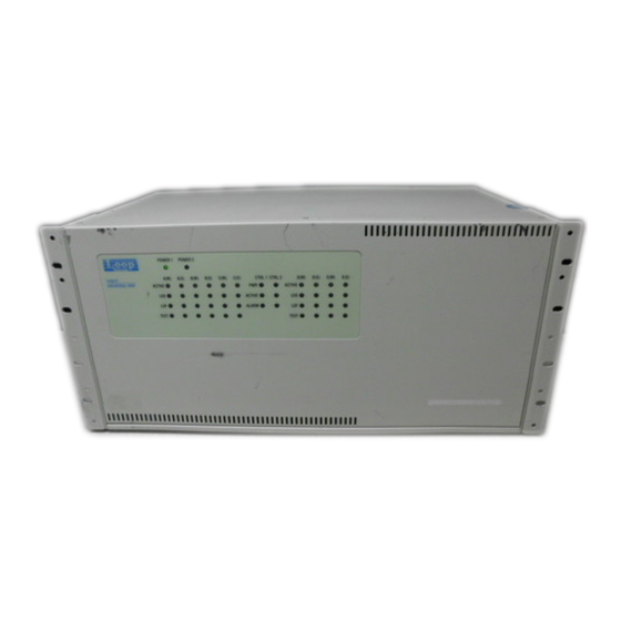
2.3.1.2 Rear View The Rear view of Loop-V 4100 is shown in the following figure. There are 17 slots for different plug-in cards. Slot positions on ports A(M), A(S), B(M), B(S), C(M) and C(S) are used to plug in DS3, E3, HD_E1 and HD_T1 cards. -
Page 13: Electrical Connections
The Loop-V 4100 is designed to allow for "hot plug-in" or “hot-swapping” of modules. This means that interface cards can be inserted and removed with the main chassis powered up. Onreplacement of a plug-in card, the previous configuration of the port will be used if the replaced card is of the same type. -
Page 14: Cpu Connection
Chapter 2 Installation 2.3.3 CPU Connection The Loop-V 4200-28 can support two CPU boards for redundancy. These two boards are placed in the slots, located in the rear of the chassis, marked “CR 1” and “CR 2”. When the system starts, one CPU board will automatically become the primary unit, and the other will become the redundant. -
Page 15: Connection
Chapter 2 Installation 2.5 Connection 2.5.1 Connectors The Loop-V 4100 has different connectors for the different ports: OC3/STM1, DS3, E3, HD_E1, HD_T1, Ethernet, and console. OC3/STM-1: SC, ST or FC-PC, BNC DS3: Ethernet: RJ45 Console: HD_E1 SCSI 68 HD_T1 SCSI 68 2.1.1... -
Page 16: Console Port Connector
2.5.3 Console Port Connector The console port is a DB9 configured as a DCE to mate with IBM compatible portable PC with DB9 communications port configured as DTE. Table 2- 3 DB9 Console Port (Loop-V 4100) Pin Number Signal Source... -
Page 17: Operation
Chapter 3 Operation 3 OPERATION This chapter describes the configuration options and operational functions. Refer to Chapter 5: Terminal Operation for detailed operational procedures of the main unit. Each module also has operational descriptions in their respective manuals. 3.1 Quick Start This quick start section is provided to give a brief overview so operation can begin immediately. -
Page 18: Date
3.5.3 Master Clock The Loop-V 4100 has a system clock Phase Lock Loop (PLL), which may be phase locked to the internal clock, an external clock, or the OC3/STM1 and High Density E1 card’s clock inputs. The external clock follows ITU G.703 specifications, which is either a 2.048 MHz or a 1.544 MHz AMI signal (external clock frequency specified on order). -
Page 19: Logon, Logoff And Password
3.7 Time Slot Interchange (Digital Access Cross-Connect) An important function of the Loop-V 4100 is Time Slot Interchange (TSI), also known as Digital Access Cross-connect System (DACS), where each DS0 time slot of any line can be assigned to any DS0 time slot of any line including itself. - Page 20 Original time slot order The Loop-V 4100 has four maps, each of which can be modified at any time. However, the "working map" needs to be selected through a command, and then that map will be the current, active map. When the "Store"...
-
Page 21: Alarms And Reports
3.8 Alarms and Reports For the HD_E1 plug-in card, the Loop-V 4100 has many types of alarms, as listed in Table 3-3 below. The Loop-V 4100 also has an alarm queue which records the latest 200 alarms with a time stamp. Alarm history and alarm status registers, which are used to track the alarm count, are also available. -
Page 22: Led Operation
Chapter 3 Operation 3.9 LED Operation The following table lists each LED and its color and indications. Each plug-in module has a rear panel LED, which matches the corresponding front panel LED. The rear panel LEDs are listed in the individual module’s User’s Manual. -
Page 23: Snmp Connection
Before SNMP is enabled, make sure the IP address for the Loop-V 4100 is configured correctly and the communication parameters match the Terminal server port. Once the SNMP agent is activated, the ping command can be used to verify the status of the Loop-V 4100. The command is as folows: $ ping 192.1.100.45... -
Page 24: Verifying Loop-V 4100 Operations
Especially during initial installation, excessive errors may be due to (a) incorrect configuration of either LOOP-V 4100 or of the equipment at the other end of the line, or (b) due to faulty line installation, which results in excessive noise, cross talk, or impedance mismatch. Especially in electrically noisy environments, such as central offices, the use of shielded cables is mandatory. -
Page 25: Loopback Block
Chapter 3 Operation 3.11.3 Loopback Block Figure 3-2, below, illustrates Loop-V 4100 loopbacks. Explanations of these loopbacks follow in the text below the diagram. OC3/STM1 Note: All loopback numbers on this diagram correspond directly to the numbered labels in HD_E1/T1 the list below. - Page 26 Chapter 3 Operation 13. E3 Payload Loopback: Takes all traffic except framing. 14. E3 Local Loopback: Takes all traffic from the back-plane and returns it to the back-plane. 15. E3 (Multiplex 16E1) Line Loopback: Takes traffic from the E3 framer (including E1/T1 framing) and returns it to the E3 framer.
-
Page 27: Firmware Download
2. Using Telnet or a VT-100 terminal to control the Loop-V 4100, begin the download process as outlined in Section 5.7.1. 3. When prompted by the Loop-V 4100, enter the IP address of the TFTP server and the file name of the firmware file. -
Page 28: Front Panel Operation
Chapter 5 Terminal Operation 4 FRONT PANEL OPERATION There are no front panel operations on the Loop-V 4100... -
Page 29: Terminal Operation
A VT100 type terminal can be connected to the console port, which is a standard RS232 interface. Using single-character commands and arrow keys, the LOOP-V 4100 can be configured and monitored. The single-character commands are not case sensitive. On each screen, the available commands and the configurable fields are highlighted. -
Page 30: Controller Configuration
Chapter 5 Terminal Operation 5.1 Controller Configuration Press “C” to view the Controller Configuration screen. V 4 1 00 = == Co n tr o ll e r C o nf i gu r at i on == = 1 6 :1 4 : 15 0 7 /2 5 /2 0 02 A - >... -
Page 31: Clock Source Setup
Chapter 5 Terminal Operation 5.1.2 Clock Source Setup Press “B” from the Controller Configuration screen to view the Clock Source Setup screen. V 4 1 00 = == Cl o ck S ou r ce Se t up == = 1 6 :1 4 : 27 0 7 /2 5 /2 0 02 M a s te r _C l k S ou r ce : C lo c k T yp e :... -
Page 32: Information Summary
Chapter 5 Terminal Operation 5.1.4 Current TSI Map Press “D” from the Controller Configuration screen to view the current TSI Map. V 4 1 00 = = = S ys t em Se t u p ( Cu r re n t M AP ) = = = 1 6 :1 5 : 39 0 7 /2 5 /2 0 02 A R R OW KE Y S: CU R SO R M O VE , T A B/ ` : R OL L UP / DO W N O PT I ON S D S 3_ T 1... -
Page 33: Alarm Queue Summary
Chapter 5 Terminal Operation Alarm Queue Summary Press “Q” from the Controller Menu to view the Alarm Queue Summary. Select the messages you wish to see and press “ENTER”. V 4 1 00 = = = A la r m Q u eu e S u mm a ry == = 1 6 :1 6 : 12 0 7 /2 5 /2 0 02 <... -
Page 34: Controller Setup
Chapter 5 Terminal Operation 5.4 Controller Setup Press “S” from the Controller Menu screen to view the Controller Setup screen. V 4 1 00 == = C o nt r o ll e r S et u p = == 1 6 :1 6 : 53 0 7 /2 5 /2 0 02 A - >... -
Page 35: Figure 5- 1 1:1 (Bidirection) Tsi Mapping
Chapter 5 Terminal Operation Please refer to the notes below for m ore information on TSI m apping. Note: TSI Mapping Two options are available for TSI mapping. The choices are 1:1 (Bidirection) or 1:N Multicast. As shown in Figure 5-1, below, 1:1 (Bidirection) TSI mapping is from a single port to a single port and signals flow in both directions. -
Page 36: Clock Source
Chapter 5 Terminal Operation 5.4.2 Clock Source Press “B” from the Controller Setup screen to access the Clock Source screen. V 4 1 00 = = = S ys t em S et u p ( CL O CK ) = = = 1 6 :1 7 : 20 0 7 /2 5 /2 0 02 A R R OW KE Y S: CU R SO R M O VE , T A B/ ` : R OL L UP / DO W N O PT I ON S M a s te r _C l k S ou r ce :... -
Page 37: Select A New Tsi Map
Chapter 5 Terminal Operation T o save maps to flash memory, use the V-command from the Controller Menu. T o activate a map as the current map, use the D-command from the next screen. V 4 1 00 = == Sy s te m Se t up (M A P) == = 1 6 :1 7 : 50 0 7 /2 5 /2 0 02 P l ea s e u se D- c om m an d ( n ex t s c r ee n ) t o a ct i ve ma p a s c u rr e n t ma p . -
Page 38: Copy A Tsi Map To Another
Chapter 5 Terminal Operation Press “Y” to confirm the setup for the new m ap, or “N” to return to the Controller Menu without saving, T o save maps to flash memory, use the V-command from the Controller Menu. V 4 1 00 == = S y st e m S e tu p ( N ew ma p ) = == 1 6 :1 7 : 55 0 7 /2 5 /2 0 02 A R R OW KE Y S: CU R SO R M O VE , T A B/ ` : R OL L UP / DO W N O PT I ON S... -
Page 39: Clear A Tsi Map
Chapter 5 Terminal Operation T hen press “Y” to confirm the setup. V 4 1 00 = = = S ys t em S et u p ( Co p y) == = 1 6 :1 8 : 04 0 7 /2 5 /2 0 02 A R R OW KE Y S: CU R SO R M O VE , T A B/ ` : R OL L UP / DO W N O PT I ON S C op y T S I M ap f ro m M A P_ 1 t o M A P_ 2 >... -
Page 40: Priority Setup
Chapter 5 Terminal Operation 5.4.7 Priority Setup Press “G” from the Controller Setup screen to access the Priority Setup screen. V 4 1 00 = = = P ri o r it y S e tu p = = = 1 6 :1 8 : 31 0 7 /2 5 /2 0 02 A R R OW KE Y S: CU R SO R M O VE , T A B/ ` : R OL L UP / DO W N O PT I ON S H I G H P RI O RI T Y : C O NS O LE... -
Page 41: System Password Setup
Chapter 5 Terminal Operation 5.5.1 System Password Setup Press “A” from the Password Setup screen to set up the s ystem password. V 4 1 00 = == Pa s sw o rd S et u p ( Sy s te m ) = == 1 6 :1 8 : 40 0 7 /2 5 /2 0 02 A R R OW KE Y S: CU R SO R M O VE , T A B/ ` : R OL L UP / DO W N O PT I ON S E n ab l e P as s wo r d : Y E S... -
Page 42: System Alarm Setup
Chapter 5 Terminal Operation 5.6 System Alarm Setup Press “M” from the Controller Menu screen to set up the System Alarm. V 4 1 00 = == Sy s te m Al a rm Se t up == = 1 6 :1 8 : 53 0 7 /2 5 /2 0 02 A R R OW KE Y S: CU R SO R M O VE , T A B/ ` : R OL L UP / DO W N O PT I ON S [ A l ar m A c ti o n] A L A RM... -
Page 43: Download Firmware
Chapter 5 Terminal Operation 5.7.1 Download Firmware Press “A” from the File Transfer menu to download firm ware. V 4 1 00 = == Do w nl o a d F ir m wa r e = == 1 6 :1 9 : 03 0 7 /2 5 /2 0 02 A R R OW KE Y S: CU R SO R M O VE , P l ea s e I np u t : n nn . -
Page 44: Upload Firmware
Chapter 5 Terminal Operation 5.7.2 Upload Firmware Press “B” from the File Transfer menu to upload firm ware. T he procedure for uploading firm ware is the same as the procedure for downloading firm ware. V 4 1 00 == = U p lo a d F i rm w ar e = = = 1 6 :2 6 : 18 0 7 /2 5 /2 0 02 A R R OW KE Y S: CU R SO R M O VE , T A B/ ` : R OL L UP / DO W N O PT I ON S F i r mw a re 1 V er s io n... -
Page 45: Upload Configuration
Chapter 5 Terminal Operation The following screen will appear as the download takes place. V 4 1 00 == = D o wn l oa d Co n fi g ur a ti o n = == 1 6 :3 9 : 27 0 7 /2 5 /2 0 02 A R R OW KE Y S: CU R SO R M O VE , B A CK S PA C E t o e d it , E S C t o a bo r t T F T P S er v er IP : 1 40 . - Page 46 Chapter 5 Terminal Operation The following screen will appear as the upload takes place. V 4 1 00 = = = U pl o ad C on f ig u ra t io n = = = 1 6 :3 8 : 01 0 7 /2 5 /2 0 02 A R R OW KE Y S: CU R SO R M O VE , B A CK S PA C E t o e d it , E S C t o a bo r t T F T P S er v er IP : 1 40 .
- Page 47 Chapter 5 Terminal Operation When the redundant board exists the following screen will show. It will ask “Are you sure?” Press “Y” to proceed with the firmware copying process. Press “N” to abort. V 4 1 00 = == C op y Fi rm w ar e to Re d un d an t B o ar d == = 1 6 :4 2 : 10 0 7 /2 5 /2 0 02 C u rr e nt Fi r mw a re Ba n k: 1 N e xt B oo t Fi r mw a re Ba n k: 2 C o py fi r mw a re to Re d un d an t B o ar d - a re yo u s u re ?
-
Page 48: Store / Retrieve Configuration
Chapter 5 Terminal Operation The following screen will appear as the copying takes place. V 4 1 00 = == C op y F i rm w ar e to Re d un d an t B o ar d == = 1 6 :4 2 : 10 0 7 /2 5 /2 0 02 C u rr e nt Fi r mw a re Ba n k: 1 N e xt B oo t Fi r mw a re Ba n k: 2 = = = >... -
Page 49: Store Configuration
Chapter 5 Terminal Operation 5.8.1 Store Configuration Press ENT ER from the above screen, for an action confirm ation. V 4 1 00 == = St o re / Re t ri e v e C on f ig u ra t io n == = 1 6 :4 6 : 49 0 7 /2 5 /2 0 02 >... -
Page 50: Alarm Cutoff
Chapter 5 Terminal Operation 5.8.3 Copy Unit Configuration (HD_E1 and HD_T1 only) Press “B” from the Controller Menu screen to copy the Unit Configuration. You must key in the source unit. This feature is available only for theHD_E1 card. V 4 1 00 == = U n i t C op y = = = 1 6 :4 7 : 16 0 7 /2 5 /2 0 02 P r e ss TA B k e y t o r ol l u n it , E N TE R t o ac c ep t , o r E SC ex i t... -
Page 51: Clear Alarm Queue
Chapter 5 Terminal Operation 5.10 Clear Alarm Queue Press “X” from the Controller Menu to clear the alarm queue. V 4 1 00 == = C o nt r o ll e r M en u = = = 1 6 :4 7 : 18 0 7 /2 5 /2 0 02 S e r ia l N u mb e r : 02 4 10 2 Co n ne c t P or t : S UP V _P O RT... -
Page 52: Load All Ports Default
Chapter 5 Terminal Operation A prompt will ask “Are you sure? (Y/N)? Key in “Y” to proceed or “N” to abort. V 4 1 00 = = = R es e t C o nt r ol Bo a rd == = 1 6 :4 7 : 38 0 7 /2 5 /2 0 02 >... -
Page 53: Controller Return To Default
Chapter 5 Terminal Operation 6. 2 Controller Return to Default Press “Y” from the Controller Menu screen to return to default. Then enter “Y” or “N” to confirm it. V 4 1 00 == = C o nt r o ll e r M en u = = = 1 6 :4 8 : 25 0 7 /2 5 /2 0 02 S e r ia l N u mb e r : 02 4 10 2... -
Page 54: Appendix A: Firmware Download Procedure
Chapter 6 Appendix A 6 Appendix A: Firmware Download Procedure Ethernet Network TFTP Server Loop-V 4100 CTRL1 Ethernet Port Telnet RJ45 Connecter Console Port Crossover UTP/ STP Cable Loop-V 4100 CTRL1 Ethernet Port RJ45 Connecter TFTP Server Console Port VT100... -
Page 55: Normal Download Procedure
If you are using a single PC setup as depicted in Figure 6-2, above, the PC is acting as a VT- 100 monitor as well as a TFTP server. Use a UTP/STP Crossover cable to connect the Ethernet Port of the Loop-V 4100 Controller Card to the Ethernet Port of the TFTP server. - Page 56 Chapter 6 Appendix A Click the TFTP server icon on your PC screen. A TFTP screen will appear showing your PC’s address. Left-click your mouse on the Settings button. The TFTP settings screen will appear as below. Select the file folder you wish to dowload to. In our example we chose C:/My Documents, but any file folder will do.
- Page 57 Chapter 6 Appendix A Right-click your mouse on the Network Neighborhood icon on your computer screen. A menu box will appear. Go to the bottom of the menu and left-click your mouse on Properties. The Network window will appear. Scroll down to TCP/IP and then left-click your mouse on the Properties button.
- Page 58 6-2 . Move to the top of the screen and left-click your mouse on the Gateway button. Key in a Gateway address. If you are using the Console Port of the Loop-V 4100 Controller Card to download. the Gateway address will be the IP address of the Loop-V 4100 Ethernet port.
- Page 59 Controller Menu will appear as shown below. If there is a single CPU (Controller Card) in the V 4100 unit the screen will indicate that the Redundant Controller is disabled. If the Loop-V 4100 is equiped with two CPUs the screen will indicate that the Redundant Controller is enabled. For demonstration purposes only, that area of the screen has been highlighted in the sample screen below.
- Page 60 Chapter 6 Appendix A Press “S” from the Controller Menu screen to access the Controller Setup screen. V4100 === Controller Setup === 14:05:16 04/18/2003 A -> System B -> Clock source C -> TSI map D -> Select a new TSI map E ->...
- Page 61 Chapter 6 Appendix A Press V from the Controller Menu to store. The Store/Retrieve Configuration screen will appear. Use the arrow k eys to m ove the cursor to “STORE” and press TAB to select it. The current selection will be highlighted by an asterisk (*). Then press ENT ER.
- Page 62 The following screen will appear. Key in the command and left-click OK with your mouse. The MS DOS Prompt screen will appear as follows. Key in ‘ping’ and the IP address of the Loop-V 4100 as shown on the sample screen below. Then press ENTER. The ping test results will appear on the screen.
- Page 63 The Loop-V 4100 we used in these sample screens has the current firm ware in BANK 1. Your Loop-V 4100 may have it in BANK 2. If that is the case, then all of the following descriptions you see will have BANK 1 and BANK 2...
- Page 64 Chapter 6 Appendix A Use the arrow k eys to move the cursor down to Firmware File Name. Then k ey in a file name and press ENTER. V 4 1 00 = = = D ow n lo a d F i rm w ar e = = = 17 : 19 : 5 0 07 / 19 / 20 0 0 A R R OW KE Y S: CU R SO R M O VE , B A CK S PA C E t o e d it , E S C t o a bo r t F i r mw a re 1 V er s io n...
- Page 65 BANK for backup. If a download fails and the user wishes to revert to the previous firmware, instructions for doing so can be found in Section 6.2 of this appendix. You must now reset the Loop-V 4100. When you do the firmware will switch from Bank 1 to Bank 2.
-
Page 66: Downloading To Dual Cpus
Chapter 6 Appendix A 6.1.1 Downloading to Dual CPUs The process for downloading to dual CPU’s is almost identical to the process of downloading to a single CPU. Some dlistinct differences do exist though. These differences and other points of importance are explained below Connections –all conections are identical to those used for single CPU downloads. - Page 67 Chapter 6 Appendix A You will be asked for your password. Key it in. Then press ENTER. V 4 1 00 = == C op y F i rm w ar e to Re d un d an t B o ar d == = 1 1 :0 5 : 34 0 4 /0 9 /2 0 03 C u rr e nt Fi r mw a re Ba n k: 1 N e xt B oo t Fi r mw a re Ba n k: 2 = = = >...
- Page 68 Chapter 6 Appendix A When you press Z from the Controller Menu to reset the primary Control Board, the following screen will show. Select Primary by putting the asterisk beside it. Remove the DB9 cable connector from the Console Port of Controller Card #1and plug it into the Console Portof Controller Card #2.
-
Page 69: Procedure For Reverting To The Previous Version Of Firmware
: v 10 4 .r u n << Press ESC key to abort, ENTER key to continue >> Pull out the CPU module from the Loop-V 4100 unit. Close the jumper 11 (JP11). The location of the jumper is illustrated in Figure 1 below. - Page 70 Chapter 6 Appendix A Plug- the CPU module into the Loop-V 4100 unit, then the Loop-V 4100 will reset. Press “L” from the Controller Menu screen to transfer files, as shown. V 4 1 00 = = = F il e Tr a ns f er == = 1 7 :1 9 : 46 0 7 /1 9 /2 0 00 A - >...
Need help?
Do you have a question about the Loop-V 4100 and is the answer not in the manual?
Questions and answers