Table of Contents
Advertisement
Quick Links
INSTALLATION
& OPERATION
MANUAL
IMPORT ANT:
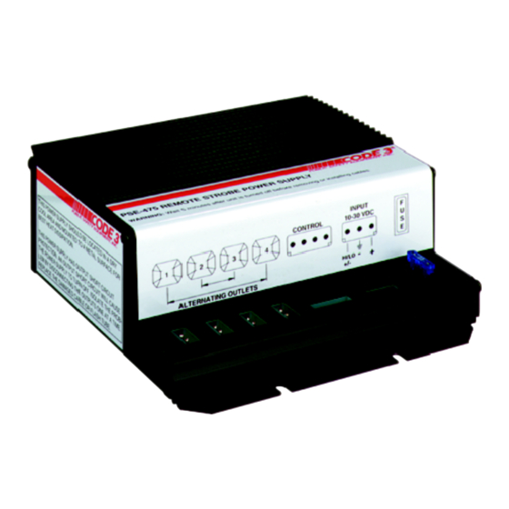
PSE440
REMOTE STROBE
POWER SUPPLY
Contents:
Introduction ......................................................... 2
Standard Features .............................................. 2
Specifications ..................................................... 2
Unpackaging & Pre-installation .......................... 3
Installation & Mounting ....................................... 4
Wiring Instructions ......................................... 4-10
Flash Control Options ......................................... 7
Switching Control Variations ........................... 7-9
Maintenance ..................................................... 11
Troubleshooting ................................................ 11
Warranty ........................................................... 12
Read all instructions and warnings before installing and using.
INSTALLER:
This manual must be delivered to the end user of this equipment.
TM
PSE440
REMOTE STROBE
POWER SUPPLY
Advertisement
Table of Contents

Summary of Contents for Code 3 PSE440
-
Page 1: Table Of Contents
INSTALLATION & OPERATION MANUAL PSE440 REMOTE STROBE POWER SUPPLY PSE440 REMOTE STROBE POWER SUPPLY Contents: Introduction ............2 Standard Features ..........2 Specifications ............. 2 Unpackaging & Pre-installation ......3 Installation & Mounting ........4 Wiring Instructions ......... 4-10 Flash Control Options ......... 7 Switching Control Variations ...... -
Page 2: Introduction
The latest in MOSFET technology and advanced design provide efficient operation, meaning superior performance, reliability and long life. The use of intelligent microprocessor control allows the model PSE440 to offer more light pattern options and versatility than any other remote system available. The user may select the standard Quad Flash pattern or any of the auxiliary patterns. -
Page 3: Unpackaging & Pre-Installation
The use of this or any warning device does not insure that all drivers can or will observe or react to an emergency warning signal. Never take the right-of-way for granted. It is your responsibility to be sure you can proceed safely before entering an intersection, driving against traffic, responding at a high rate of speed, or walking on or around traffic lanes. -
Page 4: Installation & Mounting
1. Install the remote strobe light heads in the preferred locations and route the three wire cable from the remote strobe heads to the PSE440 power supply. Leave enough cable at the power supply so that the cables are not strained when connected to the power supply. Follow the installation instructions for the... - Page 5 2. After the cables have been properly routed for each strobe head they will have to be terminated with the three pin AMP socket housings provided. The cables are factory terminated with the proper AMP pins for insertion into the housings, see Figure 3. If there is a need to re-terminate any wires, Figure 3 also includes stripping and crimping information.
- Page 6 FLASH CONTROL HARNESS ASSEMBLY The Flash Control wire harness is to be connected to the 4 position socket connector on the PSE440 strobe power supply. (See Figure 3 on page 5). The Flash Control harness consists of an AMP 4 pin connector with 4 wires : white, orange , yellow and brown.
-
Page 7: Flash Control Options
TABLE 1 - FLASH MODE SELECTION Switching Control Variations The Model PSE440 strobe outlet flashing sequence variations are controlled by four factors: 1. Selecting one or more of the Flash Modes available, see Table 1. 2. Determining the user supplied switching necessary to control these modes. - Page 8 FIGURE 6 - Switching Controls and Strobe Light Outlet Functions The following diagrams show some of the wiring configurations possible for various flash modes. All fuses shown are to be customer supplied, and recommended fuse ratings to be observed. All switches are to be customer supplied.
- Page 9 SELECTIVE SWITCHING OF OUTLETS 1 AND 4 (only) OUTLETS 2 AND 3 (only) IN HIGH POWER The following switching variations show selection of various optional patterns: STANDARD DOUBLE FLASH MODE CYCLE FLASH MODE 4 OUTLETS ON-OFF SWITCHING 4 OUTLETS ON-OFF SWITCHING HIGH POWER HIGH POWER...
- Page 10 4 OUTLETS ON-OFF-ON HIGH POWER LOW CURRENT SWITCHING CONTROL The PSE440 Power Supply utilizes low current switching. This means, if desired, the power in (RED) connection can be connected directly to the source (+), and the control connections can be used to switch the strobe supply on or off using a low current source (+).
-
Page 11: Maintenance
Maintenance The PSE440 Remote Strobe Power Supply has been designed to provide trouble free service. In case of difficulty , refer to the Troubleshooting section. Periodic inspection of power supply wiring, and strobe light head connections for shorted or open wires will assure trouble free operation. The primary cause of short circuits has been found to be wires passing through firewalls, roofs, etc. -
Page 12: Warranty
*Code 3 reserves the right to repair or replace product at its discretion and assumes no responsibility or liability for expenses incurred for the removal and/or reinstallation of products requiring service and/or repair.
Need help?
Do you have a question about the PSE440 and is the answer not in the manual?
Questions and answers