
Related Manuals for Howden ENF

Summary of Contents for Howden ENF
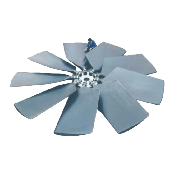
- Page 1 Service Manual Installation and Maintenance E-series Axial Flow Cooling Fans Warning Failure to comply with these instructions could cause serious bodily harm or property damage and will void the warranty. Howden 24-07.030r04E 1/25...
-
Page 2: Table Of Contents
Retaining plate ..........................15 Balancing ............................16 IV. Commissioning ..........................16 V. Preventive Maintenance ......................18 VI. Contact Howden ......................... 19 VII. Trouble Shooting ........................20 VIII. Overview Tightening Torques ....................23 IX. Hardware Overview ........................24 X. Guideline for acceptable vibration levels of cooling fans in application category BV-3 (according ISO 14694) ........................ -
Page 3: General Information
(As well depends on duty point) Howden E-series fans are most widely used ft/min and are available in three different blade pro- 13780 files, ENF, ELF & ELFA. Whether you are 11811 looking for a highly efficient impeller and/or a ELFA 9055... -
Page 4: Receiving / Handling / Storage / Disposal
FAN 30ENF6 EP Leading edge protection for wet cooling tower applications Number of blades: 3,4,5,6,7,8,9 Impeller type: ENF, ELF, ELFA Fan diameter: metric or imperial (>100 = mm, <100 = feet) Another example: FAN 8910ELF8... -
Page 5: Receiving And Unloading
Order number of the Customer and of Howden. Impeller type (fan identification code) Parts supplied by Howden. The delivered goods shall be checked upon Figure 2 arrival for full compliance with the order The fan blades can be lifted from the packing and/or the parts count and description stated by placing a single sling around the blade. -
Page 6: De-Commissioning
The inert nature of the materials used will prevent chemical pollution of soil and ground water in case of in land-fill. Howden 24-07.030r04 6/25 E-series Axial Flow Cooling Fans... -
Page 7: Exploded View And Part List
Polyurethane coated steel 1 (optional) Central bolt M16 or M20 or M24 Steel class 8.8 electro-galvanised 1 (optional) Washer Electro-galvanised 1 (optional) Gasket Rubber 1 (optional) 1 (optional) Not supplied by Howden Table 2 Howden 24-07.030r04 7/25 E-series Axial Flow Cooling Fans... -
Page 8: Installation
Check the concentricity of the driver shaft end before mounting the impeller. The im- peller should not be mounted if the con- centricity error exceeds 0.02 mm (0.0008”) see figure 6. Flow Figure 6 Figure 5 Howden 24-07.030r04 8/25 E-series Axial Flow Cooling Fans... -
Page 9: Coupling Flange With Parallel Bore
Tighten the bolts to the torque shown in (15). Supply of retaining plate items 14, table 3. Do not over-torque. Excessive 15, 16 and 17 by Howden is optional. torque can cause coupling flange or Item 19 (key) is not supplied by Howden. -
Page 10: Hub-Plate Installation
(17) and secure it to the shaft with the lock washer (16) and the central bolt (15). Supply of retaining plate items 14, 15 and 16 by Howden is optional. For torque values of the retaining plate bolts see table 7 on page 22. - Page 11 9 ft., Figure 11 than please ask Howden at order placement. Important Tip: You may also choose to install the fan blades onto the hub-plate before bolting the Impellers with a diameter smaller than complete impeller onto the coupling flange.
-
Page 12: Blades Installation
When the blades are hanging un- Note: For impellers > 4455 mm / 14 feet the derneath the hub-plate we recommend in- blade sets can be installed on any position of Howden 24-07.030r04 12/25 E-series Axial Flow Cooling Fans... - Page 13 (at least as long as the profile width) on top of the blade (discharge side) at about 50 mm (2 inches) from the blade profile end. Place an inclinometer on top of the straight edge (figure 15). Figure 15 Howden 24-07.030r04 13/25 E-series Axial Flow Cooling Fans...
-
Page 14: Minimum Tip-Clearance
Figure 17 When the blade angle has changed, the U- Howden recommends a tip clearance of 0.5% of bolts need to be tightened again to full the impeller diameter. Fan selections using torque and also re-tightened after 120-150 Howden CF-P20 software use this default stan- hours. -
Page 15: Impeller Diameter Reduction
(see table 4 for the number of recom- Important mended measuring points). Slowly rotate Howden strongly recommends the the impeller by hand to the different meas- installation of a retaining plate for all uring points. -
Page 16: Balancing
If the impeller is installed in a different hub- plate configuration than it was balanced, e.g. configuration B for an installation with the clamping pieces at flow inlet side, you run the risk of an unquiet operation. Howden 24-07.030r04 16/25 E-series Axial Flow Cooling Fans... - Page 17 Immediately after first start up check for 19, in case the fan is mounted directly on smooth operation of the fan assembly. the gearbox shaft. Check for irregular noise / vibrations. Howden adopts the guideline given in standard ISO-14694 describing acceptable vibration levels. The “in situ”...
-
Page 18: Preventive Maintenance
Directive material (PU filler, e.g. Sikaflex 252) to 94/9/EC (ATEX 100): prevent moisture penetration affecting the blades. Howden Cooling Fans can Electrically earthed metal bearing provide you a repair kit complete with in- support to avoid sparkling by electrical structions. -
Page 19: Contact Howden
Howden shall be glad to ad- vise you the best maintenance solution for your application. Replace corroded bolts and nuts. -
Page 20: Trouble Shooting
Service Manual VII. TROUBLE SHOOTING In case of any failure, please contact Howden stating the impeller order number as mentioned on the nameplate located at the hub of the impeller. Problem Possible cause Possible solution Air volume low. Fouling of system. - Page 21 Blade is not flush against Release U-bolts, pull the lower clamping piece. blade outwards and re- tighten the U-bolts to the correct torque. Blade angle(s) not within Re-set the blade angles. ±0.5° tolerance. Howden 24-07.030r04 21/25 E-series Axial Flow Cooling Fans...
- Page 22 We advise to fill these ages. cracks with a touch-up material e.g. Sikaflex 252 to prevent moisture pene- tration affecting the blades (Contact Howden for a re- pair kit). Hairline cracks on blade Could appear in resin rich Hairline cracks are harm- surface.
-
Page 23: Overview Tightening Torques
Torque values for retaining plate bolt Class 8.8 / A4 Retaining plate Thread [mm] / [inch] Size 79 mm / 3.11“ 189 mm / 7.44” 240 mm / 9.45” 360 mm / 14.17” M30 Table 7 Howden 24-07.030r04 23/25 E-series Axial Flow Cooling Fans... -
Page 24: Hardware Overview
3048 3120 3353 3515 3658 3962 4267 4455 4877 4950 5486 5545 6096 6240 6702 7030 7315 7920 7925 8535 8910 9145 9754 9900 10000 10400 10973 11100 12192 12400 Table 8 Howden 24-07.030r04 24/25 E-series Axial Flow Cooling Fans... -
Page 25: Guideline For Acceptable Vibration Levels Of Cooling Fans In Application Category Bv-3 (According Iso 14694)
Fit information added at installation instructions of parallel bore coupling flanges Adjustment of blade assembly procedure regarding re- tightening after blade angle adjustment Adjustment of instructions coupling flange with tapered bushing Replacement of the word cap screws into bolts Howden 24-07.030r04 25/25 E-series Axial Flow Cooling Fans... - Page 26 IX. Maximum Vibration Levels For Balance Vibration category BV-3 (ISO 14694) & added Table 9 Changed material codes: AISI 304 AISI 316 Inserted „‟Blades Installation‟‟ „‟Procedure b‟‟, p13 Inserted „‟ IV Commisioning‟‟ „‟Section G‟‟ p17 Howden 24-07.030r04 26/25 E-series Axial Flow Cooling Fans...
- Page 27 Hubplate installation important block E-series Blades installation part1 E-series Blades installation part2 E,SX-series Blades installation part3 r2 Blades installation warning block r1 Minimum tip clearance Minimum tip clearance table E,SX-series Impeller diameter reduction Howden 24-07.030r04 27/25 E-series Axial Flow Cooling Fans...
- Page 28 Commissioning table D,SX,E-series r1 Commissioning important block Commissioning warning block2 Preventive maintenance Preventive maintenance important block Contact Howden Trouble shooting r1 Trouble shooting table1 r2 Overview tightening torques table1 E-series r1 Overview tightening torques table2 E-series r1 Hardware overview E-series...
Need help?
Do you have a question about the ENF and is the answer not in the manual?
Questions and answers