Table of Contents
Advertisement
Available languages
Available languages
Quick Links
BEFORE YOU START
BEFORE INSTALLING PUMP, BE SURE TO READ
THIS OWNER'S MANUAL CAREFULLY.
REFER TO PRODUCT DATA PLATE(S) FOR
ADDITIONAL OPERATING INSTRUCTIONS AND
SPECIFICATIONS.
C A U T I O N
Hazardous voltage.
• Keep work area clean, well-lit and uncluttered.
Can shock, burn, or
cause death.
• Keep safety labels clean and in good condition.
• Replace missing or damaged safety labels.
Ground pump before
connecting to power
• Wear safety glasses while installing or performing
supply. Disconnect
maintenance on pump.
power before working
• Adhere to the guidelines of the National Electric Code
on pump, motor
(NEC) or Canadian Electric Code (CEC), and any other
or tank.
state and local codes for ALL electrical installations.
Check with the appropriate agencies or contact a
licensed electrician.
Most water system problems result from improper
installation. It is suggested that you read this
manual carefully before installing your pump. The
"TROUBLESHOOTING SECTION" will assist you in
locating and eliminating the cause of any trouble you
may encounter after installation. Check and make
available all the tools you will need to install your pump.
Required tools may include wrenches, pipe sealant,
pipe fi ttings and nipples, screwdriver, etc.
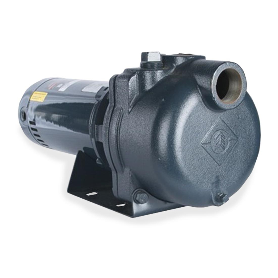
Self Priming Sprinkler Pump
OWNER'S MANUAL
Be sure to have available proper and adequate wiring
material to complete the installation correctly.
READ AND FOLLOW SAFETY INSTRUCTIONS
This is the safety alert symbol. When you see this
symbol on your pump or in this manual, look for
one of the following signal words and be alert to the
potential for personal injury:
D A N G E R
serious personal injury, death or major property damage
if ignored.
W A R N I N G
serious personal injury, death or major property damage
if ignored.
C A U T I O N
cause minor personal injury or major property damage if
ignored.
NOTICE indicates special instructions, which are
important but not related to hazards.
Carefully read and follow all safety instructions in
this manual and on pump.
Hazardous voltage.
WA R N I N G
Can shock, burn, or
cause death.
Ground pump before
connecting to power
supply. Disconnect
power before working
on pump, motor
or tank.
W A R N I N G
pump against closed discharge. Release all system
pressure before working on any component.
C A U T I O N
water before starting or pump will be damaged.
The motor on this pump is guaranteed by the
manufacturer and in event of failure it must be returned
to an authorized service station for repairs. Motor
warranty is void if repairs aren't made by an authorized
repair station.
warns about hazards that
warns about hazards that can cause
warns about hazards that will or can
WA R N I N G
HAZARDOUS PRESSURE
HAZARDOUS PRESSURE: Do not run
Do not run pump dry. Fill pump with
will
cause
1
Advertisement
Table of Contents

Subscribe to Our Youtube Channel
Summary of Contents for Franklin Electric TurfBoss
- Page 1 Self Priming Sprinkler Pump OWNER'S MANUAL Be sure to have available proper and adequate wiring material to complete the installation correctly. READ AND FOLLOW SAFETY INSTRUCTIONS This is the safety alert symbol. When you see this symbol on your pump or in this manual, look for one of the following signal words and be alert to the potential for personal injury: D A N G E R...
-
Page 3: Electrical Safety
ELECTRICAL SAFETY INTRODUCTION C A U T I O N You have purchased one of the most user friendly Make sure all ELECTRICAL POWER IS pumps available. The Turf Boss pumps are made with OFF before connecting any electrical wires. high quality materials which are designed to provide W A R N I N G Capacitor voltage may be hazardous. -
Page 4: Installation Tips
frost line, either bury the wellhead or use a PITLESS INSTALLATION TIpS ADAPTER that leaves the wellhead exposed for • Wrap all threaded male pipe ends and fittings with servicing while providing sealed openings in the well PTFE tape. This will ensure a good seal around all casing below the frost line. - Page 5 diameter to reduce friction loss. The friction loss in a system increases: 1.) As the flow rate increases 2.) As the piping size decreases Consult included Turf Boss performance tables (Appendix III) and friction loss tables (Appendix IV) to determine the amount of head lost for a given application.
- Page 6 Figure 5 B. Discharge port Connections (Figure 5) Step 1: PRIMING PORT Thread male adapter or pipe nipple into discharge port on top of pump. (Use PTFE tape on thread) 1-1/2" DISCHARGE PORT Step 2: 1-1/2" SUCTION PORT Connect pipe between the sprinkler manifold and the pump discharge.
-
Page 7: Installation Records
INSTALLATION RECORDS NOTICE: If you purchased a 3 phase pump/motor assembly, the motor rotation must be checked after To keep an accurate record of your installation, be priming the pump, but before continuous operation. sure to fi ll out the data below: Check the rotation by “bumping”... -
Page 8: Maintenance
Step 2: Step 1: Open discharge valves and any hoses on Remove motor access cover at back of motor. discharge side of pump. Step 2: Step 3: Feed the grounding wire (green or bare copper) Fill pump with water through the priming port on through the electrical conduit port in the side of the top of pump. - Page 9 C. pump Assembly Figure 8 Priming Port Reassemble unit by first pressing the ceramic seal into the seal plate. Use rubbing alcohol as a lubricant. Do not use an oil, vaseline or grease as this will damage the sealing surfaces of the shaft seal during operation. Next, install the motor bracket onto the motor using the four bolts.
- Page 10 PARTS FOR TURF BOSS SELF-PRIMING SPRINKLER PUMP AppENDIX I 1 1I 9F,G 8E,G 6E,G 4C,G 7E,G 3C,G Repair Part Order Codes by Model Number Figure Kit Grouping Description Number Identifier* TB1CI TB15CI TB2CI Plug Kits 305390901 Pump Case 305391901 305392901 Grommet 305396901 305396902...
-
Page 11: Appendix Ii - Troubleshooting
AppENDIX II - TROUBLESHOOTING Problem Possible Cause Remedy Pump does not deliver 1. The pump is is not full of water. 1. Stop the pump, fill it with water, check all pipe water or pressure connections to make sure there are no air leaks and try again. -
Page 12: Appendix Iii - Performance Curve
AppENDIX III - pERFORMANCE CURVE 2 HP 1.5 HP 1 HP M PH... -
Page 13: Appendix Iv - Friction Loss Tables
AppENDIX IV - FRICTION LOSS TABLES 1” 1¼” Schedule 40 pipe 1.049 in. i.d. / Type L Copper tube 1.025 in. i.d. Schedule 40 pipe 1.380 in. i.d. / Type L Copper tube 1.265 in. i.d. Friction Loss Friction Loss Ft Hd./ Ft Hd./ Ft Hd./100’... -
Page 14: Limited Warranty
THIS WARRANTY SETS FORTH THE COMPANY’S SOLE OBLIGATION AND PURCHASER’S EXCLUSIVE REMEDY FOR DEFECTIVE PRODUCT. Franklin Electric Company, Inc. and its subsidiaries (hereafter “the Company”) warrants that the products accompanied by this warranty are free from defects in material or workmanship of the Company. -
Page 15: Manual Del Propietario
Bomba para regadores autocebante MANUAL DEL PROPIETARIO Cerciórese de tener a disposición material adequado y apropiado para el cableado para concluir la instalación correctamente. LEA Y SIGA LAS INSTRUCCIONES DE SEGURIDAD Éste es un símbolo de alerta de seguridad. Cuando usted vea este símbolo en su bomba o en este manual, busque una de las palabras siguientes y esté... -
Page 17: Seguridad General
CUIDADO Usted ha comprado una de las bombas de manejo Cerciórese que todas las FUENTES más amigable que existen. Las bombas TurfBoss se ELÉCTRICAS ESTÉN APAGADAS antes de conectar fabrican con materiales de alta calidad diseñados para cualquier cable eléctrico. -
Page 18: Instalación
VERIFICACIÓN ANTES DE LA INSTALACIÓN • OPCIÓN DE INSTALACIÓN DE BOMBA EXTERNA: Cuando se instale fuera de la casa, la bomba se debe • La bomba no debe de estar a más de 25 pies sobre proteger con un alojamiento con calor auxiliar para la superficie del agua. - Page 19 TUBERÍAS puntos de Múltiples pozos llanos (Figura 2) La configuración pozo llano de múltiples puntos Atornillar la bomba a una base nivelada y sólida, si es consiste en dos o tres pozos como fuente de agua. posible. Ubicar la bomba con el bocal de succión de Los pozos deben estar por lo menos a cinco pies de frente para el(los) caño(s) de la fuente de agua.
- Page 20 A. Conexión del Bocal de Succión (Figura 4) B. Conexiones del Bocal de Salida (Figura 5) Etapa 1: Etapa 1: Conectar la válvula de pedestal o el punto del pozo Enroscar el adaptador macho o el niple del tubo al a la tubería y bajar el tubo y la válvula de pedestal bocal de salida de la parte superior de la bomba.
-
Page 21: Instalación Eléctrica
REGISTROS DE LA INSTALACIÓN funcionamiento continuo. Verifi que la rotación conectando y desconectando la corriente eléctrica al Para mantener un registro adecuado de su motor y observe la rotación del acoplamiento. Invierta instalación, cerciorarse de llenar los datos siguientes: la rotación como se indica en el motor si no coincide la fl echa de rotación en la estructura. - Page 22 Etapa 2: Etapa 1: Abrir las válvulas de salida y todas las mangueras Sacar la tapa de acceso al motor en la parte de del lado de salida de la bomba. atrás. Etapa 3: Etapa 2: Llenar la bomba con agua por el bocal de cebado Pasar el cable de tierra (verde o de cobre sin en la parte superior de la bomba.
- Page 23 agarrando el diámetro externo de la turbina con un A. Drenaje (Figura 8) guante y girándola en el sentido de las agujas del La bomba debe drenarse si corre el riesgo de reloj. Esto dejará la junta mecánica del eje a la vista. congelarse, si estuvo fuera de servicio durante un Esta junta se puede sacar del eje del motor para largo período de tiempo o si requiere manutención.
- Page 24 PIEZAS PARA LA TURF BOSS BOMBA AUTOCEBANTE PARA REGADORES ApÉNDICE I 9F,G 8E,G 6E,G 1Amp. 4C,G 7E,G 3C,G Códigos de Pedido de Repuestos por Número de Modelo Figura Identificador de Descripción Número Agrupamientode Kit* TB1CI TB15CI TB2CI Kits de tapones 305390901 Caja de la bomba 305391901...
-
Page 25: Apéndice Ii - Solución De Problemas
ApÉNDICE II - SOLUCIÓN DE pROBLEMAS Problem Causa Solución La bomba no expele agua 1. La bomba no está llena de agua. 1. Parar la bomba, llenarla de agua, verificar las conexiones de la tubería para asegurarse que no haya o presión pérdidas de aire e intentar nuevamente. - Page 26 ApÉNDICE III - CURVA DE DESEMpEÑO 2 HP 1.5 HP 1 HP l./seg. M PH...
- Page 27 ApÉNDICE IV - TABLAS DE pÉRDIDA DE FRICCIÓN 1” 1¼” Programar 40 tubos 1.049 pulgadas de diámetro interno/tubo de Programar 40 tubos 1.380 pulgadas de diámetro interno/tubo de cobre de 1.025 pulgadas de diámetro interno tipo L cobre de 1.265 pulgadas de diámetro interno tipo L Pérdida de fricción Ft Hd./ Pérdida de fricción...
- Page 28 CORRESPONDE EXCLUSIVAMENTE AL COMPRADOR EN CASO DE QUE EL PRODUCTO SEA DEFECTUOSO. Franklin Electric Company, Inc. y sus subsidiarias (en adelante “la Compañía”) garantiza que los productos que cubre esta garantía carecen de defectos en cuanto al material o la mano de obra de la Compañía.
-
Page 29: Avant De Commencer
Pompe d’arrosage auto-amorçante GUIDE D’UTILISATION Assurez-vous d’avoir sous la main le matériel d’installation électrique approprié pour terminer l’installation correctement. LISEZ ET RESpECTEZ LES CONSIGNES DE SÉCURITÉ Voici le symbole d’avertissement en matière de sécurité. Chaque fois que vous voyez ce symbole sur votre pompe ou dans le guide présent, vous trouverez un des trois mots-indicateurs suivants qui vous permettront de rester à... -
Page 31: Sécurité Générale
ÉLECTRICITÉ ET SÉCURITÉ INTRODUCTION Vous avez acheté une des pompes les plus faciles à AVERTISSEMENT Assurez-vous que TOUTE utiliser offertes sur le marché. Les pompes Turf Boss L’ALIMENTATION ÉLECTRIQUE EST COUPÉE avant de sont faites de matériaux de qualité et conçues pour brancher des fi ls électriques. -
Page 32: Installation
INSpECTION AVANT INSTALLATION • OPTION D’INSTALLATION À L’EXTÉRIEUR : Si vous installez la pompe à l’extérieur, elle doit être • La pompe ne doit pas être installée à une hauteur de protégée contre le gel par un abri de pompe pourvu plus de 8 m ( 25 pi ) au-dessus du niveau de l’eau. - Page 33 TUYAUTERIE Réseau de pointes filtrantes ( illustration 2 ) Si possible, boulonnez la pompe sur une base égale Dans une configuration de réseau de pointes et solide. Positionnez la pompe de façon à ce que filtrantes, l’eau provient d’au moins deux puits le l’orifice d’aspiration se trouve face aux conduites différents.
- Page 34 A. Raccord de l’orifice d’aspiration ( illustration 4 ) B. Raccords de sortie ( illustration 5 ) Étape 1 : Étape 1 : Raccordez le clapet de pied ou la pointe filtrante Vissez l’adaptateur mâle ou le mamelon dans la sortie au système de conduites et descendez la conduite sur le dessus de la pompe.
-
Page 35: Installation Électrique
FICHE D’INSTALLATION aucun autre appareil. • La pompe ne doit pas être mise en marche sans Afi n de conserver les renseignements exacts sur mise à la terre. l’installation, veuillez inscrire les informations REMARQUE : Si vous avez acheté un ensemble indiquées ci-dessous : pompe/moteur 3 phases, la rotation du moteur doit Date de l’installation :... - Page 36 Illustration 7 Câblage REMARQUE : Consultez les instructions de câblage sur le couvre-bornes ou la plaque signalétique du moteur. Voici les caractéristiques essentielles du moteur de la pompe : ORIFICE DE SORTIE DE 1,5 PO 1. ) 3450 T/M 2. ) Monophasé ORIFICE D'ASPIRATION DE 1,5 PO 3.
- Page 37 pRESSION dangereuse ! de moteur en saisissant le DE du rotor avec une main - Il ne faut pas faire fonctionner une gantée et en faisant tourner dans le sens inverse des pompe contre une sortie d’eau aiguilles d’une montre. Cela permettra de voir le joint fermée.
- Page 38 PIÈCES POUR POMPE D’ARROSAGE AUTO-AMORÇANTE DE TURF BOSS ANNEXE I 9F,G 8E,G 6E,G 4C,G 7E,G 3C,G Numéros de commande des pièces de rechange par nº de Nº Identificateur modèle Description d’illustration d’ensemble* TB1CI TB15CI TB2CI Ensembles de bouchons 305390901 Corps de pompe 305391901 305392901 Oeillet...
-
Page 39: Annexe Ii : Dépannage
ANNEXE II : DÉpANNAGE Problem Possible Cause Remedy Le débit d’eau en 1. La pompe n’est pas entièrement remplie d’eau. 1. Arrêtez la pompe, remplissez-la d’eau, provenance de la pompe assurez-vous de l’absence d’entrées d’air en est insuffisant ou nul vérifiant tous les raccords de la tuyauterie et essayez de nouveau. - Page 40 ANNEXE III - COURBE DE RENDEMENT 2 HP 1.5 HP 1 HP M PH...
- Page 41 ANNEXE IV - TABLEAUX DES pERTES DE CHARGE 1” 1¼” Tuyau série 40 1,049 po D. int. / tube en cuivre de type L 1,025 po D. Tuyau série 40 1,380 po D. int. / tube en cuivre de type L 1,265 po D. int.
- Page 42 NOTES • NOTES • NOTAS...
- Page 43 NOTES • NOTES • NOTAS...
- Page 44 CE QUI A TRAIT À UN PRODUIT DÉFECTUEUX. Franklin Electric Company, Inc. et ses filiales (ci-après « la Société ») garantissent que les produits accompagnés de la présente garantie sont exempts de défauts de matériel et de main-d’œuvre liés à la Société.
Need help?
Do you have a question about the TurfBoss and is the answer not in the manual?
Questions and answers