Table of Contents
Advertisement
Advertisement
Table of Contents

Summary of Contents for Eurocal SENATOR
- Page 1 SENATOR COUNTRYMAN System- Boilers Installation & Users Guide...
-
Page 2: Table Of Contents
- PLASTIC PIPE - CAPACITIES OF EXPANSION VESSEL - EXPANSION VESSEL SIZING - WARNING SEALED SYSTEM - FILLING SYSTEM - SENATOR CONVENTIONAL FLUE INSTALLATION - BALANCED FLUE INSTALLATION (INTERNAL) 13-21 - CONNECTING OIL SUPPLY 21-22 - ELECTRICAL CONNECTION (INTERNAL & EXTERNAL) -
Page 3: Warranty
INTRODUCTION Thank you for choosing the INTERNAL or EXTERNAL COUNTRYMAN COMBI oil boiler please read the following carefully. To the installer This manual must be left with the householder by the installer who will instruct the user on the boiler operation. To the user Please read the user section of this manual to familiarize yourself with the boiler operation. -
Page 4: User Instructions
USER INSTRUCTIONS Boiler Control Thermostat BOILER OPERATION The Boiler Control Thermostat responds to the temperature of the water within the boiler and switches power to the burner when heat is required. The burner has an independent control system which regulates the firing and (shut-off) of the burner. -
Page 5: Boiler Controls
BOILER CONTROLS BOILER CONTROL THERMOSTAT The temperature of the water within the boiler is controlled and maintained by the Boiler Control Thermostat located on the boiler control panel. TEMPERATURE SETTINGS: The Boiler Control Thermostat has a range of 50˚C to 80˚C. The recommended setting for the boiler control thermostat is: WINTER Heating and hot water supply 80˚C... -
Page 6: Switching The Boiler Off
SWITCHING THE BOILER OFF The boiler can be turned off by turning the rocker switch, located on the underside of control panel, to the OFF position. PLEASE NOTE: For longer periods of shutdown e.g. While away on holiday, switch OFF the mains (electrical supply) and turn OFF the OIL supply. -
Page 7: Restart
RESTART - Check there is adequate oil in the storage tank. - Check oil supply valves are open. - Switch on heating system (e.g. Time clock). - Depress the red Burner Reset Button on the burner Control Box, which will be illuminated. Both Burner Reset Button (illuminated) and the lockout Indicator on the Control Panel will go out and the burner will commence the ignition start sequence. -
Page 8: Regulations
REGULATIONS The installation of oil fired boilers should comply with the following standards and codes of practice. - BS5449 Forced circulation hot water heating systems for domestic use - BS5410-Part1 Oil installations up to 45kw. - BS7593 Water treatment of hot water central heating systems. - BS7671 Electrical Regulations. -
Page 9: Boiler Location
BOILER LOCATION Sound levels should be discussed with the householder, as some people may be sensitive to low noise levels in a small room, as it may appear more annoying than in a larger room. Please Note installation should take into account of flue position (see diagram). RECOMMENDED FLUE POSITION Please Note where the terminal is within 1 metre of any plastic material, such material should be protected from the effects of the combustion products of the fuel. -
Page 10: Service Requirements
INSTALLATION SERVICE REQUIREMENTS The boilers are serviced though an access panel at the front. A service access space of least 700mm should be made available at the front of the boiler. THE HEARTH The temperature of the surface below the boiler is less than 85˚C. If the floor under the boiler is of combustible material, then protection such as steel should be fitted between the boiler and the floor. -
Page 11: Preformed Pipe Work
PREFORMED PIPE WORK - 1 Of 22 mm section label Heating Flow - 1 Of 22 mm section label Heat Return - 1 Of 15 mm section label Cold Mains - 1 Of 15 mm section label Over Flow Preformed pipes, on the Internal system exit on the right hand side of the boiler. from the front view of the boiler. -
Page 12: Capacities Of Expansion Vessel
CAPACITIES OF EXPANSION VESSELS EXPANSION VESSEL SIZING Bs7074:Part1:1989 gives full details of accurate Safety Valve Setting @ method of calculating the required expansion Vessel charge and vessel capacity, assuming that full and accurate Initial System Pressure design information is available, particularly total (BAR GAUGE) system water content. -
Page 13: Senator Conventional Flue Installation
SENATOR CONVENTIONAL FLUE INSTALLATION The boiler is supplied as standard for use with conventional flue. The chimney must comply with building regulations and B S 5410. Factory made insulated chimneys are covered by B S 4543 Parts 2 & 3. -
Page 14: Balanced Flue Installation (Internal)
BALANCED FLUE INSTALLATION VENTILATION AIR SUPPLY Air ventilation for balanced flue boilers is only required if the boiler is installed in a confined space e.g. a cupboard. This is to prevent over heating of components. BALANCED FLUE BOILERS 550mm /kW 25MM M IN 550mm /kW BOILER IN COMPARTMENT... - Page 15 LOW LEVEL BALANCED FLUE TERMINAL GUARD A Terminal Guard must be fitted to low level Flue Terminal below 2 metres and where persons or animals could come into contact with the terminal or if it could be subject to damage. MODEL Flue 50/70...
- Page 16 5. With boiler in position pass the flue assembly through the wall and bolt the bottom section of the flue to the boiler, insuring that square gasket is in between the boiler and the flue. 6. Attached the snorkel tube with clips to the flue. 7.
- Page 17 MODEL Flue 50/70 3” 70/90 3” 50/115 700- 1100 mm HIGH LEVEL ROOM SEALED BALANCED FLUE DIMENSIONS INSTALLATION OF HIGH LEVEL BALANCED FLUE 1. Position boiler and Cut Hole in wall. Remember measure, mark, CHECK then cut. 2. Remove Conventional flue ring from top of boiler. REMOVE CASING LID REMOVE FOIL FIT SEALS AND...
- Page 18 3. Fit Red inner seal and Black outer seal to flue connectors and extensions if required. 4. Apply lubricant to the inner and outer seals. Taken care to only lubricant the lip of the seals. 5. Bolt bottom section of the flue to the boiler FIT SNORKEL TUBE insuring the square gasket is fitted in between the boiler and the flue.
- Page 19 VERTICAL BALANCED FLUE MINIMUM 600MM FLASHING NOT SUPPLIED METRE 50/70 70/90 125MM The vertical flue is telescopic as supplied. The flue has a range of 1020 - 2400mm from the top of the boiler to the flashing. Extension kits of 300 and 950mm are available.
- Page 20 INSTALLATION OF VERTICAL FLUE 1. Position boiler and cut hole/s in ceiling and roof. Remember measure mark ,CHECK then cut. 2. Remove conventional flue ring from top of boiler. 3. Fit Red inner seal and Black outer seal to flue Remove lid Remove lid connectors and extensions if required.
- Page 21 FITTING OF BF ADAPTOR Disconnect Burner Plug Loosen Bolt Remove Burner Fit B F Adaptor Gasket Remove C F Adaptor Peel backing sticky Fit B F Adaptor from B F adaptor Gasket Tighten bolt on burner Fit snorkel tube Internal view...
-
Page 22: Connecting Oil Supply
FLUE KIT DESCRIPTION AND PART NUMBERS DESCRIPTION PART NUMBER 50-90,000BTU 1. LOW LEVEL BALANCED FLUE STANDARD KIT1-80mm WALL THICKNESS FROM 150-450mm 2. LOW LEVEL BALANCED FLUE EXTENDED KIT2-80mm WALL THICKNESS FROM 260-600mm 3. 300mm FLUE EXTENSION KIT3-80mm 4. HIGH LEVEL HORIZONTAL FLUE KIT4-80mm 5. - Page 23 OIL SUPPLY Diagrams of twin pipe oil supply systems BOILER FIRE VALVE SENSOR ALTERNATIVE FILTER POSITION FILL VENT SAW CUT INSIDE TANK TO PREVENT FIRE SYPHON VALVE OIL LEVEL FULL BURNER VALVE PAPER ELEMENT OIL LOWEST LEVEL FILTER OIL TANK Plastic tank shown steel tank also suitable BOILER...
-
Page 24: Electrical Connection (Internal & External)
ELECTRICAL CONNECTION (INTERNAL & EXTERNAL SYSTEM) The electrical supply to the boiler must be wired using a double pole - isolating switch 240v/50hz fused at 5 amps. A multi 3 pin plug is included with the boiler, which connects with the boiler control panel. The burner is supplied with 3 wire cable plug, which allows disconnection for maintenance. - Page 25 Internal System Models Technical Specification 50/70 SYSTEM 70/90 SYSTEM 1”BSP 1”BSP Water 20.5Ltr 20.5Ltr Content General Data Electrical Supply: 240v ~50Hz Oil Supply Connection ⁄ ” BSP Fuel: 28 second or 35 second High Limit Stat: Manual Reset Maximum Control Thermostat Setting 85˚C Maximum Operating Pressure Expansion Vessel Capacity 12 Litres Spring Safety Valve @ 3Bar...
- Page 26 System External Models Technical Specification 50/70 SYSTEM 70/90 SYSTEM 1”BSP 1”BSP Water 20.5Ltr 20.5Ltr Content General Data Electrical Supply: 240v ~50Hz Oil Supply Connection ⁄ ” BSP Fuel: 28 second High Limit Stat: Manual Reset Maximum Control Thermostat Setting 85˚C Maximum Operating Pressure Expansion Vessel Capacity 12 Litres Spring Safety Valve @ 3Bar...
-
Page 27: Commissioning Instructions
COMMISSIONING INSTRUCTIONS A competent service engineer OFTEC registered should be appointed on an annual basis. - Insure heating system has been flushed and treated with inhibitor. - De-pressurise heating system and check expansion vessel pre-charge is the same as the cold fill pressure of the heating system. Expansion vessel pre-charge must not exceed 1.5 bar. -
Page 28: Servicing Instructions
SERVICING INSTRUCTIONS A competent service engineer OFTEC registered should be appointed on an annual basis. - Isolate Power to the boiler. - De-pressurise heating system and check expansion vessel pre-charge is the same as the cold fill pressure, of the heating system. Expansion vessel pre-charge must not exceed 1.5 bar. -
Page 29: Fault Finding Combustion
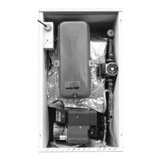
BOILER WILL NOT START Check if mains electricity supply is reaching boiler control panel, making sure control thermostat is turned on and time clock is calling for heat. Mains indicator green should be illuminated. If green light is not illuminated and fuse has been checked, then heating system charge may be low, check black needle on pressure, located inside boiler cabinet (top right hand side) is reading 1 bar or more. -
Page 30: Parts List
PARTS LIST ITEM DESCRIPTION PART No. Control Thermostat COTHCS High Limit Thermostat COTHHL Safety Relief Valve COMPRES Gate Valves COMGATE Grunfoss 25-50 GRUN50 Filling Loop COMLOOP Expansion Vessel Hose COMHOS 12 Litre Expansion Vessel COM12L Door Insulation Kit INSKIT 50 /70 Baffle 70 /90 Baffle Burner See Burner Parts List... -
Page 31: Burner Settings
BURNER SETTINGS BOILER MODEL 50/70 70/90 OUTPUT Btu/h x 100 OUTPUT 20.5 26.4 NOZZLE SIZE AND TYPE US/GPH 0.60 0.65 80 S 80 S OIL PRESSURE FIRING RATE Kg/hr 1.95 2.44 AIR SETTING APPROX. SCALE No. Bacharach SMOKE Scale 12.5 FLUE GAS TEMP . - Page 34 TURKINGTON ENGINEERING LIMITED Unit 12, Whitegate Industrial Estate, Wrexham LL13 8UG Telephone: 01978 363048 or 01978 363049 Fax: 01978 363046 Copyright of the contents of this manual is secured by Turkington Engineering Limited and neither the manual nor any part may be reproduced without permission. Turkington Engineering Limited have a continuing research and development programme which Part occasionally necessitates changes to specifications herein.
Need help?
Do you have a question about the SENATOR and is the answer not in the manual?
Questions and answers