
Summary of Contents for AntennaWorks 8877
- Page 1 2 Meter 144 to 148 MHz 2500 Watt 8877 Amplifier Users Guide 1301 Crooked mile Ct. Placerville, Ca 95815 (916) 765-5811 Revision 1.01, 3/24/00...
-
Page 2: Table Of Contents
Table of Contents ..................2 ABLE OF ONTENTS 1… … … … … … … … … … … … … … … … … S !..3 HAPTER AFETY IRST 2. … … … … … … … … … … … … … … … … .. I ..4 HAPTER NTRODUCTION... -
Page 3: Chapter 1
Chapter 1. Safety First! ~ HIGH VOLTAGE! ~ You can be killed so follow safety tips! ~ Verify there is no voltage present before working with the amplifier. ~ When in doubt do not touch it. ~ Install unit safely in a 19-inch rack. ~ Never open the amp or supply when it is turned on or plugged in. -
Page 4: Chapter 2
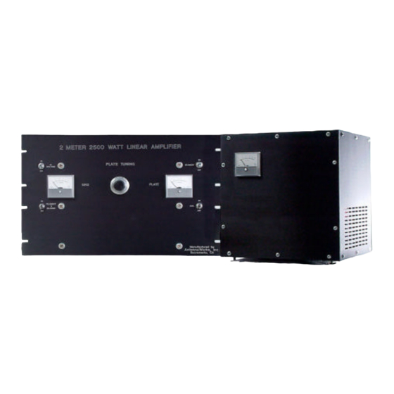
Introduction Welcome to world class VHF operation using the Antenna Works 2 meter 144 to 148 MHz 2500 watt 8877 amplifier. This amplifier has been adapted from the original W6PO 8877 Eimac Amateur Service Newsletter - W6SAI 1971. Many years of design improvements has brought this amplifier to what it is today. -
Page 5: Chapter 3
Chapter 3. Parts List AntennaWorks 2 Meter 144 to 148 MHz 2500 Watt 8877 Amplifier: 2 meter 144 to 148 MHz 2500 watt 8877 amplifier AntennaWorks 2 Meter Amplifier power supply. Conduit for power supply connection High voltage connector OPTIONS:... -
Page 6: Chapter 4
Chapter 4. Assembly Tools and Requirements The following is needed to assemble the Antenna Works amplifier. Phillips #2 Screwdriver Small flat Head Screwdriver Wire Cutter Wire Stripper Solder Solder Iron... -
Page 7: Chapter 5
Chapter 5. Caution If you are uncomfortable or unknowledgeable about high voltage safety and assembly, seek qualified personnel to assemble the amplifier for you. Do not attempt assembly without proper knowledge. -
Page 8: Chapter 6
Chapter 6. Connecting the Power Supply to the Amplifier If you are going to use the gray conduit to go from the supply to the amp you must put all wires including the Yellow high voltage wire through the conduit before you start this section. Fasten the gray conduit from the power supply to the fan and feed all wires including the Yellow high voltage wire out the fan. - Page 9 Look at position 8. 8 is black and is the return. There will only be a low DC voltage here due to the bias configuration, but a good solid connection is most important here. Strip off 3/16” of insulation from the end of the wire. Connect the black wire to position no.
-
Page 10: Chapter 7
Chapter 7. Connecting the High Voltage Yellow Wire If using the gray conduit, you can fasten the gray conduit from the power supply to the fan and feed the Yellow high voltage wire through the fan to its high voltage connector using the high voltage connector supplied. To connect the high voltage yellow wire to the amplifier, strip off 1.25 inches of insulation from the end of the yellow wire from the supply. -
Page 11: Chapter 8
Chapter 8. Connecting the 240 Volt Plug Choose a power plug good for at least 25 amps. Your amp is regulated with a 20-amp push breaker, but a bit of overkill here on your part won’ t hurt, and it will also help your high voltage regulation if you are connected to a high current line. -
Page 12: Chapter 9
Chapter 9. Re-Check all Connections Check all wires; make sure all tools are clear. Verify the screws are tight, the wires are safely connected and that the yellow wire is away from any possible items that could nick, scratch, pinch, cut, pull, or put strain on the cable that could damage the Yellow high voltage wire in any way. -
Page 13: Chapter 10
Chapter 10. Hook up the RF Cables Hook up your radio to a SWR/wattmeter. Hook up the SWR/wattmeter to the tuned input box on the back of the amplifier. Hook up load or antenna to a high power meter, and hook up the meter to the amplifier output. -
Page 14: Chapter 11
Chapter 11. Coax Relay Switching Most people find it nice to use 2 coax runs if an upper pre-amp will be used. If you need 28 volts for relays there is a diode block on the left side of the amp wired for you if needed. -
Page 15: Chapter 12
Chapter 12. Installing the Tube Remove lid from RF deck. Place chimney (Teflon) over tube socket. Take the tube with the anode assembly attached and install it in the tube socket. Put the square inductor clamps over the silver tubing on each side. Slide them flush with the top of the silver tubes. -
Page 16: Rocedure
Chapter 13. Tune and Operation Procedure Keep it legal. Your drive level is up to you. The amplifier is able to exceed output levels regulated by the FCC. We build a product that is able to exceed legal limit so it will work well at legal duty cycles. If you exceed these levels, premature tube wear will occur, so keep it within a drive of 75 watts or less so it will last a long, long time.
Need help?
Do you have a question about the 8877 and is the answer not in the manual?
Questions and answers