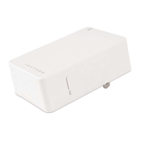
Summary of Contents for INSTEON Smoke Bridge
- Page 1 Smoke Bridge Owner’s Manual 2982-222 Page 1 of 14 2982-222 - Rev: 1/21/2014 8:34 AM...
-
Page 2: Table Of Contents
Make Smoke Bridge a Controller of Multiple Responders ................ 6 Remove Smoke Bridge as a Controller ..................... 6 Remove Smoke Bridge as a Controller of Multiple Responders ............... 7 Local Control Operation and Testing ......................8 Adjust Local Settings ..........................9 INSTEON Blink on Traffic .......................... -
Page 3: About Smoke Bridge
States or the Canadian Electrical Code and local regulations in Canada. Use indoors only. Smoke Bridge is not designed nor approved for use on power lines other than 120V 60Hz, single phase. Attempting to use Smoke Bridge on non- approved power lines may have hazardous consequences. -
Page 4: First Alert Setup
First Alert Smoke Alarm will cycle through its test alert messages Smoke Bridge LED will start blinking red, indicating traffic from the First Alert Smoke Alarm Smoke Bridge LED will stop blinking when First Alert Smoke Alarm finishes sending message... -
Page 5: Make Smoke Bridge A Controller
Make Smoke Bridge a Controller 1) Press and hold Smoke Bridge set button until it beeps Smoke Bridge LED will start blinking green You will have four minutes to complete the next steps before linking mode times out 2) Adjust responder to desired state... -
Page 6: Make Smoke Bridge A Controller Of Multiple Responders
Responder will respond appropriately Remove Smoke Bridge as a Controller If you no longer want Smoke Bridge to control another device (or are removing Smoke Bridge from your network) it is important that you follow the instructions below for each responder. -
Page 7: Remove Smoke Bridge As A Controller Of Multiple Responders
Remove Smoke Bridge as a Controller of Multiple Responders 1) Press and hold Smoke Bridge set button until it beeps LED will start blinking green 2) Press and hold Smoke Bridge set button until it beeps again LED will start blinking red 3) Tap Smoke Bridge set button... -
Page 8: Local Control Operation And Testing
INSTEON devices. To verify Smoke Bridge puts the responders in the correct state, you must put the responders into a different state and then use Set button to test. If you are using software, such as HouseLinc to manage Smoke Bridge, you can create scenes for any of the above groups. -
Page 9: Adjust Local Settings
Default = disabled This setting is only adjustable via software or a central controller. Smoke Bridge LED will blink green if it detects noise that could disrupt communication. It will blink red when it sees traffic to it from its paired First Alert Smoke Alarm. -
Page 10: Specifications
Control groups/commands Low Battery Sensor Malfunction All Clear Blinks red when receiving data from First Alert OneLink Setup LED Blinks green when INSTEON signals are detected Setup LED brightness Adjustable, from off to bright Local control None Commands Supported as responder... - Page 11 32°F to 104°F (0°C to 40°C) Operating humidity range 0-85 % relative Storage temperature range to 158 F (-20 to 70 INSTEON ID label location On backside below unit label Electrical Ratings 120VAC ± 10%, 60Hz Standby Power Consumption 0.8 Watts...
-
Page 12: Troubleshooting
TROUBLESHOOTING Problem Possible Cause Solution The Status LED on Smoke Bridge may not be Make sure Smoke Bridge is not plugged into a Smoke Bridge is not getting power. switched outlet that is turned off. turning on. The Responder might have been reset without Re-Link Smoke Bridge to the Responder. - Page 13 Problem Possible Cause Solution Re-Link the responder to smoke bridge, while the Smoke Bridge can The responder may be responder’s load is on. See the Responder’s turn off a Responder, linked at its off state. Owner’s Manual for more detailed linking rather than on.
-
Page 14: Certification And Warranty
The repair, replacement, or refund that is provided for above shall be the full extent of Seller’s liability with respect to this product. For repair or replacement during the warranty period, call the INSTEON Gold Support line at 800-762-7845 with the Model # and Revision # of the device to receive...

Need help?
Do you have a question about the Smoke Bridge and is the answer not in the manual?
Questions and answers