Table of Contents
Advertisement
Quick Links
Advertisement
Table of Contents

Subscribe to Our Youtube Channel
Summary of Contents for Unitec Peco HF25A
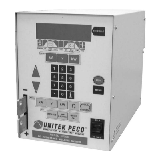
- Page 1 USER'S MANUAL 990-333 Revision B December 2003 HF25A/HF25D 25kHz HIGH FREQUENCY DC RESISTANCE WELDING SYSTEM MODEL NUMBER STOCK NUMBER HF25A10/240 1-280-02-03 HF25A10/400 1-280-02-04 HF25A10/480 1-280-02-05 HF25DA10/240 1-285-02 HF25DA10/400 1-285-02-01 HF25DA10/480 1-285-02-02...
- Page 2 Copyright © 1998, 2003 Unitek Miyachi Corporation The engineering designs, drawings and data contained herein are the proprietary work of UNITEK MIYACHI CORPORATION and may not be reproduced, copied, exhibited or otherwise used without the written authorization of UNITEK MIYACHI CORPORATION. Printed in the United States of America.
-
Page 3: Table Of Contents
CONTENTS Page Chapter 1. Description Section I: Features ..........................1-1 Section II: Major Components ....................... 1-4 Major Components .......................... 1-4 Front Panel Display and Display Controls ..................1-4 Display ............................. 1-5 Display Controls ........................1-6 SCHEDULE Selector Key ....................1-6 Weld Period Selector Keys .................... - Page 4 Contents (Continued) Page Section II: Setup ............................. 2-3 Connections to External Equipment ....................2-3 Weld Head Connections ........................2-4 Foot Pedal-Actuated Weld Head Connection .................. 2-6 Air-Actuated Weld Head Connection ....................2-7 Chapter 3. Using Programming Functions Section I: Menus ............................ 3-1 Overview .............................
- Page 5 Page Section II. Operational States ......................3-15 No Weld State ..........................3-15 Menu State ........................... 3-15 Test State ........................... 3-15 Run State ........................... 3-16 Weld State ........................... 3-17 Monitor State ..........................3-17 Alarm State ........................... 3-18 Section III. Weld Functions ......................... 3-19 Welding Applications ........................
- Page 6 Contents (Continued) Page Single-Pulse Weld Schedule ..................... 4-4 Upslope/Downslope Weld Schedule ..................4-5 Dual-Pulse Weld Schedule ....................... 4-6 Section III. Programming the Weld Monitor .................. 4-7 Section IV. Programming For Active Part Conditioning ............... 4-9 Section V. Adjusting Monitor Limits ................... 4-11 Chapter 5.
- Page 7 CONTACT US Thank you for purchasing a Unitek Peco™ Resistance Welding System Control. Upon receipt of your equipment, please thoroughly inspect it for shipping damage prior to its installation. Should there be any damage, please immediately contact the shipping company to file a claim, and notify Unitek Miyachi at: 1820 South Myrtle Avenue P.O.
- Page 8 SAFETY NOTES DANGER • Do not perform any maintenance Lethal voltages exist within this unit. inside this unit. • Never perform any welding operation without wearing protective safety glasses. This instruction manual describes how to operate, maintain and service the HF25 Resistance Welding System Control, and provides instructions relating to its SAFE use.
- Page 9 HF25D DC RESISTANCE WELDING SYSTEM 990-333...
-
Page 11: Chapter 1. Description Section I: Features
CHAPTER 1 DESCRIPTION Section I: Features Features For the rest of this manual, the Unitek HF25 High Frequency Resistance Welding System control will simply be referred to as the Control. • The Control is a 25 kHz, three-phase, state- of-the-art inverter power supply for joining precision small parts at high speed with controllable rise times. - Page 12 CHAPTER 1: DESCRIPTION • You can program the Control from the front <MAIN MENU> panel, using simplified key clusters and on- 1. SETUP COMMUNICATION screen data fields. A screen MAIN MENU 2. WELD COUNTER 6. RELAY allows you select all of the system setup 3.
- Page 13 CHAPTER 1: DESCRIPTION • The Control has a Linear Variable Differential Transformer (LVDT) option that allows the user to: − Measure Initial Part Thickness − Measure Final Part Thickness − Measure displacement during welding − Stop the weld energy after a programmable displacement is reached. Programmable relay outputs are also provided with this option.
-
Page 14: Section Ii: Major Components
CHAPTER 1: DESCRIPTION Section II: Major Components Major Components The major components are the front panel, which contains the operator’s controls and indicators, and the rear panel, which contains fuses, circuit breakers and power and signal connectors. The rear panel connections are discussed in Chapter 2. -
Page 15: Display
CHAPTER 1: DESCRIPTION Display Liquid Crystal Display (LCD) The Liquid Crystal Display (LCD) on the front panel allows you to locally program the Control with the front panel controls, and read the results of a weld process following its initiation. The LCD has three distinct functions, depending on the active mode of the Control. -
Page 16: Display Controls
CHAPTER 1: DESCRIPTION Display Controls There are three display control functions: • Selector Key SCHEDULE • Weld Period Selector Keys • Time/Energy Selector Keys SCHEDULE Key Puts the Control into the weld schedule selection mode. Use the keypad to directly enter a desired weld schedule (refer to Front Panel Data Entry and Mode Controls in this section), then press the key. -
Page 17: Key Pad
CHAPTER 1: DESCRIPTION Front Panel Data Entry and Mode Keys Key Pad The keypad consists of the numeric keys and the up/down keys. Numeric Keys: The numeric keys allow you to: • Enter or modify weld period time and energy values •... -
Page 18: Monitor Keys
CHAPTER 1: DESCRIPTION NOTE: Selecting the voltage feedback mode requires you to make a test weld when the voltage or weld pulse time is changed. The test weld optimizes the Control feedback performance. The weld status message TEST disappears after the internal control parameters are optimized. -
Page 19: Lvdt Keys
CHAPTER 1: DESCRIPTION LVDT Keys Pressing displays the displacement monitor. This screen shows the DISTANCE results of the most recent weld. This screen also allows the operator to set limits that automatically interrupt the weld when they are reached. You can also program the power monitor to output an alarm when the limits are exceeded Pressing allows the operator to reset the zero point for distance... -
Page 21: Space Requirements
CHAPTER 2 INSTALLATION AND SETUP Section I: Installation Unpacking The Control is shipped to you completely assembled, together with the accessories you ordered and a shipping kit. The contents of the shipping kit, available accessories, and contents of the Datacom Kit are listed in Appendix A, Technical Specifications. -
Page 22: Utilities
CHAPTER 2: INSTALLATION AND SETUP Utilities Power Because of the different electrical requirements for the countries in which the Control is used, the Control is shipped without a power cable connector. The required connections for your power cable connector are described in Appendix B, Electrical and Data Connections. Input power requirements for the Control are as listed below. -
Page 23: Section Ii: Setup
CHAPTER 2: INSTALLATION AND SETUP Section II: Setup Connections to External Equipment All connections, other than the weld cable connections, between the Control and external equipment are made through the rear panel. Rear Panel Components The weld cable connections from the weld head are made at the weld cable terminals on the front panel. HF25D DC RESISTANCE WELDING SYSTEM 990-333... -
Page 24: Weld Head Connections
CHAPTER 2: INSTALLATION AND SETUP Weld Head Connections 1. Connect one end of a weld cable to the negative (-) welding transformer terminal on the Control. Connect one end of the second weld cable to the positive (+) welding transformer terminal on the Control. - Page 25 CHAPTER 2: INSTALLATION AND SETUP Connect the voltage sensing cable clips that are packed in the shipping kit to the voltage sensing cable leads. Use either the ¼” or 1/8” diameter clip, as appropriate to the electrode diameter. Attach a clip directly to each electrode as shown on the right.
-
Page 26: Foot Pedal-Actuated Weld Head Connection
CHAPTER 2: INSTALLATION AND SETUP Foot Pedal-Actuated Weld Head Connection 1. Adjust the weld head force adjustment knob to produce 5 units of force, as displayed on the force indicator index. Connect the weld head firing switch cable connector to the Control firing switch cable connector. -
Page 27: Air-Actuated Weld Head Connection
CHAPTER 2: INSTALLATION AND SETUP Set the circuit breaker on the rear panel of the Control to the ON position. The default screen will be displayed. You will use this screen to enter welding parameters. See Chapter 3, Using Weld Functions and Chapter 4, Operating Instructions. - Page 28 CHAPTER 2: INSTALLATION AND SETUP Refer to the weld head manufacturer user’s manual. Connect the weld head air valve solenoid cable connector to the Control connector. AIR VALVE DRIVER NOTE: This connector supplies 24 VAC power only, and will not drive 115 VAC air valves. 6.
-
Page 29: Chapter 3. Using Programming Functions
CHAPTER 3 USING PROGRAMMING FUNCTIONS Section I: Menus Overview You program the Control through the MAIN MAIN MENU screen and its sub-menus. You go to the MENU 1. SETUP 5. COMMUNICATION 2. WELD COUNTER 6. RELAY screen by pressing the key on MAIN MENU MENU... -
Page 30: Weld Counter
CHAPTER 3: USING PROGRAMMING FUNCTIONS 2. WELD COUNTER From the , press the MAIN MENU <WELD COUNTERS> to go to the screen. WELD COUNTERS 1. TOTAL WELDS 0000000 2. OUT OF LIMITS HIGH 000000 The total welds counter increments each 3. -
Page 31: System Security
CHAPTER 3: USING PROGRAMMING FUNCTIONS 4. SYSTEM SECURITY From the , press the key to go to up MAIN MENU <SYSTEM SECURITY> screen. With this screen, SYSTEM SECURITY 1. SCHEDULE LOCK 2. SYSTEM LOCK you can protect the weld schedules from 3. -
Page 32: Communication
CHAPTER 3: USING PROGRAMMING FUNCTIONS 5. COMMUNICATION The following menu screens tell you how to set the Control's communication and data options. However, to enable the Control to perform these functions, you must install the software from the optional DC25/UB25/HF25 Datacom Communications Interface Kit, commonly referred to as "the Datacom kit”... -
Page 33: Number
CHAPTER 3: USING PROGRAMMING FUNCTIONS • In the role, the Control will send weld data only when requested by the host SLAVE computer. For RS-485 installations with mulitple controls on one communications channel, this role is preferred. NOTE: For weld data collection and host computer control information, refer to the Datacom Operator Manual, which describes how to use the options. -
Page 34: Relay
CHAPTER 3: USING PROGRAMMING FUNCTIONS 6. RELAY 1. From the , press the MAIN MENU <RELAY> to go to the output state RELAY 1. RELAY 1 ON WHEN ALARM 2. RELAY 2 ON WHEN ALARM selection menu, shown at the right. The Control has two relays that can provide dry-contact signal outputs under four conditions. -
Page 35: Reset To Defaults
CHAPTER 3: USING PROGRAMMING FUNCTIONS 8. RESET TO DEFAULTS From the , press the key to go to MAIN MENU <RESET TO DEFAULTS> menu, as shown at the RESET TO DEFAULTS 1. RESET SYSTEM PARAMETERS 2. RESET ALL SCHEDULES right. Through this menu, you may reset all EPROM DATE: XX-XX-XX XX:XX VX.XX system programmed parameters and all weld schedules to the original factory default settings... -
Page 36: Chain Schedules
CHAPTER 3: USING PROGRAMMING FUNCTIONS 9. CHAIN SCHEDULES This feature allows you to automatically change from any weld schedule to any other schedule after a preset count, creating a "chain" of schedules that can accommodate a variety of welding needs. For example: •... - Page 37 CHAPTER 3: USING PROGRAMMING FUNCTIONS Use the (Up/Down) keys on the CHAIN SCHEDULE SETUP front panel to scroll vertically through SCHEDULE NUMBER WELD COUNT NEXT Ø4 ØØØ1 Ø4 the schedules to highlight the weld Ø5 ØØØ1 Ø5 count for the schedule you want to Ø6 ØØØ1 Ø6...
-
Page 38: Setup 1
CHAPTER 3: USING PROGRAMMING FUNCTIONS SETUP 1 1. Footswitch Weld Abort From the screen, press the key to toggle between . This function controls how SETUP 1 the Control interfaces with a foot switch, a force firing switch, or a programmable logic control (PLC). Any of these switches could be the weld initiation switch in your system setup. -
Page 39: Firing Switch
CHAPTER 3: USING PROGRAMMING FUNCTIONS 3. Firing Switch With the screen displayed, press the key to select this function. The firing switch input, in SETUP 1 conjunction with or without inputs from the foot switch input, initiates the weld energy sequence. Select the required switch type by pressing the , or key. -
Page 40: Mechanical
CHAPTER 3: USING PROGRAMMING FUNCTIONS 1. MECHANICAL With the screen INPUT SWITCH SELECT <INPUT SWITCH SELECT> displayed, press to display the 1. MECHANICAL SWITCH NORMAL OPEN 2. MECHANICAL SWITCH NORMAL CLOSED switch select menu. MECHANICAL Select the required switch type by pressing , or key. -
Page 41: Control Signals Select
CHAPTER 3: USING PROGRAMMING FUNCTIONS 5. CONTROL SIGNALS SELECT From the screen, press the key to access the menu screen. This SETUP 1 CONTROL SIGNALS SELECT function selects the type of external input switch to be used by the control signals input and how these switches are activated. -
Page 42: Update Graph After Weld
CHAPTER 3: USING PROGRAMMING FUNCTIONS 4. Update Graph After Weld From the screen, press the key to toggle the update graph after weld function. SETUP 1 line will now reflect your state selection. UPDATE GRAPH AFTER WELD means that the actual weld energy profile will overlay the programmed weld profile after each weld is made. -
Page 43: Section Ii. Operational States
CHAPTER 3: USING PROGRAMMING FUNCTIONS Section II. Operational States The Control has seven operational states: NO WELD WELD MENU MONITOR TEST ALARM You go to the states through the control panel. The NO WELD MENU TEST MONITOR WELD states are functions of the force firing switch and foot switch input states. ALARM No Weld State Setting the... -
Page 44: Run State
CHAPTER 3: USING PROGRAMMING FUNCTIONS Run State Pressing the key puts the Control in the run state. In the run state, the screen shows a trace that represents your programmed parameters for a given weld schedule. You may select a different weld schedule to be programmed with key and keypad, or with the up SCHEDULE... -
Page 45: Weld State
CHAPTER 3: USING PROGRAMMING FUNCTIONS Weld State Once weld current is flowing, the Control is in the state. You can terminate weld current in five WELD ways: • Remove the first level of a single-level foot switch, assuming weld abort is ON. •... -
Page 46: Alarm State
CHAPTER 3: USING PROGRAMMING FUNCTIONS Alarm State The Control automatically recognizes many alarm conditions. The example WELD SWITCH alarm screen shown at IN NO WELD POSITION the right is displayed when you attempt to initiate a weld with the switch WELD/ NO WELD in the position. -
Page 47: Section Iii. Weld Functions
CHAPTER 3: USING PROGRAMMING FUNCTIONS Section III. Weld Functions Welding Applications Most welding applications require the use of Squeeze Weld 1 Down 1 Cool Weld 2 Down 2 Hold State 0-999ms 0-9.9ms 0-9.9ms 0-9.9ms 0-9.9ms 0-9.9ms 0-9.9ms 0-9.9ms 0-999ms State specialized weld functions. -
Page 48: Weld Head Applicability
CHAPTER 3: USING PROGRAMMING FUNCTIONS Weld Head Applicability The weld functions can be used with Unitek Peco force fired, manual weld heads; air actuated weld heads; or Series 300 Electronic Force Controlled Weld Heads. For manually actuated weld heads and the Series 300 Weld Heads, weld current begins when the force-firing switch closes. -
Page 49: Section Iv: Using Weld And Monitor Functions
CHAPTER 3: USING PROGRAMMING FUNCTIONS Section IV: Using Weld and Monitor Functions Overview To ensure accurate, consistent welds, the Control delivers extremely precise pulses of energy to the weld head. Each pulse is comprised of weld-time and weld-energy (voltage, current, or power) values pre- programmed by the user. -
Page 50: Weld Schedule Definition
CHAPTER 3: USING PROGRAMMING FUNCTIONS Weld Schedule Definition Weld Schedule is the name given to each of 31 separate weld profiles stored in the Control, numbered from 01 31. A weld profile is the graphic representation [or waveform] of the numeric weld-time and weld-energy values. -
Page 51: Welding Applications
CHAPTER 3: USING PROGRAMMING FUNCTIONS Welding Applications Weld Pulse Profile Typical Application Can be used for many of spot-welding applications. Use on flat parts Single-Pulse without plating, or on conductive parts such as those made of copper or brass. Upslope/Downslope should be used for the majority of spot welding Upslope/Downslope applications. -
Page 52: Upslope/Downslope Weld Profile
CHAPTER 3: USING PROGRAMMING FUNCTIONS Upslope/Downslope Weld Profile Applications • Round or non-flat parts and most resistive materials. Description Upslope allows a gradual application of weld energy which permits the parts to come into better contact with each other reducing the electrode to part contact resistances. Upslope can allow a smaller electrode force to be used, resulting in a cleaner appearance by reducing electrode indentation, material pickup and electrode deformation. - Page 53 CHAPTER 3: USING PROGRAMMING FUNCTIONS Upslope will also help to displace plating and/or oxides, reduce flashing and spitting, or reduce thermal shock when welding parts containing glass-to-metal seals. In the normal application of dual-pulse, the Pulse 1 weld period provides sufficient heat to displace the plating or oxides, seat the electrodes against the base metals, and force the parts into intimate contact.
-
Page 54: Section V. Programmable Feedback Modes
CHAPTER 3: USING PROGRAMMING FUNCTIONS Section V. Programmable Feedback Modes Introduction The feedback mode (current, voltage, power) is one of the selections entered when programming a weld schedule. Programming weld schedules is explained in chapter 4, Operating Instructions. Current Mode Application •... -
Page 55: Section Vi. Weld Monitor
CHAPTER 3: USING PROGRAMMING FUNCTIONS Section VI. Weld Monitor Introduction The Control's feedback sensors not only control weld energy output, but they can also be used to monitor each weld. The Control's monitor features allow you to view graphic representations of welds, visually compare programmed welds to actual welds, look at peak or average energy values, set upper and lower limits for welds, and make use of these features: •... -
Page 56: How It Works
CHAPTER 3: USING PROGRAMMING FUNCTIONS How It Works Both constant current feedback and constant voltage feedback modes are limited in their ability to deal with varying levels of part contamination and oxide. If constant current feedback were used, the power supply would ramp the voltage to very high levels in order to achieve current flow through the oxide. -
Page 57: Energy Limits
CHAPTER 3: USING PROGRAMMING FUNCTIONS Energy Limits Applications • Part-to-part positioning problems • Electrode-to-part positioning problems • Parts with narrow weld window Energy Limits can be used in two different ways: • To detect work piece resistance changes that occur when parts are positioned incorrectly at the weld head. -
Page 58: Pre-Weld Check
CHAPTER 3: USING PROGRAMMING FUNCTIONS In this case, the operator has selected the option to terminate the weld energy under this condition, so the energy limits monitor terminates the Pulse 1 weld and inhibits the Pulse 2 weld if it had been programmed. -
Page 59: Chapter 4. Operating Instructions Section I: Before You Start
CHAPTER 4 OPERATING INSTRUCTIONS Section I: Before You Start This Chapter tells you how to turn the Control ON, use menu screens to customize operating parameters, match the Control to your welding system, and how to operate the Control. This chapter is divided into the following sections: •... -
Page 60: Initial Setup: Pre-Operational Checks
CHAPTER 4. OPERATING INSTRUCTIONS Initial Setup: Pre-Operational Checks Always perform these checks before attempting to operate the Control. Connections Verify that the Control has been connected to a manual or air-actuated weld head as described in Chapter 2 of this manual. Verify that the Emergency Stop Switch shorting wires are connected or verify that an Emergency Stop Switch is connected properly. -
Page 61: Section Ii. Programming Weld Schedules
CHAPTER 4. OPERATING INSTRUCTIONS Section II. Programming Weld Schedules Introduction The Control comes with 99 factory-installed weld schedules, numbered from 01 through 99. Each schedule looks like the display on the right. See Section III, Using HF25 Welding And Monitoring Functions for descriptions of the features available in weld schedules. -
Page 62: Single-Pulse Weld Schedule
CHAPTER 4. OPERATING INSTRUCTIONS Single-Pulse Weld Schedule NOTE: If you are using the optional LVDT, you must perform the procedures described in Appendix D, LVDT Option, Section 4, Operating Instructions in addition to the procedures below. Press the key, then select a Weld Schedule using either the arrows or SCHEDULE the numeric keypad. -
Page 63: Upslope/Downslope Weld Schedule
CHAPTER 4. OPERATING INSTRUCTIONS Upslope/Downslope Weld Schedule NOTE: If you are using the optional LVDT, you must perform the procedures described in Appendix D, LVDT Option, Section 4, Operating Instructions in addition to the procedures below. Press the key, then select a Weld Schedule using either the arrows or SCHEDULE the numeric keypad. -
Page 64: Dual-Pulse Weld Schedule
CHAPTER 4. OPERATING INSTRUCTIONS Dual-Pulse Weld Schedule NOTE: If you are using the optional LVDT, you must perform the procedures described in Appendix D, LVDT Option, Section 4, Operating Instructions in addition to the procedures below. Press the key, then select a Weld Schedule using either the arrows or SCHEDULE the numeric keypad. -
Page 65: Section Iii. Programming The Weld Monitor
CHAPTER 4. OPERATING INSTRUCTIONS Section III. Programming the Weld Monitor Press the key, then select a Weld Schedule using either the arrows SCHEDULE or the numeric keypad. Fire the welder and view the output waveform (shaded graph) on the display. From the keys section on the front panel, press the MONITOR... - Page 66 CHAPTER 4. OPERATING INSTRUCTIONS • stops Pulse 1 immediately after upper or lower APC: STOP PULSE 1/ALLOW PULSE 2 energy limits are exceeded, but allows Pulse 2 to fire. This function will not operate if both pulses are joined without a cool time. NOTE: See Section IV, Programming For Active Part Conditioning.
-
Page 67: Section Iv. Programming For Active Part Conditioning
CHAPTER 4. OPERATING INSTRUCTIONS Section IV. Programming For Active Part Conditioning Before you program for Active Part Conditioning, make sure you are familiar with these procedures described in this manual: • Chapter III, Using HF25 Welding And Monitoring Functions • Chapter IV, Section III, Programming The Weld Monitor Press the key, then select a Weld Schedule using either the... - Page 68 CHAPTER 4. OPERATING INSTRUCTIONS Since different levels of oxide require different amounts of time to reach the current limit, return to the screen and extend the programmed weld time (usually double the time works). This will ensure that there will be enough time for the current to rise and reach the limit, even with heavily oxidized parts.
-
Page 69: Section V. Adjusting Monitor Limits
CHAPTER 4. OPERATING INSTRUCTIONS Section V. Adjusting Monitor Limit Values The Control allows you to adjust extremely precise limits for the amount of energy and weld time. Like all welding processs development, you’ll need to make several test welds, and view the waveforms and limits of actual welds in order to “fine tune”... - Page 70 CHAPTER 4. OPERATING INSTRUCTIONS Set an using the procedures in Section III, Programming the UPPER LIMIT LOWER LIMIT Weld Monitor. 2. Perform a weld to see how the limits (dotted lines) appear compared to the weld graph. 3. Raise or lower the as necessary using the procedures in Section UPPER LIMIT LOWER LIMIT...
-
Page 71: Section I: Introduction
CHAPTER 5 MAINTENANCE Section I. Introduction General Kinds of Problems It has been our experience that most resistance welding power supply ‘problems’ are caused by lack of material control, process control and electrode tip surface maintenance. The problems that you might encounter fall into two groups: •... -
Page 72: Section Ii: Troubleshooting
CHAPTER 5. MAINTENANCE Section II. Troubleshooting Troubleshooting Problem Cause (in order of probability) Problem Cause (in order of probability) Electrode 1. Excessive current/energy set at HF25 Electrode 1. Excessive current/energy set at HF25 Damage Sparking 1. Excessive or insufficient weld head 1. -
Page 73: Alarm Messages
CHAPTER 5. MAINTENANCE Problem Cause (in order of probability) Problem Cause (in order of probability) Weld Piece 1. Excessive weld time set at HF25 Weld Piece 1. Excessive weld time set at HF25 Over- Discoloration 2. Excessive current/energy set at HF25 1. - Page 74 CHAPTER 5. MAINTENANCE Alarm Message Description Corrective Action CURRENT 1 Actual weld current is greater than the Reset the Upper Limit for Weld1 to a larger GREATER THAN user set Upper Limit value for Weld1. value. UPPER LIMIT CURRENT 2 Actual weld current is greater than the Reset the Upper Limit for Weld2 to a larger GREATER THAN...
- Page 75 CHAPTER 5. MAINTENANCE Alarm Message Description Corrective Action FIRING DIDN’T The Firing Switch on a Unitek air Press RUN and readjust the air pressure to the CLOSE IN 10 actuated weld head did not activate Unitek air actuated weld head. SECONDS within 10 seconds after the Foot Switch was initially activated.
- Page 76 CHAPTER 5. MAINTENANCE Alarm Message Description Corrective Action NO WELD Cable connecting the Control and Power Verify installation of the welding TRANSFORMER PCB’s is open. transformer/rectifier module connections. DETECTED Cable connecting the Power PCB to the Weld Transformer is open. POWER 1 Actual weld power is greater than the Weld splash can cause the actual weld power to...
- Page 77 CHAPTER 5. MAINTENANCE Alarm Message Description Corrective Action SYSTEM User programmed the HF25/26 to CAUTION: Be careful when using the MENU PARAMETERS ARE automatically reset all I/O and other default features. There is no way to restore a RESET system parameters to their factory set default action.
- Page 78 CHAPTER 5. MAINTENANCE Alarm Message Description Corrective Action WELD STOP - The user set Upper Limit value has been This is a MONITOR LIMITS feature activated LIMIT REACHED exceeded and automatically terminated by the selecting the ENERGY key, then the weld energy. programming the Upper Limit values for Weld1 and Weld2.
-
Page 79: Section Iii: Maintenance
CHAPTER 5. MAINTENANCE Section III. Maintenance Electrode Maintenance When a welding schedule has been suitable for a particular welding application over many welds, but poor quality welds are now resulting, electrode deterioration could be the problem. If you need to increase welding current to maintain the same weld heat, the electrode tip has probably increased in surface area (mushroomed), effectively increasing weld current density, thus cooling the weld. - Page 80 CHAPTER 5. MAINTENANCE Section III. Repair Service If you have problems with your Control that you cannot resolve, please contact our service department at the address, phone number, or e-mail address indicated in the Foreword of this manual. HF25D DC RESISTANCE WELDING SYSTEM 5-10 990-333...
-
Page 81: Chapter 6. Calibration
CHAPTER 6 CALIBRATION Calibration The calibration procedure is initiated at the main menu, as described in Chapter 3, Using Programming Functions, Section I, Menus. . The Control is calibrated by the software, using inputs from a calibration setup during a weld process. Following a few calibration inputs, the Control will adjust itself and store the calibration values in RAM, where they will be used as standards for the operational welding parameters. -
Page 82: Calibration Procedure
CHAPTER 6: CALIBRATION Calibration Procedure Initial Calibration Setup 1. Connect the calibration setup to the Control as shown. 2. Turn the Control ON. <MAIN MENU> Press the key to bring up the MENU 1. SETUP main menu screen. COMMUNICATION 2. WELD COUNTER 6. - Page 83 CHAPTER 6: CALIBRATION The first calibration screen is the . This screen asks for the actual CALIBRATION SHUNT value of the 1000 micro-ohm shunt. The actual value is printed on the exterior of the R7500-8 shunt. Enter this value using the number keys, and press to continue.
- Page 84 CHAPTER 6: CALIBRATION Final Calibration Setup HF25D DC RESISTANCE WELDING SYSTEM 990-333...
-
Page 85: Calibrating The Lvdt
CHAPTER 6: CALIBRATION 10. The last calibration screen is Press the key. The 5. END OF CALIBRATION. MENU calibration is now complete. Calibrating the LVDT If you are using the LVDT option, follow the calibration procedures described in Appendix D, LVDT Option, Section 3, LVDT Calibration. -
Page 86: Appendix A. Technical Specifications
APPENDIX A TECHNICAL SPECIFICATIONS NOTE: The specifications listed in this appendix may be changed without notice. Power Input Power Line ....................50-60 Hz, 3 phase Input Voltage Range at Maximum Output Current HF25A10/240 ....................192-264 VAC at 25A HF25DA10/240 ....................192-264 VAC at 25A HF25A10/400 .................... - Page 87 APPENDIX A: TECHNICAL SPECIFICATIONS Performance Capabilities Number of Weld Schedules ........................100 Programmable Weld Periods: Squeeze ..........................0 - 999 ms Upslope 1 ..........................0 - 99 ms Weld 1 ...........................0 - 99 ms Downslope 1 ..........................0 - 99 ms Cool ...........................0 - 99 ms Upslope 2 ..........................0 - 99 ms Weld 2 ...........................0 - 99 ms Downslope 2 ..........................0 - 99 ms...
- Page 88 APPENDIX A: TECHNICAL SPECIFICATIONS Input Signals NOTE: Except where parenthetically noted below, all input signals accept 5 to 24 VDC, normally open or normally closed, positive or negative logic. Inputs are optically isolated. Firing Switch Initiation: 1-level foot switch, 2-level foot switch or opto firing switch. Remote Control Barrier Strip: Remote weld schedule select, process inhibit, emergency stop and force control (0 - 5 VDC).
-
Page 89: Optional Accessories
APPENDIX A: TECHNICAL SPECIFICATIONS Shipping Kit Contents Part Description Part No. Voltage Sense Cable Assembly 4-32998-01 Power Supplies Operator’s Guide 991-342 Machine Bolt, Hex Head, 5/16-18 x 1 160-016 Jam Nut, 5/16-18, for weld cable 465-049 Flat Washer, 5/16, for weld cable 755-044 Spring Lock Washer 755-228... -
Page 90: Appendix B. Electrical And Data Connections
APPENDIX B ELECTRICAL AND DATA CONNECTIONS Electrical Connection As described in Chapter 2, you need to supply a connector for the Control input power cable (refer to diagram below for wiring information). Connect the Control power cable to a 3-phase, 50/60Hz power source. The voltage range for each model is set at the factory by a set of two jumper plugs. - Page 91 APPENDIX B: ELECTRICAL AND DATA CONNECTIONS I/O Signal Interface General Description I/O Signal Interface Physical Organization All signals transferred between the Control and external devices enter and leave the unit through the I/O signal interface. The interface consists of terminal block plugs connected to bulkhead connectors, connectors, and additional connectors (as shown) attached to a CONTROL SIGNALS MONITOR...
- Page 92 APPENDIX B: ELECTRICAL AND DATA CONNECTIONS The bulkhead connectors that receive the six removable terminal block plugs are connectors J1, J2 and J3 on the control board. The terminal block plug to control board connector pin relationship is as follows: Pins 1-10 Pins 11-20 Pins 1-10...
- Page 93 APPENDIX B: ELECTRICAL AND DATA CONNECTIONS Connections Connect an approved, normally closed emergency stop switch across the 2-foot (61 cm) operator emergency stop switch cable. The cable is routed through the side of the connector box on the rear panel. When the switch is operated (opened), it de-energizes the main power contactor, removing three- phase input power to the Control.
- Page 94 APPENDIX B: ELECTRICAL AND DATA CONNECTIONS Force Firing Switch Input Schematic Diagram – Standard Configuration Force Firing Switch Input Schematic Diagram -- Alternate Configuration (for PLC) HF25D DC RESISTANCE WELDING SYSTEM 990-333...
- Page 95 APPENDIX B: ELECTRICAL AND DATA CONNECTIONS FIRING SWITCH Connector Pin Assignment Summary Signal Destinations Pin No. Comments Control Voltage Current Name Type Board FIREG Digital 2-12 J1-12 SGND 20mA Firing switch ground FIRE1 Digital 2-11 J1-11 +24V 10mA Firing switch normally open contact Shld CGND...
- Page 96 APPENDIX B: ELECTRICAL AND DATA CONNECTIONS Two-Level Foot Switch Input Schematic Diagram –Standard Configuration Two-Level Foot Switch Input Schematic Diagram -- Alternate Configuration (for PLC) HF25D DC RESISTANCE WELDING SYSTEM 990-333...
- Page 97 APPENDIX B: ELECTRICAL AND DATA CONNECTIONS FOOT SWITCH Connector Pin Assignment Summary Signal Destinations Voltage Comments Cntrol Current Name Type Board CGND 2-15 J1-15 CGND Chassis ground FOOT1 Digital 2-16 J1-16 +24V 10mA Foot switch SW1 (Level 1) normally open contact FOOT2 Digital 2-17...
- Page 98 APPENDIX B: ELECTRICAL AND DATA CONNECTIONS PLC Timing Diagram BCD Welding Schedule Selection Scheme Weld Bit 2 Bit 2 Bit 2 Bit 2 Bit 2 Bit 2 Bit 2 Schedule Pin 1 Pin 2 Pin 3 Pin 4 Pin 12 Pin 5 Pin 14 5-98...
- Page 99 APPENDIX B: ELECTRICAL AND DATA CONNECTIONS Schedule Initiation Function In addition to selecting weld schedules, the remote schedule selection inputs can be used to automatically initiate the welding cycle, eliminating the need for a firing switch or foot switch input. By selecting the option from the main menu, weld energy will flow 20 FIRING SWITCH: REMOTE...
- Page 100 APPENDIX B: ELECTRICAL AND DATA CONNECTIONS Mechanical Switch or Opto Coupler Input Schematic Diagram HF25D DC RESISTANCE WELDING SYSTEM 990-333 B-11...
- Page 101 APPENDIX B: ELECTRICAL AND DATA CONNECTIONS PLC Voltage Input Schematic Diagram HF25D DC RESISTANCE WELDING SYSTEM B-12 990-333...
- Page 102 APPENDIX B: ELECTRICAL AND DATA CONNECTIONS Standard Air Valve Driver Output Function The Control supplies a switched 24 VAC output to drive the air valve solenoid of a standard Unitek 24 VAC air actuated weld head. Connections Connect the weld head air valve solenoid cable to the four-pin connector on the AIR VALVE DRIVER connector box.
- Page 103 APPENDIX B: ELECTRICAL AND DATA CONNECTIONS EZ Air Valve Driver Input/Output Function The Control supplies a switched +24 VDC output to the EZ-Air air valve driver solenoids. This valve driver system incorporates multiple solenoids that prevent weld over-force caused by excessive air pressure.
- Page 104 APPENDIX B: ELECTRICAL AND DATA CONNECTIONS EZ Air Valve Driver I/O Schematic Diagram – Alternate Configuration (for PLC) HF25D DC RESISTANCE WELDING SYSTEM 990-333 B-15...
- Page 105 APPENDIX B: ELECTRICAL AND DATA CONNECTIONS Connections Connect the EZ-Air air valve driver solenoid cable connector to the seven-pin AIR VALVE DRIVER connector on the Control connector Box. EZ AIR VALVE DRIVER Connector Pin Assignments Signal Destinations Max Voltage Comments Current Name Type...
- Page 106 APPENDIX B: ELECTRICAL AND DATA CONNECTIONS Relay Outputs Function Four mechanical relays on the control board can be independently programmed to supply alarm or weld status contact signal outputs. You can access the programming function through the main menu, as described in Chapter 3.
- Page 107 APPENDIX B: ELECTRICAL AND DATA CONNECTIONS Relay Outputs Schematic Diagram Relay Contact Output Connector Pin Assignments Signal Destinations Control CONT BD Pin Max Voltage Comments Name Type Current Conn Pin J2-13 RELAY1+ AC/DC 4-33 24VDC/AC Relay output 1pos J2-14 RELAY1- AC/DC 4-34 24VDC/AC...
- Page 108 APPENDIX B: ELECTRICAL AND DATA CONNECTIONS Monitor Output Monitor I/O Schematic Diagram HF25D DC RESISTANCE WELDING SYSTEM 990-333 B-19...
- Page 109 APPENDIX B: ELECTRICAL AND DATA CONNECTIONS MONITOR Connector Pin Assignment Summary Cntrl Bd Signal Active Voltage Current Comments Conn J6 State Name Type Not used SECCUR Analog 0-5VDC Secondary current PRICUR Analog 0-5VDC Primary current ADPOS Analog 0-5VDC Position DOUT Digital Not used Not used...
-
Page 110: Appendix C. System Timing
APPENDIX C HF25 DC RESISTANCE WELDING SYSTEM TIMING Basic Weld Operation: Air Head System with Two-Level Foot Switch Definitions Delay time from Foot Switch Level 1 closure to Weld Force start. Maximum delay time is 1 ms plus switch debounce time. Switch debounce time can be set to none, 10, 20, or 30 ms with the menu screen. - Page 111 APPENDIX C: SYSTEM TIMING Basic Weld Operation: Manual Head System with Firing Switch Operation Definitions DELAY Delay time from firing switch closure to the start of the weld sequence (that is, start of ). Maximum time is 2 ms, plus switch debounce time. DELAY Squeeze time.
- Page 112 APPENDIX C: SYSTEM TIMING Basic Weld Operation: System with Remote Firing Switch NOTE: The firing switch mode is selected under the Setup 1 menu. Definitions Delay time from Remote Schedule Select Signal ON to the start of the weld sequence DELAY (that is, start of time is 23 ms.
-
Page 114: Appendix Dlvdt Option
APPENDIX D LVDT OPTION Section I. Description Overview The optional Linear Variable Differential Transformer (LVDT) is a combination of an electro- mechanical device attached to the weld head, which is electronically linked to software installed in the Control. This combination will be referred to simply as the LVDT. This option allows the user to: •... - Page 115 APPENDIX D: LVDT OPTION LVDT Specifications Stroke 1.0” (25.4mm) maximum Absolute Accuracy See Following Graph Weld Displacement Accuracy 0.003” (0.076mm) Displayed Resolution 0.001” (0.01mm) Measurement Resolution 0.00025” (0.006mm) Repeatability Maximum Weld Rate 2 weld per second NOTE: The suggested minimum weld force to use with the LVDT is 2 lbs. (0.9 kgf). HF25 DC RESISTANCE WELDING SYSTEM 990-333...
- Page 116 APPENDIX D: LVDT OPTION Section II. LVDT Adjustment LVDT Installed on Typical Weld Head The LVDT is most accurate in the middle of its one-inch stroke. Therefore, best measurement performance is achieved by adjusting the LVDT so that welding occurs in the middle of its stroke. The following instructions apply to the LVDT in the 80 DSPK: If Total Electrode Stroke Is LESS Than 0.5-inch: Loosen the adjusting screws and move the LVDT up or down so that when the electrodes are closed, the...
- Page 117 APPENDIX D: LVDT OPTION Section III. Before You Start • Check the connections from the LVDT on the weld head to the Control. • Verify that the LVDT moves freely with the electrodes. • Calibrate the LVDT following the procedures in Section IV, LVDT Calibration. •...
- Page 118 APPENDIX D: LVDT OPTION Section IV. LVDT Calibration Overview Before using the LVDT during welding, it is extremely important to calibrate the LVDT in order to verify that the measurements displayed on the LCD screen match the actual distance between the electrodes.
- Page 119 APPENDIX D: LVDT OPTION Press to input the calibration gauges. PRE-CALIBRATION 1. TEST HF25 (T-232 REQUIRED) 2. CALIBRATE HF25 3. RESET CALIBRATION 4. SET CURRENT SHUNT VALUE 6. LVDT GAUGE 5. TEST SERIAL PORT 7. CALIB LVDT Example: Using a gauge that is 0.100”, LVDT CALIBRATION enter the numbers , and...
- Page 120 APPENDIX D: LVDT OPTION A message will then flash to release the LVDT QUICK CAL footswitch. Do so and the screen on PUT THE THICK CALIBRATION GAUGE OF 0.100 in the right appears. Verify the electrodes BETWEEN THE ELECTRODES. are securely installed in the electrode PRESS FOOTSWITCH holders.
- Page 121 APPENDIX D: LVDT OPTION Press 7 to start calibration. PRE-CALIBRATION 1. TEST HF25 (T-232 REQUIRED) 2. CALIBRATE HF25 3. RESET CALIBRATION 4. SET CURRENT SHUNT VALUE 6. LVDT GAUGE 5. TEST SERIAL PORT 7. CALIB LVDT NUMBER Select, MENU Previous menu Verify that the electrodes are securely LVDT CALIBRATION installed in the electrode holders.
- Page 122 APPENDIX D: LVDT OPTION Section V. Operating Instructions Introduction The LVDT is an option that can be added to a standard Control. LVDT functions are programmed using the Control front panel controls and the LCD screen. LVDT Main Screen From the keys section on the LVDT LVDT...
- Page 123 APPENDIX D: LVDT OPTION Scrolling Through Fields on the Screen Press the button to scroll SCHEDULE LVDT POSITION +092 0000000 left ↔ right across the columns. LO LIM HI LIM LAST INITIAL +000 +000 CONT Pressing the buttons to scroll up FINAL +000 +000...
- Page 124 APPENDIX D: LVDT OPTION Programming LVDT Screens From the main LVDT screen, press the LVDT POSITION +092 0000000 button to edit the screen. SCHEDULE LO LIM HI LIM LAST INITIAL +000 +000 CONT Press the & arrow keys to SCHEDULE FINAL +000 +000...
- Page 125 APPENDIX D: LVDT OPTION Example: In the screen on the right, The LVDT POSITION +092 0000000 was set to , the INITIAL LO LIM 037.0 HI LIM LO LIM HI LIM LAST INITIAL +037 +022 STOP was set to , and “Continue” was set to 041.0 FINAL +000...
- Page 126 APPENDIX D: LVDT OPTION STOP ENERGY AT: (Weld to a Specific Displacement) You can program the LVDT to stop the current flow in the middle of the weld once it has reached a specific displacement. From the main LVDT screen, press the button to edit the screen.
- Page 127 APPENDIX D: LVDT OPTION Section VI. LVDT Relay Settings This section only describes the LVDT options for Control relays. For complete relay information, see Chapter 3, Using Programming Functions, Section I, Menus, Relays. To use LVDT relay functions, perform the following procedures. From the LVDT main screen, press MAIN MENU button.
- Page 128 APPENDIX D: LVDT OPTION NOTE: This is the same screen RELAY 1 RELAY 1 seen moments ago, except there is now a 1. SET RELAY TO third option for LVDT. 2. WHEN LVDT 3. LVDT WHEN Using the keypad on the front of the Control, press for the full range of LVDT options.
-
Page 130: Appendix E. Communications
Appendix E Communications Overview The Control has the ability to communicate with a host computer or with automation control system. The communications option uses either RS-232 to connect one control to one host or RS-485 multi-drop architecture to connect up to 30 controls to one host on a single channel. Unitek’s Weldstat software will allow you to connect a single or multiple Controls to a computer in order to: •... - Page 131 APPENDIX E. COMMUNICATIONS A terminating resistor assembly is supplied with the unit. If only one unit is connected to the host, the terminating resistor assembly must be installed in that unit. If multiple units are connected to the host, only one unit (the unit furthest from the host) must have the terminating resistor assembly installed. RS-232 Serial Connector Information The serial port pin assignment is as follows: #1 –...
- Page 132 APPENDIX E. COMMUNICATIONS For RS-485 communication, do not exceed the capacity of each channel. The product of: (total number welds per second on all welders on that channel) times (total number of bytes exchanged per weld) times (8 bits per byte) must in all cases remain less than the theoretical maximum capacity of the channel –...
- Page 133 APPENDIX E. COMMUNICATIONS Section II. Communications Protocol and Commands Command Format #ID KEYWORD parameters <crlf><lf> UNIT IDENTIFICATION: (ID is any number from “00” to “30”, must be a two digit number). COMMAND KEYWORDS: BOLD. VARIABLE: italics. REQUIRED PARAMETERS: {enclosed in braces} (one required and only one parameter allowed). CHOICE OF PARAMETERS: separated by vertical bar "|"...
- Page 134 APPENDIX E. COMMUNICATIONS Computer Originated Commands These are the commands sent by the host computer, via RS-485 or RS-232 to a Control. Command STATUS<crlf><lf> Control State Description Requests the Control to report the status of the weld data buffer. Control returns STATUS with either “OK”...
- Page 135 APPENDIX E. COMMUNICATIONS Command POWER <crlf><lf> Control State Description Requests the Control to report the sampled Current data of the last weld. Control shall return with POWER report. See POWER command under Control Originating Commands section. Command COUNTER {TOTAL | HIGH | LOW | GOOD}<crlf><lf> Control State Description Requests the Control to return the Control weld counter contents.
- Page 136 APPENDIX E. COMMUNICATIONS Command COPY {from_schedule_number} {to_schedule_number}<crlf><lf> Control State Description Allows one schedule to be copied to another schedule number. From_schedule_number and to_schedule_number may be any number from 0 to 99. Copying a schedule to itself has no effect other than to invoke a schedule printout when "PRINT SCHEDULES/PROGRAMS" is enabled.
- Page 137 APPENDIX E. COMMUNICATIONS Description VMULT { volt multiplier } voltage PID multiplier (Continued) RINDEX1 { resistance index } index value into PID resistance table for pulse 1 RINDEX2 { resistance index } index value into PID resistance table for pulse 2 EINDEX1 { energy index } index value into PID energy table for pulse 1 EINDEX2...
- Page 138 APPENDIX E. COMMUNICATIONS Command MONITOR {READ | SET}<crlf> [parameter_name value<crlf>] <lf> Control State Any except while welding Description Provides control over the basic weld monitor settings of the Control schedule. When used with the "READ" keyword, the basic weld monitor settings of the currently loaded schedule are returned (see MONITOR under Control ORIGINATED COMMANDS).
- Page 139 APPENDIX E. COMMUNICATIONS Command RELAY {READ | SET} <crlf> [parameter_name value<crlf>] <lf> Control State Any except while welding Description Provides control over the Control schedule parameters for relay settings. When used with the "READ" keyword, the relay settings of the currently loaded schedule are returned (see RELAY under Control ORIGINATED COMMANDS).
- Page 140 APPENDIX E. COMMUNICATIONS Command SYSTEM {READ | SET}<crlf> [parameter_name value<crlf>] <lf> Control State Description Provides control over the Control's system parameters. When used with the "READ" keyword, all system parameters are returned (see SYSTEM under CONTROL ORIGINATED COMMANDS). When used with the "SET" keyword, the host may set (change) the value of one or more of the system parameters.
- Page 141 APPENDIX E. COMMUNICATIONS Command SECURITY {OFF | SCHEDULE | SYSTEM | CALIBRATION}<crlf><lf> Control State Description Allows control of the system security mode. “OFF” sets all security status Control to “OFF.” “SCHEDULE” sets the schedule lock to “ON.” “SYSTEM” sets the system lock to “ON.” “CALIBRATION”...
- Page 142 APPENDIX E. COMMUNICATIONS Command DISP {READ | SET} <crlf> [parameter_name value<crlf>] <lf> Control State Any except while welding Description Provides control over the displacement limit check parameters. When used with the "READ" keyword, all parameters pertaining to the currently loaded schedule are returned (see DISP under Control Originated Commands).
- Page 143 APPENDIX E. COMMUNICATIONS Command DISPZERO {READ | CLEAR}<crlf> <lf> Control State Any except while welding Description Provides control over the Control's displacement measuring “zero setting”. When used with the "READ" keyword, the a/d converter counts (not actual position) for the current zero setting of the upper electrode are returned When used with the "CLEAR"...
- Page 144 APPENDIX E. COMMUNICATIONS Control Originated Commands These are the commands sent from a Control to a host computer. Command STATUS state_name <crlf><lf> Control State Description Identifies the current status of the weld data buffer. May be in response with “OK” or “OVERRUN.”...
- Page 145 APPENDIX E. COMMUNICATIONS Command REPORT number_of_reports <crlf> report <crlf> report <crlf> ..report <crlf><lf> Control State Returns the requested number of weld reports. First field is the number of reports to be sent. Description Then follows the packets of report. One report pack hold all the information about a weld. Each report packet is separated by <crlf>...
- Page 146 APPENDIX E. COMMUNICATIONS Description average_current_2: The average current of pulse 2 (in A). (Continued) average_voltage_2: The average voltage of pulse 2(in mV). peak_current_2: The peak current of pulse 2 (in A). peak_voltage_2: The peak voltage of pulse 2 (in mV). average_power_2: The average power of pulse 2 (in W).
- Page 147 APPENDIX E. COMMUNICATIONS Command CURRENT number_of_data <crlf> data <crlf> data <crlf> ..data <crlf><lf> Control State Description Returns the Current reading of the last weld. First field is the number of data to be sent. Then follows the packets of data. Each data is separated by <crlf> and this command ends with <crlf><lf>.
- Page 148 APPENDIX E. COMMUNICATIONS Command SCHEDULE schedule_number <crlf> ENG1 weld_energy <crlf> FEEDBACK1 { KA | V | KW } <crlf> ENG2 weld_energy <crlf> FEEDBACK2 { KA | V | KW } <crlf> SQUEEZE squeeze_time <crlf> weld_time <crlf> WELD1 weld_time <crlf> DOWN1 weld_time <crlf>...
- Page 149 APPENDIX E. COMMUNICATIONS Description weld_energy is the parameter that specifies the amount of weld energy. (Continued) • Current Feedback mode: the weld_energy range for the HF25 is from 5 to 2.400A (5- 2400). . • Voltage Feedback mode: weld_energy for the HF25 is in units of 0.001 V, and the range is from 0.200 to 9.9V (200 to 9900).
- Page 150 APPENDIX E. COMMUNICATIONS Command MONITOR schedule_number<crlf> MONTYPE1 { KA | V | KW }<crlf> UPPER1 { limit_value }<crlf> LOWER1 { limit_value }<crlf> ACTION1 { none | STOP | INHIBIT | APC }<crlf> MONTYPE2 { KA | V | KW }<crlf> UPPER2 { limit_value }<crlf>...
- Page 151 APPENDIX E. COMMUNICATIONS Command SYSTEM <crlf> LIGHT { light_value } <crlf> BUZZER { OFF | ON } <crlf> LOUDNESS { loudness_value } <crlf> DISPLAY { PEAK | AVG } <crlf> SWTYPE { MECHANICAL | OPTO | PLC } <crlf> SWSTATE { OPEN | CLOSED } <crlf>...
- Page 152 APPENDIX E. COMMUNICATIONS Command DISP schedule_number <crlf> INITLO { initial_thick_lo } <crlf> INITHI { initial_thick_hi } <crlf> FINALLO { final_thick_lo } <crlf> FINALHI { final_thick_hi } <crlf> DISPLO { displacement_lo } <crlf> DISPHI { displacement_hi } <crlf> DISPWT { displacement_wtd } <crlf>} UNITS { IN/1000 | MM } <crlf>...
-
Page 154: Appendix F. The Basics Of Resistance Welding
APPENDIX F THE BASICS OF RESISTANCE WELDING Resistance Welding Parameters Resistance welding heat is produced by passing electrical current through the parts for a fixed time period. The welding heat generated is a function of the magnitude of the weld current, the electrical resistance of the parts, the contact resistance between the parts, and the weld force applied to the parts. - Page 155 APPENDIX F: BASICS OF RESISTANCE WELDING Electrode Selection Correct electrode selection strongly influences how weld heat is generated in the weld area. In general, use conductive electrodes such as a RWMA-2 (Copper alloy) when welding electrically resistive parts such as nickel or steel so that the weld heat is generated by the electrical resistance of the parts and the contact resistance between the parts.
- Page 156 APPENDIX F: BASICS OF RESISTANCE WELDING ELECT ELECT ELECT ELECT MATERIAL MATERIAL MATERIAL MATERIAL RWMA RWMA RWMA RWMA TYPE TYPE TYPE TYPE Chromel Tinned Gold Kovar Copper Chromel Dumet Iridium Iridium Chromel Nichrome Iridium Platinum Chromel Cold Rolled Iron Iron Steel Consil Consil...
- Page 157 APPENDIX F: BASICS OF RESISTANCE WELDING ELECT ELECT ELECT ELECT MATERIAL MATERIAL MATERIAL MATERIAL RWMA RWMA RWMA RWMA TYPE TYPE TYPE TYPE Gold Gold Nickel Alloy Nichrome Nickel Alloy Nickel Cold Rolled Stainless Steel Steel Nickel Alloy Cold Rolled NiSpan C NiSpan C Steel Hastalloy...
- Page 158 APPENDIX F: BASICS OF RESISTANCE WELDING Use a flat electrode face for most applications. Use a "domed" face if surface oxides are a problem. If either of the parts is a wire, the diameter of the electrode face should be equal to or greater than the diameter of the wire.
- Page 159 APPENDIX F: BASICS OF RESISTANCE WELDING Continue increasing weld current, voltage, or power until any unfavorable characteristic occurs, such as sticking or spitting. Repeat steps 1 through 3 for different weld forces, then create a plot of part pull strength versus weld current, voltage, or power for different weld forces as shown in the illustration on the next page, Typical Weld Strength Profile.
- Page 160 APPENDIX G Quality Resistance Welding Solutions Defining the Optimum Process Introduction A quality resistance welding solution can be defined as one that meets the application objectives and produces stable, repeatable results in a production environment. In order to define the optimum process the user must approach the application in a methodical way and many variables must be considered.
- Page 161 APPENDIX G: DEFINING THE OPTIMUM PROCESS Alloys are a mixture of two or more metals as Alloy shown on the right. Alloys are normally harder, less conductive, and more brittle than the parent Metal A metal. This has bearing on the type of joint one can expect when resistance-welding a combination of different metals.
- Page 162 APPENDIX G: DEFINING THE OPTIMUM PROCESS Consider the Material Properties The important material properties to be considered in the resistance welding process are as follows: • Electrical and thermal conductivity • Melting point • Hardness It is also important to consider the surface properties of each material such as plating, coatings, and oxides.
- Page 163 APPENDIX G: DEFINING THE OPTIMUM PROCESS • Group II – Resistive Metals − It is easier to generate heat and trap heat at the interface of resistive metals and therefore it is possible to form both solid state and fusion welds depending on the time and temperature.
- Page 164 APPENDIX G: DEFINING THE OPTIMUM PROCESS R1 & R7 The electrode resistances affect the conduction of energy and weld heat to the parts and also the rate of heat sinking from the parts at the end of the weld. R2, R4 & R 6 The electrode to part and part to part “Contact Resistances” determine the amount of heat generation in these areas.
-
Page 165: Weld Profiles
APPENDIX G: DEFINING THE OPTIMUM PROCESS The figure below shows a weld that is fired The figure below shows a weld that is initiated early on in the weld sequence when the when the contact resistance is lower and in this contact resistance is still quite high. - Page 166 APPENDIX G: DEFINING THE OPTIMUM PROCESS The figure on the right Welding Force shows a typical welding Trigger Force sequence where the force is Current applied to the parts; a squeeze time is then initiated which allows the force to stabilize before the current is fired.
- Page 167 APPENDIX G: DEFINING THE OPTIMUM PROCESS At this stage, it is good practice to document the welding set up so that it can be referred to later (request Unitek Equipment “Process Audit Worksheet” for an example). Once the equipment set up has been documented the next stage is to fix as many of the process and material variables as possible to reduce variation in the subsequent welding trials.
- Page 168 APPENDIX G: DEFINING THE OPTIMUM PROCESS Common Problems During this stage of process development it is important to understand that the majority of process problems are related to either materials variation, or part to electrode positioning. Some examples are shown below. Material Control Part-To-Part Positioning Electrode-To-Part Positioning...
- Page 169 APPENDIX G: DEFINING THE OPTIMUM PROCESS What are Screening DOE’S? The purpose of a Screening DOE (Design of Experiments) is to establish the impact that welding and process parameters have on the quality of the weld. Quality measurement criteria should be selected based on the requirements of the application.
- Page 170 APPENDIX G: DEFINING THE OPTIMUM PROCESS What are Factorial DOE’S? The purpose of a Factorial DOE is to narrow in on the optimal setting for a particular parameter. This method is generally used when the critical or main key variables have been identified and we need to establish the best settings for the process.
- Page 172 INDEX Accessing Setup 2 ..........3-4 Communications Protocol and Active Part Conditioner (APC) ......3-25 Commands ........... E-4 Adjusting Monitor Limits ........4-11 Host settings ..........E-2 Air-Actuated Weld Head Connection ....2-7 Overview ............E-1 Alarm Messages ........... 5-1, 5-3 Remote Programming ........E-1 Alarm State .............3-16 RS-232 Serial Connector Information ..
- Page 173 INDEX E (Continued) Operator Emergency Stop Switch Input ..B-3 Resistance (Ω) ........1-8 Relay Outputs ..........B-17 ............1-8 Remote Schedule Selection Inputs ....B-8 WELD/NO WELD Switch ......1-9 Standard Air Valve Driver Output .....B-13 Final Thickness ..........D-12 Two-Level Foot Switch Input ......B-6 Firing Switch .............
- Page 174 INDEX LVDT, Calibrating ..........6-4 Mechanical ............3-12 LVDT Keys ............1-9 Mechanical Selection ........... 3-3 LVDT Option ............D-1 Mechanical Switch Normal Closed ..... 3-3 Before You Start ..........D-4 Mechanical Switch Normal Open ......3-3 Calibration ...........D-5 Melting Point ............D-3 Full Calibration ........D-7 Menu Key ............
- Page 175 INDEX O (Continued) Operator Emergency Stop Switch Input ....B-3 Criteria for Success ......D-10, D-11 Optional Accessories ...........A-4 Factorial DOE’s ........D-11 Opto ............3-12 Initial Welding Trials ........D-8 Output Signals .............A-3 Application Perspective ...... D-8 Overview ............3-1 Process Perspective ......D-8 Introduction ..........
- Page 176 INDEX Schedule Lock ............3-3 Update Graph After Weld ........3-14 Schedule Selector Key ..........1-6 Upslope/Downslope Weld Profile ..... 3-24 Screening DOE’s ..........D-10 Upslope/Downslope Weld Schedule ....4-5 Scrolling Through Fields on the Screen ....D-10 Using HF25 Welding Select a Weld Schedule ........4-3 and Monitoring Functions ....
- Page 177 INDEX U (Continued) Welding Applications ........3-23 Welding Applications ........3-19 Dual-Pulse Weld Profile ......3-24 Weld Head Applicability ......3-20 Introduction ..........3-25 Weld Head and Mechanical Variables ....D-7 Pre-Weld Check ........3-28 Weld Head Applicability ........3-20 Application .........3-28 Weld Head Connections ........2-4 Function ..........3-28 Weld Head System Compatibility ......
Need help?
Do you have a question about the HF25A and is the answer not in the manual?
Questions and answers