Table of Contents
Advertisement
Advertisement
Table of Contents

Summary of Contents for JamMate PRIMUS a25
-
Page 2: Table Of Contents
INDEX INTRODUCTION.......................................................2 PRIMUS a25 Features...................................................2 Minimum system requirement..............................................3 What’s in the box...................................................3 DETAIL OPERATION.......................................................4 Top Panel ......................................................4 Rear Panel......................................................4 CONNECTIONS.........................................................5 GETTING STARTED GUIDE ..................................................5 Install the driver....................................................5 Install the bundled DEMO software............................................6 OPERATION ........................................................6 Control Panel ....................................................6 Function Charts....................................................7 TECHNICAL SPECIFICATIONS ................................................14 END USER WARRANTY ....................................................16... -
Page 3: Introduction
INTRODUCTION Congratulations on your purchasing of the JamMate PRIMUS a25. The JamMate PRIMUS a25 is a most powerful gear for MIDI and audio recording process. As combination of MIDI controller and audio interface, all you need to produce music is just the PRIMUS a25 and your computer. -
Page 4: Minimum System Requirement
One available USB port One available USB port Microsoft Windows® XP or later Mac OS 10.3 or later What’s in the box JamMate PRIMUS a25 Installation CD with Native Instruments DEMO software Standard USB cable This quick start user guide... -
Page 5: Detail Operation
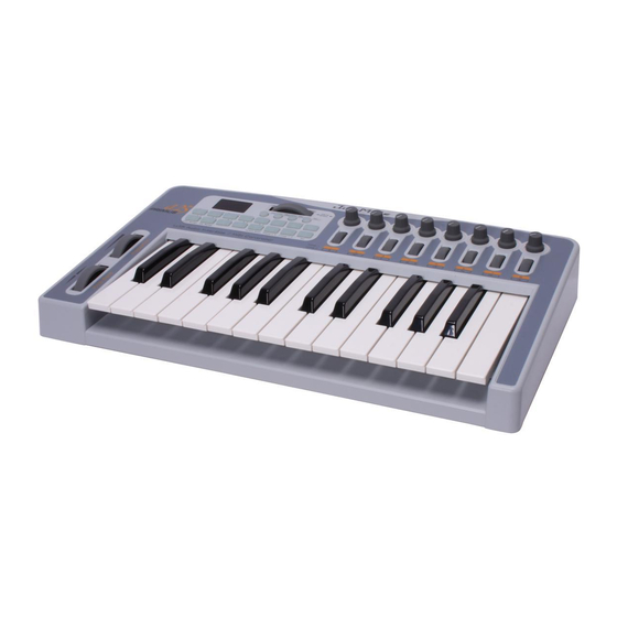
DETAIL OPERATION Top Panel Pitch Bend Wheel Modulation Wheel 3 Digit 7-segment LED Display Function Keypads Octave Selectors Assignable Data Wheel Decrease and Increase Keys 8 Assignable MIDI Controller Knobs 8 Assignable MIDI Controller Encoders Rear Panel Power Switch 9V Power Input USB 2.0 Bus Powered MIDI Input and Output Sustain Pedal... -
Page 6: Connections
6. Connect the PRIMUS a25 to your equipments (mixer, monitoring system, MIC, instruments, etc.) GETTING STARTED GUIDE This guide is intended as steps of using PRIMUS a25 on your computer. We recommend you follow next instructions. Install the driver 1. Insert included installation CD into CD-ROM in your computer. -
Page 7: Install The Bundled Demo Software
Install the bundled DEMO software Install bundled software in installation CD and configure the PRIMUS a25 in your application software. OPERATION Control Panel Digital Input gain: This control allows you to adjust input gain up to +24dB. Input selector: You can select the input type among ‘MIC’, ‘Line’ and ‘Hi-z’. -
Page 8: Function Charts
Function Charts <Function Keypad> How to see the function chart Steps The sequence by pressing the corresponded button in function keypad. Operating Operating functions by pressing the button in function keypad. LED display LED display shows status of operation. Function key’s light Status of the function key’s light. - Page 9 1) Channel: The [Channel] button allows you to select the transmitting channel for your keyboard. -Global Mode Steps Operating LED display Function key’s light A.25 [Function] [Function] blink [Channel] [Function] blink [Number] (1~16) [Function] blink [Enter] (1~16) blink once A.25 [Function] turn off -Assign Mode: Assigned controller’s channel.
- Page 10 3) Transpose: The [Transpose] button allows you to sets the transposition of your keyboard. Steps Operating LED display Function key’s light A.25 [Function] [Function] blink [Transpose] [Function] blink [Number] (-12~12) [Function] blink [Enter] (-12~12) blink once A.25 [Function] turn off 4) Controller Assign: The [Controller Assign] button allows you to define function of target knobs and wheel controller.
- Page 11 6) Panic: This button transmits all notes off, all sound off, and reset all controllers’ messages on all MIDI channels. Steps Operating LED display Function key’s light A.25 [Function] [Function] blink [Panic] [Function] turn off 7) Factory Reset: This button returns all data to their default setting. Steps Operating LED display...
- Page 12 -Expansion Mode: The combination of the two values, MSB and LSB, lets you specify a total of 16,384 different banks. Steps Operating LED display Function key’s light A.25 [Function] [Function] blink [Prog.Chg] [Function] turn on, [Prog.Chg] blink [Number] (0~127) [Function] turn on, [Prog.Chg] blink [Enter] (0~127) blink once [Function] turn on, [Prog.Chg] blink...
- Page 13 10) ESC: When you press [ESC] key, all setting goes back to previous setting. 11) Group 1/2: The preset bank selector. (Group 1: 1~8, Group 2: 9~16) Steps Operating LED display Function key’s light A.25 (Status: Group 1) [Group 1/2] A.25 (Status: Group 2) [Group 1/2] turn on [Group 1/2]...
- Page 14 13) DEC/-, INC/+, Data Wheel -Number input device: You can increase or decrease value of parameter by 1. When [DEC/-]’s LED and [INC/+]’s LED are turned on, [Data Wheel] has equal function. -[DATA Wheel] assignment: You can assign MIDI messages to [DATA Wheel]. Steps Operating LED display...
-
Page 15: Technical Specifications
TECHNICAL SPECIFICATIONS <Analog Audio> 1. Sample rate supports 44.1, 48, 88.2, 96 kHz 1) Input Type Line input 1,2 2) Connector Type 1/4" TS Phone jack 2. Analog Line Input 3) Peak level 0dBFS @ +6dBV 4) Programmable gain -64dB ~ +24dB (0.5dB step size) 5) Impedance About 10K Ohm 1) Input Type... - Page 16 3) Peak level +0dBV @ 0dBFS 4) Attenuation -64dB ~ +0dB(0.5dB step size) 5) Impedance Less than 30 Ohm 1) Output Type Headphone amplifier 2) Connector Type 1/4" TRS(stereo) Phone jack 6. Headphone Output 3)Load Impedance Range 32-300 ohm (for the best performance) 4) Output Power 60mW @ THD<0.1% ;...
-
Page 17: End User Warranty
SIMS Corp. will either replace the product, repair the product, or refund the purchase at its option. To obtain warranty service, the original purchaser or his authorized dealer must fill the support contact form at www.jammate.net. In the event repair is required, shipment to and from SIMS Corp. - Page 18 RAON Bldg. 9F, 92-8, Wonhyoro 2-ga, Yongsan-gu, Seoul, KOREA, 140-847 www.jammate.net www.simsaudio.com All features and specifications subject to change without notice. Parts of this manual are continually being updated. Please check our web site www.jammate.net occasionally for the most recent updated information.
-
Page 19: Appendix A - Midi Controller Information
APPENDIX A – MIDI Controller Information STANDARD CONTROLLER NUMBERS 00 Bank Select 22 Controller 22 44 Controller 44 01 Modulation 23 Controller 23 45 Controller 45 02 Breath Control 24 Controller 24 46 Controller 46 03 Controller 3 25 Controller 25 47 Controller 47 04 Foot Control 26 Controller 26... - Page 20 STANDARD CONTROLLER NUMBERS 64 Sustain Pedal 86 Controller 86 108 Controller 108 65 Portamento 87 Controller 87 109 Controller 109 66 Sostenuto 88 Controller 88 110 Controller 110 67 Soft Pedal 89 Controller 89 111 Controller 111 68 Legato Pedal 90 Controller 90 112 Controller 112 69 Hold 2...
-
Page 21: Appendix B - Preset Tables
APPENDIX B – Preset Tables * 4 presets optimized for bundled demo software and 1 useful preset (0~4) * 5 fully-editable internal user banks (5~9) * When you use the preset2 and preset3, you must load automation file for NI FM8 and NI Battery 3 in Bundled CD. Preset 0 (Default)-GM Mixer 1-8 (Group 1) Knob Channel... - Page 22 Preset 1 – NI Pro53 (Group 1) Knob Channel Controller Oscillator PolyMod Wheel Oscillator B Oscillator B PolyMod Function Master Tune Source Filt Mod LFO- Frequency Freq Fine Source Osc B Frequency Frequency Noise Mix Encoder Channel Controller Master Mixer Mixer Amplifier Amplifier...
- Page 23 Preset 2 – NI FM8 (Group 1) Knob Channel Controller Output Effects Arp.. Arp. Arp. Arp. Arp. Arp. Function Stereo Amount Tempo Note Length Shuffle Velocity Accent Width Encoder Channel Controller Master Output Output Pitch Function Master Tune Morph X Morph Y Volume Volume...
- Page 24 Preset 3 – NI Battery 3 (Group 1) Knob Channel Controller Cell 1 Cell 2 Cell 3 Cell 4 Cell 5 Cell 6 Cell 7 Cell 8 Function Pan Position Pan Position Pan Position Pan Position Pan Position Pan Position Pan Position Pan Position Encoder...
- Page 25 Preset 4 – NI B4II (Group 1) Knob Channel Controller Vibrato Function Volume Bass Treble Vibrato Mix Key Click Leakage Depth Encoder Channel Controller Lower Lower Lower Lower Lower Lower Lower Lower Function Drawbar Drawbar 5- Drawbar Drawbar Drawbar 2- Drawbar Drawbar 1- Drawbar 1-...
Need help?
Do you have a question about the PRIMUS a25 and is the answer not in the manual?
Questions and answers