Table of Contents

Related Manuals for Panasonic DMR-ES45VP


Summary of Contents for Panasonic DMR-ES45VP
-
Page 1: Dvd Recorder
ORDER NO.VR0603003CE DVD Recorder DMR-ES45VP DMR-ES46VP Vol. 1 Colour (S).......Silver Type © 2006 Matsushita Electric Industrial Co., Ltd. All rights reserved. Unauthorized copying distribution is a violation of law. -
Page 2: Table Of Contents
DMR-ES45VP / DMR-ES46VP CONTENTS Page Page 1 Safety Precaution 12.4. Analog Timer Block Diagram 1.1. General guidelines 12.5. System Control & Servo Block Diagram 1.2. Caution for fuse replacement 12.6. HDMI Block Diagram 2 Warning 13 Schematic Diagram 2.1. Prevention of Electrostatic Discharge (ESD) to 13.1. - Page 3 DMR-ES45VP / DMR-ES46VP 14.1. Power & Digital I/F P.C.B. 15.1. Abbreviations 14.2. Main P.C.B. 16 Appendix for Schematic Diagram 14.3. HDMI P.C.B. 16.1. Voltage and Waveform Chart 14.4. SD Card/DV Jack P.C.B. 17 Parts and Exploded Views 14.5. Front (L) P.C.B., Front (R) P.C.B.
-
Page 4: Safety Precaution
DMR-ES45VP / DMR-ES46VP 1 Safety Precaution 1.1. General guidelines 1. When servicing, observe the original lead dress. If a short circuit is found, replace all parts which have been overheated or damaged by the short circuit. 2. After servicing, see to it that all the protective devices such as insulation barriers, insulation papers shields are properly installed. -
Page 5: Warning
DMR-ES45VP / DMR-ES46VP 2 Warning 2.1. Prevention of Electrostatic Discharge (ESD) to Electrostatic Sensitive (ES) Devices Some semiconductor (solid state) devices can be damaged easily by static electricity. Such components commonly are called Electrostatic Sensitive (ES) Devices. Examples of typical ES devices are integrated circuits and some field-effect transistor-sand semiconductor "chip"... -
Page 6: Precaution Of Laser Diode
DMR-ES45VP / DMR-ES46VP 2.2. Precaution of Laser Diode... -
Page 7: Service Caution Based On Legal Restrictions
DMR-ES45VP / DMR-ES46VP 2.3. Service caution based on legal restrictions 2.3.1. General description about Lead Free Solder (PbF) The lead free solder has been used in the mounting process of all electrical components on the printed circuit boards used for this equipment in considering the globally environmental conservation. -
Page 8: Service Navigation
DMR-ES45VP / DMR-ES46VP 3 Service Navigation 3.1. Service Information... -
Page 9: Specifications
DMR-ES45VP / DMR-ES46VP 4 Specifications... -
Page 10: Features
DMR-ES45VP / DMR-ES46VP 5 Features 5.1. HDAVI Control (HDMI Link) Pin Name Linked operations by HDAVI Control (HDMI Link) 5.1.1. What is HDMI HDMI is abbreviation of [High-Definition Multimedia Interface], and is digital interface standard for next generation TV corresponding to follows. - Page 11 DMR-ES45VP / DMR-ES46VP (2) Seamless GUI 1. Automatic switching to DIGA functions from VIErA functions When [operate DIGA] of VIErA functions is selected, (3) Remote Control Operation input of VIErA is switched to DIGA input automatically Function that operate DIGA by VIErA remote controller and it displays DIGA functions.
- Page 12 DMR-ES45VP / DMR-ES46VP pressed, VIErA POWER ON/ Input switch/ audio mute is set automatically, and audio sound is output from speaker connected amp. (5) Timer Recording (Reservation Recording) When select [Reserve] of TV GUIDE of VIErA, Reservation information is transmitted by way of HDMI (HDAVI Control), and reservation registration of DIGA is done.
-
Page 13: Location Of Controls And Components
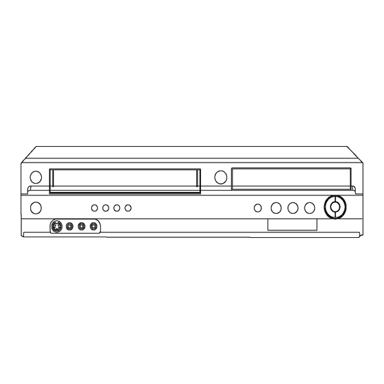
DMR-ES45VP / DMR-ES46VP 6 Location of Controls and Components 6.1. Each Buttons... - Page 14 DMR-ES45VP / DMR-ES46VP...
-
Page 15: Operation Instructions
DMR-ES45VP / DMR-ES46VP 7 Operation Instructions 7.1. (DVD) Taking out the Disc from RAM-Drive Unit when the Disc cannot be ejected by OPEN/CLOSE button 7.1.1. (DVD) Forcible Disc Eject 7.1.1.1. (DVD) When the power can be turned off. 1. Turn off the power and press [STOP], [CH UP] keys on the front panel simultaneously for 5 seconds. -
Page 16: Vhs) Removing Cassette Tape Manually
DMR-ES45VP / DMR-ES46VP 7.2. (VHS) Removing Cassette Tape manually When the cassette tape could not be uninstalled from an electrical malfunction, there are 2 ways to remove a cassette tape. 7.2.1. (VHS) Removal by compulsory unloading. If Service Mode can be activated when the power can not be turned on, this operation is able. - Page 17 DMR-ES45VP / DMR-ES46VP 3. Rotate the Main Cam Gear counter-clockwise until just before the unloading will be completed as shown below. . 4. Rotate the Capstan Motor clockwise to remove the slack tape as shown below. 5. Rotate the Main Cam Gear counter-clockwise again to remove the cassette-tape as shown below.
-
Page 18: Service Mode
DMR-ES45VP / DMR-ES46VP 8 Service Mode 8.1. (DVD) Self-Diagnosis and Special Mode Setting 8.1.1. (DVD) Self-Diagnosis Functions Self-Diagnosis Function provides information for errors to service personnel by “Self-Diagnosis Display” when any error has occurred. U**, H** and F** are stored in memory and held. - Page 19 DMR-ES45VP / DMR-ES46VP Error Code Diagnosis contents Description Monitor Display Automatic FL display UNSUPPO Unsupported disc error *An unsupported format disc was played, “This disc although the drive starts normally. incompatible.” *The data format is not supported, although the media type is supported.
- Page 20 DMR-ES45VP / DMR-ES46VP Item FL display Key operation Mode name Description Front Key Forced power-off When the power button is not effective while Display in P-off mode. Press [POWER] key over than 10 power is ON, turn off the power forcibly.
- Page 21 DMR-ES45VP / DMR-ES46VP 8.1.3. (DVD) Service Modes at a glance Service mode setting: While the power is off, press [STOP], [VHS to DVD DUBBING] and [OPEN / CLOSE] simultaneously for five seconds (OPERATION SELECT should be set to DVD). Item...
- Page 22 DMR-ES45VP / DMR-ES46VP Item FL display Key operation Mode name Description (Remote controller key) I/P Switch Switch Interlace and Progressive in EE mode. Initial mode is Interlace Press [1] [4] in I/P Switch mode. *Initial setting is “Interlace”. *I/P are switched alternately.
- Page 23 DMR-ES45VP / DMR-ES46VP Item FL display Key operation Mode name Description (Remote controller key) RAM Drive Last Error RAM Drive error code display. 1. Error Number is displayed for 5 Press [4] [2] in service mode. *For details about the drive error code, refer seconds.
- Page 24 DMR-ES45VP / DMR-ES46VP Item FL display Key operation Mode name Description (Remote controller key) Front connection Press all front keys and check the connection Press [5] [4] in service mode. inspection between Main P.C.B. and Front key Switches. (1) Each time a key is pressed, segment turned on increases one by one.
- Page 25 DMR-ES45VP / DMR-ES46VP Item FL display Key operation Mode name Description (Remote controller key) Tray OPEN/CLOSE Test The RAM drive tray is opened and closed Press [9] [1] in service mode repeatedly. *When releasing this mode, press the [POWER] button of Remote Controller more than 10 seconds.
-
Page 26: Vhs) Self-Diagnosis And Special Mode Setting
DMR-ES45VP / DMR-ES46VP 8.2. (VHS) Self-Diagnosis and Special Mode Setting 8.2.1. (VHS) Self-Diagnosis Functions This model has a self-diagnosis and display function. If the VHS section detects trouble during installation or during use, one of the following Error Codes will automatically appear in the display on VHS side. Error Codes are displayed in the form of a single English letter followed by two numbers, as for example "H01". - Page 27 DMR-ES45VP / DMR-ES46VP 8.2.2. (VHS) Special Modes Setting Item FL display Key operation Mode name Description Front Key Tracking Center Tape Tracking is adjusted to center No display. During PLAYBACK, press [CH UP] FIX position. DOWN] keys simultaneously. VHS Service Mode...
- Page 28 DMR-ES45VP / DMR-ES46VP Service Contents Contents of Indication on minute Contents of Indication on second Remarks Number Indication for the Mechanism position Ordering for the Motors There are next conditions in this inner data (Real time) (Real time) mode for enable the mechanism...
- Page 29 DMR-ES45VP / DMR-ES46VP 8.2.4.2. (VHS) Condition for clearing the self-diagnosis history 1. A case of that press the FF key and the EJECT key simultaneously over 5 seconds. 8.2.4.3. (VHS) Indication of the self-diagnosis history. 1. The self-diagnosis histories and its supplementary data could be indicated on the FIP with Service mode of number from 3 to 2.
- Page 30 DMR-ES45VP / DMR-ES46VP <Supplementary Data 4> (LM Information) Result of request of driving Loading Motor. Display Description There was no change of mechanism position. (Loading Motor was OFF) There was some change of mechanism position. (Loading Motor was ON) 8.2.5.
- Page 31 DMR-ES45VP / DMR-ES46VP Tape Type The aim of Tape position between the starting edge and the finishing edge 60 min. or less type (Large Hub) The Tape position is divided into 6 stages between the Tape beginning edge: "A " and the Tape end edge: "5".
-
Page 32: Service Fixture & Tools
DMR-ES45VP / DMR-ES46VP 9 Service Fixture & Tools (For DVD) Part Number Description Compatibility RFKZ0168 Extension Cable (Power & Digital I/F P.C.B. - FAN / 3 Pin) Same as E50 / ES30V / ES40V Series RFKZ0327 Extension Cable (Main P.C.B. - Power & Digital I/F P.C.B. / 15 Pin / 40 mm) Same as ES40V Series RFKZ0240 Extension Cable (Main P.C.B. -
Page 33: Assembling And Disassembling
DMR-ES45VP / DMR-ES46VP 10 Assembling and Disassembling 10.1. Disassembly Flow Chart The following chart is the procedure for disassembling the casing and inside parts for internal inspection when carrying out the servicing. To assemble the unit, reverse the steps shown in the chart below. -
Page 34: Positions
DMR-ES45VP / DMR-ES46VP 10.2. P.C.B. Positions... -
Page 35: Caution With Inserting Cassette Tape When Disassembling The Unit
DMR-ES45VP / DMR-ES46VP 10.3. Caution with inserting cassette tape when disassembling the unit Note1: For description of the disassembling procedure, see the section 10.4. Note2: Video Cassette might not enter when a strong lighting is applied to VHS Mechanism when Video Cassette is inserted. Please... -
Page 36: Top Case
DMR-ES45VP / DMR-ES46VP 10.4. Top Case 10.5. Front Panel 1. Remove the 4 Screws (A) and 3 Screws (B). 1. Remove one screw (A). 2. Slide Top Case rearward and open the both ends at rear 2. Unlock tab (A) and tab (B) simultaneously. -
Page 37: Front (L) P.c.b. & Front (R)
DMR-ES45VP / DMR-ES46VP Note: 10.7. RAM / Digital P.C.B. Module When attaching Front Panel, in order to hook Cassette Door Opener Lever to Cassette Door, push up cassette door in the direction of arrow and insert a front panel. 1. Remove 3 Screws (A). - Page 38 DMR-ES45VP / DMR-ES46VP Note: 3. Put Digital P.C.B. on RAM Drive and remove RAM/Digital RAM/Digital P.C.B. Module as service part has no heat sink P.C.B. Module. unit. Before returning to customer, heat sink unit should be installed on Digital P.C.B..
-
Page 39: Sd Card/Dv Jack P.c.b
DMR-ES45VP / DMR-ES46VP 10.8. SD Card/DV Jack P.C.B. 10.9.1. Caution for attaching VTR Mechanism Unit 1. Remove 7 Screws (A). 2. Remove SD Card/DV Jack P.C.B. with Digital Angle. 1. Attach VTR Mechanism Unit so that Boss of Position SW is put into long hole of Main Cam Gear, refer to Fig. -
Page 40: Rear Panel & Fan Motor
DMR-ES45VP / DMR-ES46VP 10.10. Rear Panel & Fan Motor 10.11. HDMI P.C.B. 1. Disconnect FFC. 10.10.1. Rear Panel with Fan Motor 2. Pull up HDMI P.C.B. for the direction of arrow. 1. Disconnect Fan Connector. 2. Remove 7 Screws (A) and 1 Screw (B). -
Page 41: Power & Digital I/F P.c.b
DMR-ES45VP / DMR-ES46VP 10.12. Power & Digital I/F P.C.B. 10.13. Main P.C.B. 1. Disconnect 5 Connectors (A). 1. Disconnect 5 Connectors. 2. Remove the 2 Screws (A). 2. Remove 2 Screws (A) and remove Main P.C.B. 3. Remove Power & Digital I/F P.C.B. -
Page 42: Measurements And Adjustments
DMR-ES45VP / DMR-ES46VP 11 Measurements and Adjustments 11.1. Service Positions Note: For description of the disassembling procedure, see the section 10. 11.1.1. Checking and Repairing of Power & Digital I/F P.C.B. - Page 43 DMR-ES45VP / DMR-ES46VP 11.1.2. Checking and Repairing of Main P.C.B.
- Page 44 DMR-ES45VP / DMR-ES46VP 11.1.3. Checking and Repairing of RAM / Digital P.C.B. Module...
-
Page 45: Caution For Replacing Parts
DMR-ES45VP / DMR-ES46VP 11.2. Caution for Replacing Parts 11.2.1. Notice for replacing parts of VHS Mechanism 11.2.1.1. Regarding change of parts of VHS mechanism 11.2.2. Notice for Replacing Capstan Motor... - Page 46 DMR-ES45VP / DMR-ES46VP 11.2.3. Items that should be done after replacing parts...
- Page 47 DMR-ES45VP / DMR-ES46VP...
-
Page 48: Standard Inspection Specifications After Making Repairs
No abnormality should be seen in the picture, sound or operation. Perform auto recording and playback for one minute using the RAM No abnormality should be seen in the picture, sound or operation. *Panasonic DVD-RAM disc should be used when recording and disc. playback. -
Page 49: Block Diagram
DMR-ES45VP / DMR-ES46VP 12 Block Diagram 12.1. Power Supply Block Diagram VA11101,L11101 L11102 D11101,C11108 T11101 X SW+12.5V SW TRANSFORMER AC SOCKET P11101 F11101 SURGE RECTIFIER SUPPRESSOR SURGE ABSORBER MECHA+12.5V D11210 P31903 P6003 MAIN P.C.B. IC11201 15,16 IC2501- (SWITCHING IC) Q11101... - Page 50 DMR-ES45VP / DMR-ES46VP IC4801 (REG.+9V) D +3.8V P37101 P9001 60,62 X SW +12.5V P31902 P6004 X SW +12.5V IC45001 V IN V OUT IC3701- (REG.AU +5V) DIGITAL P.C.B. ON/OFF AU +5V P37101 P9001 V IN V OUT 5 JC POWER ON...
-
Page 51: Analog Video Block Diagram
DMR-ES45VP / DMR-ES46VP 12.2. Analog Video Block Diagram JK3902 REAR A/V OUT JACK IC3701 (VIDEO I/O PROCESSOR) CPN V OUT VIDEO C-SW C75 OUT CPN Y OUT DVD C IN P59001 P37101 P31902 P6004 C OUT DM 6.7M S-VIDEO C75 SAG... - Page 52 DMR-ES45VP / DMR-ES46VP :DVD VIDEO EE SIGNAL :REC SIGNAL :PB SIGNAL IC3001 (AUDIO/VIDEO SIGNAL PROCESSOR) TU7401 2MHz U/V TUNER PACK TW3001 VIDEO ENVE SQUELCH VIDEO OUT -6dB -4dB SYSTEM CONTROL SECTION Q3004 CLEAR OSD V IN SQUELCH V-AMP SYNC IC6001-...
-
Page 53: Analog Audio Block Diagram
DMR-ES45VP / DMR-ES46VP 12.3. Analog Audio Block Diagram DVD AUDIO SIGNAL AUDIO MAIN SIGNAL PATH IN REC MODE AUDIO MAIN SIGNAL PATH IN PLAYBACK MODE IC4501 IC3001 FROM (AUDIO PROCESSOR) (AUDIO PROCESSOR) Q4001, D.REC SYSTEM QR4001 Q4002 IC6001- CONTROL SECTION... -
Page 54: Analog Timer Block Diagram
DMR-ES45VP / DMR-ES46VP 12.4. Analog Timer Block Diagram IC7501 (TIMER CPU) MAIN P.C.B. DP7501 FRONT L P.C.B. Q7501 FROM P31905 P6001 < OPERATION KEY > DISPLAY DIGITAL I/F P.C.B. DRIVE PS6001 PP4801 IC11720- FROM S7801 S7802 P31905 P6001 DIGITAL I/F P.C.B. -
Page 55: System Control & Servo Block Diagram
DMR-ES45VP / DMR-ES46VP 12.5. System Control & Servo Block Diagram MAIN P.C.B. IC0201 (CAPSTAN MOTOR DRIVE) IC6001 (SYSTEM CONTROL/SERVO) MECHA +12.3V P0201 P2571 TL2502 5V(D) 37 CAPSTAN CAP TL MOTOR COILS MOTOR DIFFERENTIAL TORQUE P0201 P2571 CURRENT LIMIT 12MHz IN 38... -
Page 56: Hdmi Block Diagram
DMR-ES45VP / DMR-ES46VP 12.6. HDMI Block Diagram IC56101 IC56103 IC56102 (HDMI TRANSMITTER) P55002 FP56101 P55002 FP56101 P55002 FP56101 P55002 FP56101 Video Color Space P55002 FP56101 Convertor Converter P55002 FP56101 P55002 FP56101 HDMI CONNECTOR P55002 FP56101 TX2P P56102 L56101 TX2M P56102... -
Page 57: Schematic Diagram
DMR-ES45VP / DMR-ES46VP 13 Schematic Diagram 13.1. Interconnection Schematic Diagram P6005 P31901 YOUT DM YOUT DM BPBOUT DM BPBOUT DM P2571 RPROUT DM RPROUT DM GPYOUT DM GPYOUT DM CAP R/F CAP R/F IECOUT IECOUT TU7401 I2C5 CK I2C5 CK... - Page 58 DMR-ES45VP / DMR-ES46VP FP50002 P37101 P59001 P50001 XINTP XINTP LDD VCC1 DR12V DR12V LDD VCC1 SCLK SCLK LDD VSS DR12V DR12V LDD VSS XINTM XINTM LDD ENABLE DRGND DRGND LDD GND2 SBPTM SBPTM LDD IINRD DRGND DRGND LDD IINW1 FP50003...
-
Page 59: Power Supply Section (Power & Digital I/F P.c.b.(1/2)) Schematic Diagram (P)
DMR-ES45VP / DMR-ES46VP 13.2. Power Supply Section (Power & Digital I/F P.C.B.(1/2)) Schematic Diagram (P) D11101 B0EBKT000008 Q11601 B1DHED000008 D11401 L11401 T11101 ZA11101 ZA11102 B0JCNG000003 LB11101 G4D2A0000267 G0A100H00025 MECHA_12R5V L11101 EYF52BCY EYF52BCY J0JKB0000003 DR12V #G0B832L00001 L11102 K3GE1ZA00010 L11601 K3GE1ZA00010 D11402... - Page 60 CURRENT THERMAL CNT. LIMITTER SHUTDOWN COMP UVLOcomp REFERENCE VOUT VREF PWON VREF/SS UVLOcomp VREF V5/PWON VREF/SS IC11201 Detail Block Diagram IC11301 Detail Block Diagram IC11601 Detail Block Diagram IC11720 Detail Block Diagram IC11801 Detail Block Diagram DMR-ES45VP/ES46VP IC-Detail Block Diagram...
-
Page 61: Digital I/F (1/4) Section (Power & Digital I/F P.c.b.(2/2))
DMR-ES45VP / DMR-ES46VP 13.3. Digital I/F (1/4) Section (Power & Digital I/F P.C.B.(2/2)) Schematic Diagram (IF) IC45001 LOCATION MAP X SW+6V SWITCHING REG. IC-DETAIL BLOCK DIAGRAM IC37001 FAN MOTOR DRIVE VOUT IC-DETAIL BLOCK DIAGRAM P:Power Supply Section:(Page: IF:Digital I/F Section:(Page: NOTE:DO NOT USE THE PART NUMBER SHOWN ON THIS DRAWING FOR ORDERRING. -
Page 62: Digital I/F (2/4) Section (Power & Digital I/F P.c.b.(2/2))
DMR-ES45VP / DMR-ES46VP 13.4. Digital I/F (2/4) Section (Power & Digital I/F P.C.B.(2/2)) Schematic Diagram (IF) LOCATION MAP TO PP7701 FRONT(R) P.C.B. PS31901 K1KB12B00040 AD5V VHS_LED SD_LED DUB_LED DVD_LED KEY3 KEY2 KEY1 SST6V K45004 ERJ3GEY0R00V C45012 1000P C45011 K45003 1000P... -
Page 63: Digital I/F (3/4) Section (Power & Digital I/F P.c.b.(2/2))
DMR-ES45VP / DMR-ES46VP 13.5. Digital I/F (3/4) Section (Power & Digital I/F P.C.B.(2/2)) Schematic Diagram (IF) AA AB AC AD DIGITAL I/F SECTION (1/4) C35001 0.1[KB][22] TO P56101 HDMI P.C.B. R35001 P35001 HDMI_CONT K1KY10AA0107 R35002 HOT_PLUG X_SW6V R35003 HDMI_P3_ON_H D3R8V... -
Page 64: Digital I/F (4/4) Section (Power & Digital I/F P.c.b.(2/2)) Schematic Diagram (If)
DMR-ES45VP / DMR-ES46VP 13.6. Digital I/F (4/4) Section (Power & Digital I/F P.C.B.(2/2)) Schematic Diagram (IF) AE AF AG AH AI AJ AL AM AN AO AP AQ AR AS DIGITAL I/F SECTION (2/4) Q37506 R37515 47K Q37507 B1CFHC000003 R45001... -
Page 65: Video (1/4) Section (Main P.c.b.(1/4)) Schematic Diagram
DMR-ES45VP / DMR-ES46VP 13.7. Video (1/4) Section (Main P.C.B.(1/4)) Schematic Diagram Schematic Diagram (V) LOCATION MAP IC3002 JC +5V SWITCHING REG. Q4082 IC-DETAIL BLOCK DIAGRAM 2SD0602ARL V:Video Section:(Page: T4081 G2A472C00003 C4082 R4081 A:VHS Audio Section:(Page: 470P[KB] S:Syscon/Servo/Timer Section:(Page: I:I/O Tuner Section:(Page:... -
Page 66: Schematic Diagram (V)
DMR-ES45VP / DMR-ES46VP 13.8. Video (2/4) Section (Main P.C.B.(1/4)) Schematic Diagram Schematic Diagram (V) LOCATION MAP VEE0U97 C2099 680P K4081 0 R2099 6800 V:Video Section:(Page: A:VHS Audio Section:(Page: S:Syscon/Servo/Timer Section:(Page: I:I/O Tuner Section:(Page: NOTE:DO NOT USE THE PART NUMBER SHOWN ON THIS DRAWING FOR ORDERRING. -
Page 67: Video (3/4) Section (Main P.c.b.(1/4)) Schematic Diagram
DMR-ES45VP / DMR-ES46VP 13.9. Video (3/4) Section (Main P.C.B.(1/4)) Schematic Diagram Schematic Diagram (V) VIDEO SECTION (1/4) R3032 3900 R3023 K3003 VWJ0795=7.5 R3021 2200 1500 K3005 VWJ0795=12.5 R3022 3300 K3034 VWJ0795=12.5 K3004 R3031 OSD_VIDEO_IN Q3004 2SD1819A0L C3053 0.1[KB] LOCATION MAP... -
Page 68: Video (4/4) Section (Main P.c.b.(1/4)) Schematic Diagram Schematic Diagram (V)
DMR-ES45VP / DMR-ES46VP 13.10. Video (4/4) Section (Main P.C.B.(1/4)) Schematic Diagram Schematic Diagram (V) VIDEO SECTION (2/4) C3003 0.1[KB] R3013 C3029 ECA1HAKR47XB SW36 SW11 C3030 0.022[KB] L-SECAM L-SECAM L3002 270u C3005 SW35 C3031 0.033[KB] X3002 C3006 0.1[KB] SW13 #H0D357400067 SW25... -
Page 69: Vhs Audio Section (Main P.c.b.(2/4)) Schematic Diagram
DMR-ES45VP / DMR-ES46VP 13.11. VHS Audio Section (Main P.C.B.(2/4)) Schematic Diagram (A) R4507 R4513 4700 4700 QR4501 C4519 UNR521100L Q4501 R4504 2SB0710A0L L4503 820[D] 100u Q4502 B1AAGD000016 C4524 0.1[KB] (2SC1959YT2M) D4502 MAZ4056NHF C4520 (MA4056N-HTA) 6V22 A5VL4501 L4501 1R2u A_5V REF_GND... -
Page 70: Syscon/Servo/Timer (1/4) Section (Main P.c.b.(3/4))
DMR-ES45VP / DMR-ES46VP 13.12. Syscon/Servo/Timer (1/4) Section (Main P.C.B.(3/4)) Schematic Diagram (S) LOCATION MAP V:Video Section:(Page: NOTE:DO NOT USE THE PART NUMBER SHOWN ON THIS DRAWING FOR ORDERRING. THE CORRECT PART NUMBER IS SHOWN IN THE PARTS LIST,AND MAY BE A:VHS Audio Section:(Page: SLIGHTLYDIFFERNT OR AMENDED SINCE THIS DRAWING WAS PREPARED. -
Page 71: Schematic Diagram(S)
DMR-ES45VP / DMR-ES46VP 13.13. Syscon/Servo/Timer (2/4) Section (Main P.C.B.(3/4)) Schematic Diagram (S) LOCATION MAP REF_GND IECOUT D_GND GPYOUT_DM RPROUT_DM BPBOUT_DM YOUT_DM COUT_DM V_Y_IN_DM CPNC_IN_DM X_SW12R3V MIX_L_OUT_DM AU_GND MIX_R_OUT_DM I2C5DT I2C5CK UNREG_38V ADC_L ADC_R D7505 C7505 6V470[M] X_SW_5R8V R1511 R1512 T REEL... -
Page 72: Schematic Diagram(S)
DMR-ES45VP / DMR-ES46VP 13.14. Syscon/Servo/Timer (3/4) Section (Main P.C.B.(3/4)) Schematic Diagram (S) SYSCON/SERVO/ TIMER SECTION (1/4) IC6002 C7521 PFAIL C0EBH0000172 0.01 (PST3142NR) SAFETY TAB SW S1531 K0C111A00006 TL6002 TL6004 R7541 220[D] POS.SW3 TO PP4801 MODE SW POS.SW2 FRONT(L) P.C.B. D7507... -
Page 73: Syscon/Servo/Timer (4/4) Section (Main P.c.b.(3/4)) Schematic Diagram (S)
DMR-ES45VP / DMR-ES46VP 13.15. Syscon/Servo/Timer (4/4) Section (Main P.C.B.(3/4)) Schematic Diagram (S) AA AB AD AE AF AG AH AI AJ AK AN AO AP AQ SYSCON/SERVO/ TIMER SECTION (2/4) R1501 R1502 TEST2 C6012 TL6010 C6005 50V3R3[KS] QR6801 C6020 1000P[KB]... - Page 74 V-SW MUTE R CH C1 IN IIC BUS INTERFACE P-ON V-SW MUTE Y1 IN P-ON IC3701 Detail Block Diagram MUTE C/S DET1 IC4801 Detail Block Diagram IC7301 Detail Block Diagram TUNER IN IC7402 Detail Block Diagram DMR-ES45VP/ES46VP IC-Detail Block Diagram...
-
Page 75: I/O Tuner Section (1/4) (Main P.c.b.(4/4)) Schematic Diagram (I)
DMR-ES45VP / DMR-ES46VP 13.16. I/O Tuner Section (1/4) (Main P.C.B.(4/4)) Schematic Diagram (I) LOCATION MAP JK4801 K1U407B00004 DVD_R_OUT COM_R_OUT DVD_L_OUT COM_L_OUT DVD_V_OUT COM_V_OUT DVD_CPN_OUT QR4802 XN0121600L C4831 V:Video Section:(Page: A:VHS Audio Section:(Page: C4832 F2A0J470A599 S:Syscon/Servo/Timer Section:(Page: I:I/O Tuner Section:(Page: R4858... -
Page 76: Diagram (I)
DMR-ES45VP / DMR-ES46VP 13.17. I/O Tuner Section (2/4) (Main P.C.B.(4/4)) Schematic Diagram (I) LOCATION MAP COM_CPN_OUT LINE LINE LINE LINE IN1[R] IN3[R] IN1[L] IN3[L] L1 IN L3 IN CPN L1 IN CPN L3 IN C3918 R3928 NOTE:DO NOT USE THE PART NUMBER SHOWN ON THIS DRAWING FOR ORDERRING. -
Page 77: Diagram (I)
DMR-ES45VP / DMR-ES46VP 13.18. I/O Tuner Section (3/4) (Main P.C.B.(4/4)) Schematic Diagram (I) A/V I/O SECTION (1/4) R4812 R4852 R4814 R4848 R4818 R4810 K3710 0 R4820 CPNC_IN_DM R4808 L12_SWIDE_A K3904 0 OSD_V_OUT L7402 G0A100HA0023 X_SW_5R8V L1_IN_L L1_IN_R L2_IN_L L2_IN_R L3_H... -
Page 78: Diagram (I)
DMR-ES45VP / DMR-ES46VP 13.19. I/O Tuner Section (4/4) (Main P.C.B.(4/4)) Schematic Diagram (I) AK AL A/V I/O SECTION (2/4) R7410 0[22] R7411 0[22] LB7407 ERJ3GEY0R00V LB7403 ERJ3GEY0R00V IF OUT C7421 C7422 6V47 0.01 R7401 1K[D] C7401 IC7402 D7401 50V1 C0CBCDD00006... - Page 79 IC7503 RESET RESET IC-DETAIL BLOCK DIAGRAM IC-DETAIL BLOCK DIAGRAM VOUT Vref Vref IC2001 Detail Block Diagram IC2501 Detail Block Diagram IC6002 Detail Block Diagram IC6301 Detail Block Diagram IC7501 Detail Block Diagram IC7503 Detail Block Diagram DMR-ES45VP/ES46VP IC-Detail Block Diagram...
-
Page 80: Hdmi Schematic Diagram
DMR-ES45VP / DMR-ES46VP 13.20. HDMI Schematic Diagram IC56101 C0JBAZ002116 LB56102 FL56101 J0JHC0000032 1 2 C56101 R56139 R56151 G_R656_CK_C R656_0 1 2 1 2 LB56103 R56155 R56152 J0JHC0000032 FL56103 R656_6 R656_1 R56156 R56153 R656_5 R656_2 R56140 ERJ2GEJ8R2X R56144 ERJ2GEJ8R2X L56101 (HDMI CONNECTOR) - Page 81 AMSDI3 IC-DETAIL BLOCK DIAGRAM AMRX VOUT HSDA Configuration Authentication IIC I/F Register Key Exchange HSCL IC56107 INVERTER IC-DETAIL BLOCK DIAGRAM IC56103 Detail Block Diagram IC56104 Detail Block Diagram IC56105 Detail Block Diagram IC56107 Detail Block Diagram DMR-ES45VP/ES46VP IC-Detail Block Diagram...
-
Page 82: Sd Card/Dv Jack Schematic Diagram
DMR-ES45VP / DMR-ES46VP 13.21. SD Card/DV Jack Schematic Diagram R66806 SDAT2 SDAT3 R66805 P66802 SCMD R66804 K1MY20BA0049 R66802 SDAT0 CKF20 P66801 SDAT1 CKF19 DAT1 R66801 SDAT1 K1NA09E00075 SDAT0 CKF18 DAT0 CKF17 G_SCLK_B CKF16 CKE9 SDAT2 R66809 DAT2 CKF15 SCMD CKE1... -
Page 83: Front (R) Schematic Diagram
DMR-ES45VP / DMR-ES46VP 13.22. Front (R) Schematic Diagram OPEN/CLOSE 1500 R7704 R7714 R7703 R7707 1500 S7707 1500 2200 S7711 S7706 S7705 S7702 S7703 S7704 PLAY STOP SELECT R7705 R7706 R7708 R7715 IC7701 D7702 D7703 D7704 D7706 B3RAD0000122 B3ADA0000173 B3ACA0000273 B3ABA0000595... -
Page 84: Front (L) Schematic Diagram
DMR-ES45VP / DMR-ES46VP 13.23. Front (L) Schematic Diagram R7806 8200 R7801 3900 R7805 R7802 3900 2700 R7803 3900 R7804 2700 POWER EJECT S7810 S7802 S7806 S7813 CH UP CH DWN JK4600 K2HA307A0009 S7803 S7801 K2HA307A0011 S1 IN TO PS6001 MAIN P.C.B. -
Page 85: Printed Circuit Board
DMR-ES45VP / DMR-ES46VP 14 Printed Circuit Board 14.1. Power & Digital I/F P.C.B. 14.1.1. Power & Digital I/F P.C.B. Power & Digital I/F P.C.B. COLD DMR-ES45VP/ES46VP Power & Digital I/F P.C.B. (RFKBV0061B) - Page 86 DMR-ES45VP / DMR-ES46VP 14.1.2. Power & Digital I/F P.C.B. Address Information Digital I/F P.C.B. Integrated Circuit D11402 C31505 R11608 R45009 Surge Absorber C31506 IC11201 D11504 R11610 R45014 VA11101 D11505 C31507 R11701 R45015 IC11301 Fuse Holder D11602 C31508 R11702 R45016 IC11502...
-
Page 87: Main
DMR-ES45VP / DMR-ES46VP 14.2. Main P.C.B. 14.2.1. Main P.C.B. (1/4 Section) Location Map (FRONT) (REAR) DMR-ES45VP/ES46VP Main P.C.B. (VEPV0054BT) (1/4 Section) - Page 88 DMR-ES45VP / DMR-ES46VP 14.2.2. Main P.C.B. (2/4 Section) Location Map (FRONT) (REAR) DMR-ES45VP/ES46VP Main P.C.B. (VEPV0054BT) (2/4 Section)
- Page 89 DMR-ES45VP / DMR-ES46VP 14.2.3. Main P.C.B. (3/4 Section) Location Map (FRONT) (REAR) DMR-ES45VP/ES46VP Main P.C.B. (VEPV0054BT) (3/4 Section)
- Page 90 DMR-ES45VP / DMR-ES46VP 14.2.4. Main P.C.B. (4/4 Section) Location Map (FRONT) (REAR) DMR-ES45VP/ES46VP Main P.C.B. (VEPV0054BT) (4/4 Section)
- Page 91 DMR-ES45VP / DMR-ES46VP 14.2.5. Main P.C.B. Address Information Main P.C.B. Integrated Circuit TL7507 LB7412 C7405 R3914 R7531 C3707 C4804 R4852 IC1511 Connector LB7413 C3709 C7406 R3915 R4855 R7532 C4805 IC1512 JK3902 C7408 R3924 R7533 Filter C3710 C4806 R4856 IC2001 JK3903...
-
Page 92: Hdmi
DMR-ES45VP / DMR-ES46VP 14.3. HDMI P.C.B. HDMI P.C.B. (Foil Side) (Component Side) DMR-ES45VP/ES46VP DMR-ES45VP/ES46VP HDMI P.C.B. (VEP73137A) HDMI P.C.B. (VEP73137A) -
Page 93: Sd Card/Dv Jack P.c.b
DMR-ES45VP / DMR-ES46VP 14.4. SD Card/DV Jack P.C.B. SD Card / DV Jack P.C.B. DMR-ES45VP/ES46VP (FOIL SIDE) SD Card / DV Jack P.C.B. (FOIL SIDE) (VEP001P1A) (COMPONENT SIDE) DMR-ES45VP/ES46VP SD Card / DV Jack P.C.B. (COMPONENT SIDE) (VEP001P1A) -
Page 94: Front (L) P.c.b., Front (R) P.c.b
DMR-ES45VP / DMR-ES46VP 14.5. Front (L) P.C.B., Front (R) P.C.B. Front (L) P.C.B. Front (R) P.C.B. DMR-ES45VP/ES46VP Front (L) P.C.B. (VEP0057A) Front (R) P.C.B.(VEP0058B) -
Page 95: Miscellaneous
DMR-ES45VP / DMR-ES46VP 15 Miscellaneous INITIAL/LOGO ABBREVIATIONS ERROR TORQUE CONTROL ERROR TORQUE CONTROL 15.1. Abbreviations REFERENCE ENCSEL ENCODER SELECT ETMCLK EXTERNAL M CLOCK (81MHz/40.5MHz) 15.1.1. DVD ETSCLK EXTERNAL S CLOCK (54MHz) FBAL FOCUS BALANCE INITIAL/LOGO ABBREVIATIONS FCLK FRAME CLOCK A0~UP... - Page 96 DMR-ES45VP / DMR-ES46VP INITIAL/LOGO ABBREVIATIONS INITIAL/LOGO ABBREVIATIONS READ ENABLE VBLANK V BLANKING RFENV RF ENVELOPE COLLECTOR POWER SUPPLY RF PHASE DIFFERENCE OUTPUT VOLTAGE (CD-ROM) REGISTER SELECT VCDCONT VIDEO CD CONTROL (TRACKING RSEL RF POLARITY SELECT BALANCE) RESET DRAIN POWER SUPPLY VOLTAGE...
- Page 97 DMR-ES45VP / DMR-ES46VP 15.1.2. VHS 4.43 NTSC L 443NT [L] BILINGUAL BILINGUAL L A. COMP AUDIO COMPONENT SIGNAL BIL [L] BILINGUAL H BIL. [H] A. COMPO AUDIO COMPONENT SIGNAL AUDIO DUBBING PAUSE L BILINGUAL L BIL/M1 [L] A. D.P [L]...
- Page 98 DMR-ES45VP / DMR-ES46VP CYL GND CYLINDER GND FULL. E. 12V FULL ERASE 12V DELAIED FM RECORDING H D.F.M. REC [H] GND [A] GND (ANALOG) DELAIED FM RECORDING L D. FM REC [L] GND [TU] GND (TUNER) D. GND DIGITAL GND GND/N.
- Page 99 DMR-ES45VP / DMR-ES46VP POWER OFF H LINE IN [R] LINE INPUT (R) P-OFF [H] POWER OFF L LINE OUT [L] LINE OUTPUT (L) P-OFF [L] LINE OUT [R] LINE OUTPUT (R) P. FAIL POWER FAILURE DETECT LP H POWER OFF H LP [H] P.
- Page 100 DMR-ES45VP / DMR-ES46VP RF OUT RF OUTPUT SYSCON 5V SYSTEM CONTROL 5V RF Y RF LUMINANCE SIGNAL SYSTEM SYSTEM SW RF. Y. IN RF LUMINANCE SIGNAL INPUT T-PHOTO TAKE-UP PHOTO TRANSISTOR RF. Y. OUT RF LUMINANCE SIGNAL OUTPUT T-RL. PLS TAKE-UP REEL PULSE ROTAR.
-
Page 101: Appendix For Schematic Diagram
DMR-ES45VP / DMR-ES46VP 16 Appendix for Schematic Diagram 16.1. Voltage and Waveform Chart 16.1.1. Power & Digital I/F P.C.B. @4,,-6, @4,,.6, @4,,06- !"#$%&' ()*+ 56'- ,-'1 5//1 ,-'2 5-76 89:; 56'- ,-'1 5//1 ,-'2 5-76 <=)8 56'- ,-'1 5//1 ,-'2... - Page 102 DMR-ES45VP / DMR-ES46VP 16.1.2. Main P.C.B. @4,0,, @4,0,- @4-66, !"#$%&' ()*+ 89:; <=)8 !"#$%&' @4-06, ()*+ ,-'- ,1', ,1'- 89:; ,-'- ,1'- <=)8 ,-'- @4-06, !"#$%&' ()*+ ,-'- 89:; ,-'- <=)8 ,-'- @4.66, !"#$%&' ()*+ 89:; <=)8 @4.66, !"#$%&' ()*+ 89:;...
- Page 103 DMR-ES45VP / DMR-ES46VP @4/76, !"#$%&' ()*+ ,-'- 89:; ,-'- <=)8 ,-'- !"#$%&' @4166, ()*+ 89:; <=)8 @4166, !"#$%&' ()*+ 89:; <=)8 !"#$%&' @4166, ()*+ 89:; <=)8 @4166, !"#$%&' ()*+ 89:; <=)8 @4166, !"#$%&' ()*+ 89:; <=)8 @4166- @41.6, !"#$%&' ()*+ 89:;...
- Page 104 DMR-ES45VP / DMR-ES46VP ?,06, ?,06- ?.66, ?.66/ ?/66, !"#$%&' ()*+ > > > 5,3'/ ,6'/ 5-7', 89:; <=)8 !"#$%&' ?/66- ?/67- ?/67/ ?/67/ ?/06, > ()*+ > > > > 56'1 5,3'/ 5-7', ,-'/ ,-'. ,,'2 89:; ,-'/ ,-'. ,,'2 <=)8...
- Page 105 DMR-ES45VP / DMR-ES46VP 16.1.3. HDMI P.C.B. @401,6, !"#$%&' ()*+ 89:; <=)8 @401,6- !"#$%&' ()*+ 89:; <=)8 @401,6. !"#$%&' ()*+ 89:; <=)8 @401,6. !"#$%&' ()*+ 89:; <=)8 @401,6. !"#$%&' ()*+ 89:; <=)8 @401,6. !"#$%&' ()*+ 89:; <=)8 !"#$%&' @401,6. ()*+ 89:;...
- Page 106 DMR-ES45VP / DMR-ES46VP 16.1.5. P59001 Connector 80366, !"#$%&' ()*+ ,-'1 ,-'1 89:; ,-'1 ,-'1 <=)8 ,-'1 ,-'1 80366, !"#$%&' ()*+ 89:; <=)8 80366, !"#$%&' ()*+ ,-'/ ,-'/ ,-'/ ,-'/ ,-'/ 89:; ,-'/ ,-'/ ,-'/ ,-'/ ,-'/ <=)8 ,-'/ ,-'/ ,-'/...
-
Page 107: Waveform Chart
DMR-ES45VP / DMR-ES46VP 16.1.6. Waveform Chart IC6001-19 PLAY IC6001-18(TW2001) REC IC6001-50 REC/PLAY IC6001-52 REC/PLAY IC6001-79 FF/REW 5.0Vp-p (10msec.div.) 5.0Vp-p (5msec.div.) 2.2Vp-p (20usec.div.) 2.2Vp-p (20usec.div.) 5.0Vp-p (1msec.div.) IC6001-95 REC IC6001-86(TL2015) PLAY IC6001-90 REC IC6001-94 REC IC6001-80 FF/REW 0.7Vp-p (0.5msec.div.) 2.4Vp-p (10msec.div.) 5.0Vp-p (1msec.div.) - Page 108 DMR-ES45VP / DMR-ES46VP IC11201-9 STOP 300Vp-p (5usec.div) T11101-1 STOP T11101-4 STOP T11301-6 STOP T11301-8 STOP 10Vp-p (2msec.div) 36Vp-p (5usec.div) 300Vp-p (5usec.div) 25Vp-p (5usec.div) P59001-27,29 REC/PLAY P59001-17,19 REC/PLAY P59001-39 REC/PLAY P59001-43 REC/PLAY P59001-47 REC/PLAY 1.0Vp-p (1msec.div) 0.8Vp-p (1msec.div) 1.0Vp-p (20usec.div.) 0.8Vp-p (20usec.div.) 0.6Vp-p (20usec.div)
-
Page 109: Parts And Exploded Views
DMR-ES45VP / DMR-ES46VP 17 Parts and Exploded Views 17.1. Exploded Views 17.1.1. Casing Parts & Mechanism Section1... - Page 110 DMR-ES45VP / DMR-ES46VP 17.1.2. Casing Parts & Mechanism Section 2...
-
Page 111: Vhs Mechanism Section
DMR-ES45VP / DMR-ES46VP 17.1.3. VHS Mechanism Section... - Page 112 DMR-ES45VP / DMR-ES46VP 17.1.4. Packing & Accessories Section...
-
Page 113: Replacement Parts List
DMR-ES45VP / DMR-ES46VP 17.2. Replacement Parts List Ref. Part No. Part Name & Remarks Description C3008 ECA1HAK4R7XB 50V 4.7 Notes: C3009 F1H0J1050010 6.3V 1U *Important safety notice: C3010 F1H0J1050010 6.3V 1U C3011 F1H1C104A041 16V 0.1U Components identified mark have special... - Page 114 DMR-ES45VP / DMR-ES46VP Ref. Part No. Part Name & Remarks Ref. Part No. Part Name & Remarks Description Description C4005 ECEA0JKA220B 6.3V 22U C4836 ECA1CAK100XB 16V 10U C4006 ECA1HAK4R7XB 50V 4.7 C4837 ECA1HAK010XB 50V 1U C4007 ECJ1VB1H182K 50V 1800P C4840 F1H1C104A041 16V 0.1U...
- Page 115 DMR-ES45VP / DMR-ES46VP Ref. Part No. Part Name & Remarks Ref. Part No. Part Name & Remarks Description Description C7509 F1H1C104A008 16V 0.1U L3003 G0C270JA0019 COIL 27UH C7510 ECJ1VC1H180J 50V 18P L3004 G0C680JA0019 COIL C7511 ECJ1VC1H180J 50V 18P L3005 G0C270JA0019...
- Page 116 DMR-ES45VP / DMR-ES46VP Ref. Part No. Part Name & Remarks Ref. Part No. Part Name & Remarks Description Description QR4001 UNR511100L TRANSISTOR R3915 ERJ3GEYF750V 1/10W 75 QR4082 UNR521300L TRANSISTOR R3924 ERJ3GEYJ750V 1/10W 75 QR4501 UNR521100L TRANSISTOR R3926 ERJ3GEYJ102V 1/10W 1K...
- Page 117 DMR-ES45VP / DMR-ES46VP Ref. Part No. Part Name & Remarks Ref. Part No. Part Name & Remarks Description Description R4837 D0GB392JA007 1/10W 3.9K R7508 D0GB473JA041 1/10W 47K R4838 D0GB392JA007 1/10W 3.9K R7511 D0GB101JA007 1/10W 100 R4841 ERJ3GEYJ473V 1/10W 47K R7512...
- Page 118 DMR-ES45VP / DMR-ES46VP Ref. Part No. Part Name & Remarks Ref. Part No. Part Name & Remarks Description Description W734 ERJ3GEY0R00V 1/10W 0 W810 ERJ3GEY0R00V 1/10W 0 W735 ERJ8GEY0R00V 1/4W 0 W811 ERJ6GEY0R00V 1/8W 0 W736 ERJ8GEY0R00V 1/4W 0 W812...
- Page 119 DMR-ES45VP / DMR-ES46VP Ref. Part No. Part Name & Remarks Ref. Part No. Part Name & Remarks Description Description LB56111 J0JHC0000032 COIL C56001 ECJ0EC1H221J 50V 220P LB56112 J0JHC0000032 COIL C56101 F1G1A1040006 10V 0.1U LB56115 J0JHC0000032 COIL C56102 F1G1A1040006 10V 0.1U...
- Page 120 DMR-ES45VP / DMR-ES46VP Ref. Part No. Part Name & Remarks Ref. Part No. Part Name & Remarks Description Description R56158 ERJ2GEJ152X 1/16W 1.5K C11512 ECJ2VB1E104K 25V 0.1U R56159 ERJ2GEJ332X 1/16W 3.3K C11513 ECJ2VB1E473K 25V 0.047U R56160 ERJ2GEJ223X 1/16W 22K C11601...
- Page 121 DMR-ES45VP / DMR-ES46VP Ref. Part No. Part Name & Remarks Ref. Part No. Part Name & Remarks Description Description D11402 B0JCNG000003 DIODE LB37013 J0JKB0000032 FILTER D11504 MA2J11100L DIODE LB37014 J0JKB0000032 FILTER D11505 MA2J11100L DIODE LB45001 J0JCC0000103 COIL D11602 B0JCPD000021 DIODE...
- Page 122 DMR-ES45VP / DMR-ES46VP Ref. Part No. Part Name & Remarks Ref. Part No. Part Name & Remarks Description Description R11610 ERJ6GEYJ103V 1/8W 10K W305 ERJ3GEY0R00V 1/10W 0 R11701 ERJ6GEYJ391V 1/8W 390 W306 ERJ6GEY0R00V 1/8W 0 R11702 ERJ6GEYJ102V 1/8W 1K W307...
- Page 123 DMR-ES45VP / DMR-ES46VP Ref. Part No. Part Name & Remarks Ref. Part No. Part Name & Remarks Description Description RWJV0046 FFC(40P) R7703 D0GB152JA007 1/10W 1.5K RWJV0033 FFC(7P) R7704 D0GB152JA007 1/10W 1.5K RWJV0034 FFC(6P) R7705 D0GB391JA041 1/10W 390K VKC0295 PCB HOLDER...
- Page 124 DMR-ES45VP / DMR-ES46VP Ref. Part No. Part Name & Remarks Description EUR7659Y70 REMOTE CONTROL ASS’Y A1-1 UR76EC5903A BATTERY COVER VFA0461 AC CORD K2KA6BA00003 AV CORD K2KZ2BA00001 RF COAXIAL CABLE VPK2737 ACCESSORY CASE RQTV0141-1 OPERATING (IA) INSTRUCTIONS RQCAV0009-1 SET-UP GUIDE ES45VP...
Need help?
Do you have a question about the DMR-ES45VP and is the answer not in the manual?
Questions and answers