Table of Contents
Advertisement
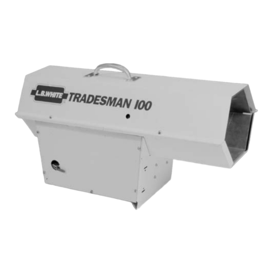
Owner's Manual and Instructions
Tradesman® Construction Heater
MODELS
OUTPUT (Btuh)
FUEL
Propane Vapor
CP100
100,000
Withdrawal
Certification by:
Congratulations!
You have purchased the finest construction heater available.
Your new L.B. White heater incorporates the benefits from the most experienced
manufacturer of heating products using state-of-the-art technology.
We, at L.B. White, thank you for your confidence in our products and
welcome any suggestions or comments you may have...call us, toll-free,
at 1-800-345-7200.
ATTENTION ALL USERS
This heater has been tested and evaluated by CSA International in accordance with
Standard ANSI Z83.7 CSA 2.14 and is listed and approved as a direct gas-fired
forced-air construction heater for the heating of buildings under construction,
alteration or repair. If you are considering using this product for any application
other than its intended use, then please contact your fuel gas supplier, or the
L.B. White Co., Inc.
150-21834-A
Advertisement
Table of Contents

Related Manuals for L.B. White Tradesman CP100

Summary of Contents for L.B. White Tradesman CP100
- Page 1 Your new L.B. White heater incorporates the benefits from the most experienced manufacturer of heating products using state-of-the-art technology. We, at L.B. White, thank you for your confidence in our products and welcome any suggestions or comments you may have...call us, toll-free, at 1-800-345-7200.
- Page 3 Save this Owner’s Manual for future use and reference. Owner’s Manuals and replacement labels are available at no charge. For assistance, contact L.B. White at 800-345-7200. WARNING Proper gas supply pressure must be provided to the inlet of the heater.
-
Page 4: Table Of Contents
This manual will instruct you in the operation and care of The L.B. White Co., Inc. has a policy of continuous product your unit. Completely review this manual so that you fully improvement. -
Page 5: Heater Specifications
Heater Specifications M M o o d d e e l l CP100 SPECIFICATIONS Propane Fuel Type Maximum Input (BTUH) 100,000 Minimum Input (BTUH) 50,000 Ventilation Air Required 350 CFM to Support Combustion Inlet Gas Supply 11 in. W.C. MAX. Pressure Acceptable at the Inlet of the Heater for Purpose... -
Page 6: Safety Precautions
Safety Precautions WARNING Asphyxiation H H azard Do not use this heater for heating human living Refer to the specification section of the heater’s quarters. Owner’s Manual, heater dataplate, or contact the L.B. White Company to determine combustion air ventilation Do not use in unventilated areas. - Page 7 100 pound by the Commonwealth of Massachusetts. cylinders. 2. All installations and applications of L.B. White heaters 12. The hose assembly shall be visually inspected on an must meet all relevant local, state and national annual basis.
-
Page 8: Set-Up Instructions
8. This heater is provided with a pre-set single-stage agency for repair or replacement. regulator and a gas hose, as specified by L.B. White Co., of proper length, diameter, and construction. 2. Make sure the heater is properly positioned before Make sure these critical components are installed to use. -
Page 9: Carrying Handle Assembly
CARRYING HANDLE ASSEMBLY 1. Fasten the carrying handle to the heater case top FIG. 1 using the four (4) sheet metal screws provided. HANDLE 2. The handle may also be fastened to the side of the case top for stacking purposes during storage. SCREW CAUTION Do not stack the heaters more than two high during... -
Page 10: Start-Up Instructions
Start-Up Instructions Follow steps 1 - 5 on initial start-up. For normal start-up, FIG. 3 follow steps 2 and 3. Open all manual fuel supply valves and check for gas leaks using approved leak detectors. Connect the heater’s electrical cord to an approved electrical supply. -
Page 11: Variable Heat Output
Variable Heat Output 1. This heater has a heat adjustment valve for varying parallel to the gas flow, the valve is completely open heat output located on the side of the heater. THIS IS to deliver maximum heat output. (Refer to Fig. 4.) NOT A MANUAL GAS SHUT OFF VALVE. -
Page 12: Cleaning Instructions
Markings are available at no cost by contacting the L.B. White Co. 2. The a a ppliance a a rea s s hall b b e k k ept c c lear a a nd f f ree f f rom combustible m m aterials, g g asoline, a a nd o o ther 4. -
Page 13: Service Instructions
Service Instructions MOTOR AND FAN ASSEMBLY 9 1. Disconnect the heater from its electrical supply. FIG. 6 2. Close all fuel supply valves to the inlet of the heater. MOTOR 3. Remove the case top and either side panel. 4. Disconnect the motor leads. BOLT 5. -
Page 14: Burner Orifice
BURNER ORIFICE 8. Reconnect the heater to its electrical supply and open CAUTION the fuel supply valves to the heater. Allow the heater to cool before servicing. 9. Start the heater and check for proper operation. Leak check the compression sleeve and orifice 1. -
Page 15: Backflash Switch
3. Remove the cap on the underside of the control valve. 4. Connect a pressure gauge at this point, capable of reading up to 35 in. W.C. (L.B. White gauge part number 00764.) 5. Reconnect the heater to its electrical supply and open the fuel supply valves to the heater. -
Page 16: Testing The Backflash Switch
TESTING THE BACKFLASH SWITCH The backflash switch is an auto reset temperature switch. FIG. 12 The switch should be tested at least once a year, preferably when the heater is given a thorough cleaning. BACKFLASH SWITCH 1. Remove the switch with bracket from the heater. 2. -
Page 17: Troubleshooting Guide
Troubleshooting Guide READ THIS ENTIRE SECTION BEFORE To effectively use these flow charts, you must first identify BEGINNING TO TROUBLESHOOT PROBLEMS. the problem. The problems are numbered sequentially, along with a brief explanation of each problem. Start at the diamond closest to the identified problem and proceed with The following troubleshooting guide provides systematic each step, performing whatever tests are suggested. -
Page 22: Electrical Connection And Ladder Diagram
Electrical Connection and Ladder Diagram CAUTION Always refer to the heater’s electrical connection diagram when servicing to avoid wiring errors and heater malfunction. Check for proper operation after servicing. CAUTION--REFER TO THE HEATER'S ELECTRICAL CONNECTION DIAGRAM WHEN SERVICING TO AVOID WIRING ERRORS AND HEATER MALFUNCTION. -
Page 23: Heater Component Function
Heater Component Function Backflash Switch Motor Safety device which is used to break an electrical circuit in Converts electrical energy into mechanical energy. It is used the event of an overheat condition. in conjunction with the fan blade to pull air into the burner for combustion and to circulate the air for heating purposes. -
Page 24: Parts Identification
Parts Identification PARTS SCHEMATIC... -
Page 25: Parts List
PARTS LIST Item Description Part N N umber Regulator, Single Stage 21856 Hose, 3/8 in. ID x 10 ft. 21841 Adapter, Hose 06654 Cord, Power 09139 Panel, Left with Marking 21795 Case, Back 21794 Panel, Right 21796 Case, Front 21798 Control, Ignition 21813 Relay with Clips and Screws... -
Page 26: Warranty Policy
L.B. White Co., Inc. will at its option, repair qualification. If neither is available, the warranty period will be 12 months from date of shipment from L B.
Need help?
Do you have a question about the Tradesman CP100 and is the answer not in the manual?
Questions and answers