
Related Manuals for Aurora 442


Summary of Contents for Aurora 442
- Page 1 INSTALLATION, MODEL 442 OPERATION AND MAINTENANCE HORIZONTAL SPLIT CASE INSTRUCTIONS & MODEL 492 SPLIT CASE FIRE PUMP...
-
Page 2: Table Of Contents
TABLE OF CONTENTS PAGE i TOPIC PAGE PUMP IDENTIFICATION ........STORAGE OF PUMPS . -
Page 4: Pump Identification
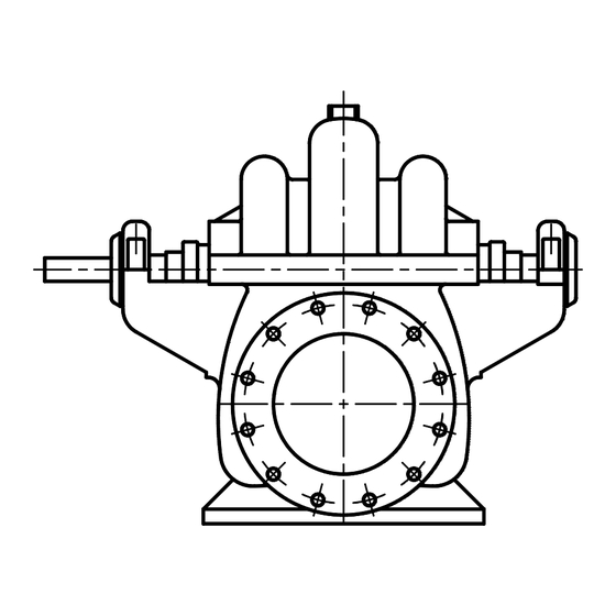
442 & 492 SPLIT CASE PUMPS Your Aurora Model 442 & 492 is a Split Case Pump, meaning the casing is split along the horizontal centerline. This new compact design, with its shorter bearing span, has less deflection under hydraulic load which results in less wear on the sleeves, bearings and packing. -
Page 5: Storage Of Pumps
STORAGE OF PUMPS AND CAUTION NOTES PAGE 2 THESE INSTRUCTIONS APPLY TO THE PUMP ONLY. THEY ARE INTENDED TO BE GENERAL AND NOT SPECIFIC. IF YOUR OPERATING CONDITIONS EVER CHANGE, ALWAYS REFER TO THE FACTORY FOR REAPPLICATION. ALWAYS REFER TO THE MANUALS PROVIDED BY MANUFACTURERS OF THE OTHER EQUIPMENT FOR THEIR SEPARATE INSTRUCTIONS. -
Page 6: Introduction
INTRODUCTION AND INSTALLATION PAGE 3 INTRODUCTION This manual contains information that is the result of carefully conducted engineering and research efforts. It is designed to supply adequate instructions for the safe and efficient installation, operation maintenance of your pump. Failure or neglect to properly install, operate or maintain your pump may result in personal injury, property damage or unnecessary damage to the pump. -
Page 7: Minimum Submergence Of Suction Pipe And Pit Design
INSTALLATION (continued) PAGE 4 MINIMUM SUBMERGENCE OF SUCTION PIPE AND PIT DESIGN For installations where the pump draws fluid from a sump, the hydraulic characteristics of the pump, the suction inlet submergence and NPSH must be considered. Generally, it is required that an evenly distributed flow of non-aerated water be supplied to the suction bell. -
Page 8: Grouting
INSTALLATION (continued) PAGE 5 GROUTING When the alignment is correct, the unit should be grouted using high-grade non-shrinking grout. The entire base should be filled with grout. Be sure to fill all gaps and voids. Allow the grout to fully cure before firmly tightening the foundation bolts. -
Page 9: Flexible Shaft Alignment
INSTALLATION (continued) PAGE 6 FIGURE 3 COUPLING ALIGNMENT FINAL COUPLING ALIGNMENT (continued) B. Check the angular alignment with a micrometer or caliper. Measure from the outside of one flange to the outside of the other at intervals around the periphery of the coupling. Determine the maximum and minimum dimensions. -
Page 10: Mechanical Seals
CAUTION: DRY OPERATION OF THE PUMP MAY CAUSE DAMAGE TO THE MECHANICAL SEAL AND IMPELLER. Model 442 pumps can be supplied with optional single face mechanical shaft seals. Mechanical seals are installed and adjusted in the factory and require no further adjustments in the field. -
Page 11: Operation
OPERATION PAGE 8 Because variations exist in both the equipment used with these pumps and in the particular installation of the pump and driver, specific operating instructions are not within the scope of this manual. However, there are general rules and practices that apply to all pump installations and operation. CAUTION: BEFORE STARTING OR OPERATING THE PUMP, READ THIS ENTIRE MANUAL, ESPECIALLY THE FOLLOWING INSTRUCTIONS: BEFORE STARTING THE PUMP, INSTALL CLOSED GUARDS AROUND THE COUPLING. -
Page 12: Starting The Pump
OPERATION (continued) PAGE 9 STARTING THE PUMP After the pump is primed, and with the discharge valve closed and the suction valve open, start the driver according to the driver manufacturer’s instructions. Open the discharge valve slowly to prevent water hammer. After the pump has been started, check bearing temperatures, packing box lubrication and operation and pump noise level for a period of several hours. -
Page 13: Maintenance
MAINTENANCE PAGE 10 MAINTENANCE HISTORY SYMBOL DATE MAINTENANCE PERFORMED PARTS USED NUMBER(S) -
Page 14: Inspections And Preventive Maintenance Requirements
MAINTENANCE (continued) PAGE 11 2. INSPECTIONS AND PREVENTIVE MAINTENANCE REQUIREMENTS To assure satisfactory operation of the pump, daily inspections and periodic maintenance are required. We suggest that an inspection and maintenance log be kept and that the inspector immediately report any problems. -
Page 15: Packing Box
MAINTENANCE (continued) PAGE 12 4. PACKING BOX CAUTION: DO NOT TIGHTEN THE GLAND TO STOP ALL LEAKAGE. LEAKAGE IS NECESSARY TO ENSURE THE COOLING, FLUSHING AND LUBRICATION OF THE PACKING AND TO PREVENT SHAFT SLEEVE DAMAGE. The packing boxes on Aurora Pumps are packed at the factory. All packing is subject to wear and should be given regular inspections and, if necessary, periodic adjustments. -
Page 16: Packing Replacement
Ring-Packing Rings)* * See Sectional Drawings on pages 22 & 23. NOTE: For Fire Pumps, the Model designation changes from “442” to “492.” 6. PUMP DISASSEMBLY CAUTION: READ THIS ENTIRE DISASSEMBLY PROCEDURE AND REFER TO THE SECTIONAL DRAWINGS IN THIS MANUAL BEFORE PROCEEDING. -
Page 17: Pump Disassembly
MAINTENANCE (continued) PAGE 14 6. PUMP DISASSEMBLY (continued) E. Remove the capscrews that secure the bearing cartridge covers (159) to the bearing cartridges and remove the cartridges from the rotating assembly. WARNING: TO PREVENT POSSIBLE SERIOUS PERSONAL INJURY, EXTREME CARE SHOULD BE EXERCISED TO SELECT THE PROPER PULLER, AND APPROVED SAFETY GLASSES SHOULD BE WORN. -
Page 18: Pump Assembly
MAINTENANCE (continued) PAGE 15 7. PUMP ASSEMBLY CAUTION: READ THIS ENTIRE PROCEDURE BEFORE CONTINUING. Following are step-by-step instructions for assembly of the pump and are essentially the reverse order of the instructions for disassembly. A. Thoroughly clean all parts to remove oil, grease and foreign material. Inspect for wear or damage and replace if required. - Page 19 MAINTENANCE (continued) PAGE 16 7. PUMP ASSEMBLY (continued) CAUTION: THIS PUMP MAY BE SUPPLIED IN SEVERAL DIFFERENT CONFIGURATIONS. EACH USES DIFFERENT BEARING COVERS AND HOUSINGS WITH DIFFERENT DRAWING REFERENCE NUMBERS. DESPITE THE FOLLOWING INSTRUCTIONS, ALWAYS REFER TO THE SECTIONAL DRAWINGS CONTAINED IN THIS MANUAL BEFORE PROCEEDING, TO INSURE THAT YOU HAVE INSTALLED ALL REQUIRED LIP SEALS, O-RINGS, ETC.
- Page 20 MAINTENANCE (continued) PAGE 17 7. PUMP ASSEMBLY (continued) CAUTION: BE SURE BEARING HOUSING/CASING MATING SURFACES ARE CLEAN AND FREE FROM BURRS, AS THIS WILL AFFECT THE ALIGNMENT OF THE ROTOR/CASING. L. Attach the bearing cartridges to the lower casing using the appropriate dowel pins (158B). M.
-
Page 21: Repair Parts
REPAIR PARTS PAGE 18 ORDERING PARTS There are a variety of options available for this pump. When ordering parts, give the pump serial number, size and figure number and a complete description and item number of each part. Refer to the drawings and parts list in the back of this manual. - Page 22 NOTES PAGE 19...
-
Page 23: Notes
NOTES PAGE 20... - Page 24 NOTES PAGE 21...
-
Page 25: Cross-Sectional Drawings And Parts Lists
SECTIONAL DRAWING PAGE 22 Figure 6 STANDARD CONSTRUCTION... - Page 26 SECTIONAL DRAWINGS PAGE 23 Figure 7 REF. REF. DESCRIPTION DESCRIPTION IMPELLER CLOSURE CASING, LOWER HALF WATER SLINGER CASING, UPPER HALF GASKET, CASING SHAFT GREASE SEAL 158A BEARING HOUSING BEARING CART., INBOARD, GREASE LUBE A158 LANTERN RING BEARING CART., OUTBOARD, GREASE LUBE B158 SHAFT SLEEVE BEARING LOCKNUT...
Need help?
Do you have a question about the 442 and is the answer not in the manual?
Questions and answers