Table of Contents
Advertisement
AAON Mini Controller
User's Manual
WARNING
QUALIFIED INSTALLER
Improper
installation,
adjustment,
alteration, service or maintenance
can
cause
property
damage,
personal
injury
or
loss
of
life.
Installation and service must be
performed by a trained, qualified
installer. A copy of this manual
should be kept with the unit.
Advertisement
Table of Contents

Summary of Contents for AAON Mini Controller
- Page 1 AAON Mini Controller User’s Manual WARNING QUALIFIED INSTALLER Improper installation, adjustment, alteration, service or maintenance cause property damage, personal injury loss life. Installation and service must be performed by a trained, qualified installer. A copy of this manual should be kept with the unit.
-
Page 3: Table Of Contents
Table of Contents Safety .............................. 5 ® AAON Mini Controller Features and Options ................7 General Information ........................8 Installation............................9 Locating and Mounting the Controller ................... 9 AAON Mini Controller Backplate Layout ................... 10 Input Connections ......................... 12 Remote Space Temperature Sensor ....................12 Supply Air Temperature Sensor.................... - Page 4 Figure 4 - EOL and Pull-Up Switch Resistor Positions on Reverse Side of Controller ....12 Figure 5 - Switched Common and Relays ..................12 Figure 6 - AAON Mini Controller ....................13 Figure 7 - Home Screen with Flashing Service Message ............. 15...
-
Page 5: Safety
Safety Attention should be paid to the following statements: NOTE - Notes are intended to clarify the unit installation, operation and maintenance. CAUTION - Caution statements are given to prevent actions that may result in equipment damage, property damage, or personal injury. WARNING - Warning statements are given to prevent actions that could result in equipment damage, property damage, personal injury or death. - Page 6 WARNING During installation, testing, servicing and troubleshooting of the equipment it may be necessary to work with live electrical components. Only qualified licensed electrician individual properly trained in handling live electrical components shall perform these tasks. Standard NFPA-70E, OSHA regulation requiring an Arc Flash Boundary to be field established and marked for identification of where appropriate...
-
Page 7: Aaon ® Mini Controller Features And Options
® AAON Mini Controller Features and Options Lead/Single Variable Capacity Scroll Compressor Control Constant Volume Control Single Zone VAV Control Air Conditioner or Heat Pump Weekday, Weekend, Entire Week or Daily Scheduling 12 Day Holiday Scheduling ... -
Page 8: General Information
Specifications General Information Supply Voltage: 24 VAC (+15%/-10%), Class-2 The AAON Mini Controller has been Supply Power: designed for simple single zone system 13 VA control. Connections: Wire clamp type terminal blocks; 14-22 WARNING AWG, copper; 4 pin EIA-485 Outputs:... -
Page 9: Installation
Humidity Readings CAUTION Range: 0-100% RH Accuracy@77°F (25°C): To prevent mounting screw heads +/-2% RH (10-90% RH) from touching the circuit board in the Response Time: controller use only the mounting Less than 4 seconds screws provided with the controller. Using screws other than the type Environmental Limits supplied may damage the controller. -
Page 10: Aaon Mini Controller Backplate Layout
AAON Mini Controller Backplate Layout HPU | Std Analog Outputs Y1(Analog) MS/TP Relay Outputs E2 | W3 | Y1(Relay) E | W2 Inputs O/B | W1 Relay Outputs 24 VAC Figure 2 - Backplate Terminal Locations BACnet MS/TP EIA-485 Network... -
Page 11: Table 1 - Control Wiring
21 VAC must be field verified. diagrams, showing factory and field wiring are laminated in plastic and located inside All external devices must be powered via a the controls compartment door of the AAON separate external power supply. HVAC equipment. Example:... -
Page 12: Input Connections
Remote Space Temperature Sensor A maximum of 4 remote space temperature sensors may be wired in a series-parallel arrangement to provide an average remote space temperature reading. With remote space temperature sensor averaging configured this average remote space temperature is then averaged with the Figure 4 - EOL and Pull-Up Switch Resistor internal space temperature reading. -
Page 13: Startup
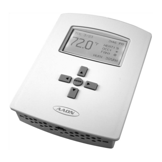
Figure 6 - AAON Mini Controller Startup (See back of the manual for startup form) Home Screen Configuration Space Temperature Setpoint Override... -
Page 14: Main Menu Configuration
Fan Mode (Fan:) When System Enable is set to Auto, the The Fan Mode options available for both the controller will maintain both the space unoccupied occupied modes heating and cooling setpoints with operation operation are Auto and On. depending on the space temperature. When System Enable is set to Heating, the Auto activates the fan only during heating controller will maintain only the space... -
Page 15: Figure 7 - Home Screen With Flashing Service Message
on controllers with a supply air temperature sensor connected. Space CO Alarm Activated when the space CO is above 2000 ppm. Alarm is only available on controllers with CO sensor connected. Date/Time Date/Time menu is used to configure the date and time. Day, month, year and time Figure 7 - Home Screen with Flashing are available for configuration. - Page 16 MIN SETPT DIFF System Minimum setpoint differential between the System menu is used for additional startup cooling and heating space temperature configuration. setpoints. Used for both the occupied and unoccupied modes of operation. Default SYSTEM ENABLE setpoint differential is 2°F and range is 1- System Mode of Operation.
-
Page 17: Advanced Menu Configuration
Advanced Menu Configuration DAMPER - ENTHALPY (Advanced) Application Available economizer options are Enable or Application menu is used for application Disable. configuration. DAMPER - MIN POSITION (%) DEGREE SCALE Minimum economizer damper position. °F or °C Default value is 10% and range is 0-95%. DAMPER - CNTRL (0-100%) Controller application Available options are 0-10 VDC, 10-0 VDC,... - Page 18 FAN - COOL MIN SPEED True activates dehumidification anytime Minimum cooling speed of a variable speed space humidity is outside dehumidification fan. Default is 30%, range is 30-80% and setpoints. Default is False. value must be less than the maximum cooling speed.
-
Page 19: Table 2 - Utc Offset
COMP STG DELAY (MINS) If the controller is used in a BACnet Compressor stage delay. Used for cooling network with UTC synchronization set the and heat pump heating. Default is 3 minutes UTC offset value. The offset value is in and range 2-15 minutes. - Page 20 Factory Restore - Restore option clears all COMP OAT LOW present values, restores configuration to the Compressor cooling outside air temperature defaults and restarts the controller. lockout. Default is 40°F and range is 0-50°F. (Advanced) Inputs OAT HIGH The Inputs menu shows all analog inputs, Description.
- Page 21 HEAT MAX ON Description. Default is 120 units and range is -120-600 units. (Advanced) Security The Security menu allows setting of User, Operator and Administrator access to setpoint adjustment, Main Menu, system mode, occupancy override, operation. Passwords for the User, Operator and Administrator can be changed from this menu.
-
Page 22: Table 3 - Default Access Levels
Default Configuration Access WARNING Default User Password = 0000 Default Operator Password = 1988 QUALIFIED INSTALLER Default Administrator Password = 2425 Improper installation, adjustment, Note: Administrator Password is required to alteration, service or maintenance set security passwords. If changed, keep a cause property damage,... -
Page 23: Controller Configuration Steps
Controller Configuration Steps 3. Main Menu: Advanced: Application: 1. Unit Application Additional Setup: Fan: 2. Heating and Cooling Stages Speeds: Constant 3. Sensors Unocc: On or Auto 4. Supply Fan Occ: On or Auto 5. Features 6. Limits 7. Setpoints 8. -
Page 24: Single Zone Vav Air Conditioner Configuration - Vav Cool + Cv Heat
6. Main Menu: Setpoints: Single Zone Conditioner Configuration - VAV Cool + CV Heat Check Setpoint Values 1. Main Menu: Advanced: Application: App = Standard Opt = # Heat Stages / # Cool Stages 7. Main Menu: Advanced: Date/Time: Check Date and Time 2. -
Page 25: Single Zone Vav Air Conditioner Configuration - Vav Cool + Vav Heat
4. Main Menu: Advanced: Application: 7. Main Menu: Advanced: Date/Time: SAT Control = Cooling Check Date and Time 8. Main Menu: Schedule: 5. Main Menu: Advanced: Limits: Setup a Schedule and Holidays Check Limit Values Single Zone Conditioner 6. Main Menu: Setpoints: Configuration - VAV Cool + VAV Heat Check Setpoint Values 1. - Page 26 2. Main Menu: Advanced: Application: 5. Main Menu: Advanced: Limits: Additional Setup: Sensors: Check Limit Values OAT Sensor = Yes SAT Sensor = Yes 6. Main Menu: Setpoints: Check Setpoint Values 3. Main Menu: Advanced: Application: Additional Setup: Fan: Speeds: Variable Heating and Cooling Unocc: On or Auto Occ: On or Auto Check Minimum Speeds...
-
Page 27: Constant Volume Heat Pump Configuration
8. Main Menu: Schedule: 3. Main Menu: Advanced: Application: Additional Setup: Valve: Setup a Schedule and Holidays Check Reversing Valve Active Mode Constant Volume Heat Pump Configuration 1. Main Menu: Advanced: Application: 4. Main Menu: Advanced: Application: App = Heat Pump Additional Setup: Fan: Opt = # Compressor Stages / with or Speeds: Constant... -
Page 28: Single Zone Vav Heat Pump Configuration- Vav Cool + Cv Heat
6. Main Menu: Advanced: Limits: 9. Main Menu: Schedule: Check Limit Values Setup a Schedule and Holidays 7. Main Menu: Setpoints: Single Zone Heat Pump Check Setpoint Values Configuration- VAV Cool + CV Heat 1. Main Menu: Advanced: Application: App = Standard Opt = # Heat Stages / # Cool Stages 8. - Page 29 3. Main Menu: Advanced: Application: 6. Main Menu: Setpoints: Additional Setup: Fan: Check Setpoint Values Speeds: Variable Cooling Unocc: On or Auto Occ: On or Auto Check Minimum Speed 7. Main Menu: Advanced: Date/Time: Check Date and Time 4. Main Menu: Advanced: Application: SAT Control = Cooling 8.
-
Page 30: Single Zone Vav Heat Pump Configuration- Vav Cool + Vav Heat
Single Zone Heat Pump 4. Main Menu: Advanced: Application: Configuration- VAV Cool + VAV Heat Additional Setup: Fan: 1. Main Menu: Advanced: Application: Speeds: Variable Heating and Cooling App = Heat Pump Unocc: On or Auto Opt = # Compressor Stages / with or Occ: On or Auto without Emergency Heat Check Minimum Speeds... -
Page 31: Modulating Hot Gas Reheat
Setup a Schedule and Holidays 3. Main Menu: Setpoints: Check Humidity Control Setpoint Values Modulating Hot Gas Reheat Mini Controller with space humidity sensor (R80580) and Wattmaster Modulating Hot Gas Reheat Board are required for humidity 4. Setup Supply Air Temperature control. -
Page 32: Economizer
Economizer Override 1. Main Menu: Advanced: Application: 1. Main Menu: Advanced: Application: Additional Setup: Sensors: Additional Setup: Sensors: Configure OA Humidity Sensor if Configure OA Humidity Sensor Enthalpy Controlled 2. Main Menu: Setpoints: 2. Main Menu: Advanced: Application: Check CO Setpoint Value Additional Setup: Damper: Setup Modulating Economizer... - Page 33 Fan Status 1. Main Menu: Advanced: Application: Additional Setup: Sensor: Configure Fan Status Sensor...
-
Page 34: Operation
Heat, Single Zone VAV - VAV Cool + Operation VAV Heat, or Single Zone VAV Heat Pump - VAV Cool + VAV Heat Unit operations should be controlled with the controller, never at the main power RN/RQ - Feature 13 - Special Controls = E, supply, except for servicing, emergency or Y, Z, 2, 3 complete shutdown of the unit. - Page 35 variable capacity scroll compressor is de- Constant Volume Heating Operation - Space activated. Temperature Control When the space temperature has deviated ½ Single Zone VAV Cooling Operation - of the space temperature deadband below Supply Air Temperature Control the heating space temperature setpoint the When the space temperature has deviated ½...
- Page 36 Single Zone VAV Heating Operation - For units with two stage heat pump heating, Supply Air Temperature Control if the variable capacity scroll compressor When the space temperature has deviated ½ operates at a maximum capacity for the of the space temperature deadband below compressor stage delay amount of time and the heating space temperature setpoint the space temperature is still decreasing the...
- Page 37 the emergency heating stages are de- if available, the first stage of emergency activated. heating is activated. Modulating/SCR electric heating operates as If the supply air temperature is decreasing a single stage of auxiliary/emergency below the heating supply air temperature heating.
- Page 38 wired for constant speed/constant volume As the space temperature achieves the operation. heating space temperature setpoint plus ½ of the space temperature the supply fan is de- Single Zone VAV Supply Fan activated (Auto) or operates at the cooling Supply fan operation is selectable between minimum speed (On).
- Page 39 If set to False, Dehumidification Mode will enable only Note: Because of the AAON Mini Controller’s limited number of inputs, when the space heating and cooling setpoints are satisfied (i.e. vent mode if FAN...
-
Page 40: Bacnet Points List
BACnet Points List Table 4 - Analog Values Description Object Read/Write Default Min Space Temp Setpoint Diff 2°F 1°F 15°F Active Cooling Setpoint Active Heating Setpoint Unocc Cooling Setpoint 80°F 55°F 90°F Unocc Heating Setpoint 64°F 55°F 90°F Deadband 2°F 1°F 15°F Occ Min Cooling Setpoint... -
Page 41: Table 5 - Analog Values Continued
Table 5 - Analog Values Continued Cool Supply Fan Max Speed AV44 Setpoint 100% 100% AV45 Dehum Suction PSI Setpoint 119.4 psi 50 psi 250 psi AV46 Dehum Fan Speed Setpoint AV47 Unocc Dehum Setpoint AV48 SAT Low Limit Alarm 40°F 32°F 60°F... -
Page 42: Table 7 - Multi-State Values
Table 7 - Multi-State Values Object Read/Write Description Options MSV1 Application Main Standard, Heat Pump #Heat Stages/#Cool Stages or #Comp Stages/#Emer. MSV2 Application Sub Heat Stages Constant Speed, Variable Speed Cool, Variable MSV3 Fan Control Speed Cool and Heat MSV4 Economizer Damper None, Fully Modulating None, Fan Status, CO... -
Page 43: Maintenance And Support
This includes checking of the airflow, the air filters, condenser water flow and refrigerant charge. Replacement Parts Parts for AAON equipment may be obtained from AAON at www.aaonparts.com. When ordering parts, reference the unit serial number and part number. -
Page 44: Glossary
Glossary BAUD RATE: Default is 38400 and options available include 9600, 19200, 38400 and 76800. CO2 SETPT (PPM): Space CO override setpoint. Default setpoint is 1100 ppm and range is 500-1800 ppm. COMP1 MIN OFF (SECS): Compressor minimum off time. Default is 120 seconds and range is 120-600 seconds. - Page 45 FAN - COOL MAX SPEED: Maximum cooling speed of a variable speed fan. Default is 100%, range is 50-100% and value must be greater than the minimum cooling speed. FAN - COOL MIN SPEED: Minimum cooling speed of a variable speed fan. Default is 30%, range is 30-80% and value must be less than the maximum cooling speed.
- Page 46 MIN SETPT DIFF: Minimum setpoint differential between the cooling and heating space temperature setpoints. Used for both the occupied and unoccupied modes of operation. Default setpoint differential is 2°F and range is 1-15°F. OAT HIGH: Description. Default is 150°F and range is 110-160°F. OAT LOW: Description.
-
Page 47: Aaon Mini Controller Startup Form
AAON Mini Controller Startup Form Date:_______________ Job Name:_____________________________________________________________________ Address:______________________________________________________________________ Model Number:_________________________________________________________________ ______________________________________________________________________________ Serial Number:___________________________________________ Tag:_________________ Startup Contractor:______________________________________________________________ Address:________________________________________________ Phone________________ Pre Startup Checklist Installing contractor should verify the following items: 1. Is there any visible shipping damage? ____________________________ 2. Are the clearances adequate for service and operation? ___________ 3. -
Page 48: Maintenance Log
This log must be kept with the unit. It is the responsibility of the owner and/or maintenance/service contractor to document any service, repair or adjustments. AAON Service and Warranty Departments are available to advise and provide phone help for proper operation and replacement parts. -
Page 49: Literature Change History
Literature Change History October 2010 Revision of the manual correcting the sequence of operation for enthalpy controlled economizer. December 2013 Added BACnet Points List, glossary, and how relay output 5 can be used as the Y1 compressor 1 relay output. March 2014 Added dehumidification priority. -
Page 52: R98200 · Rev. B
User’s Manual R98200 · Rev. B · 140311 It is the intent of AAON to provide accurate and current product information. However, in the interest of product improvement, AAON reserves the right to change pricing, specifications, and/or design of its product without notice, obligation, or liability.
Need help?
Do you have a question about the Mini Controller and is the answer not in the manual?
Questions and answers