Table of Contents
Advertisement
Quick Links
Advertisement
Table of Contents

Subscribe to Our Youtube Channel
Related Manuals for Gefen TOOLBOX


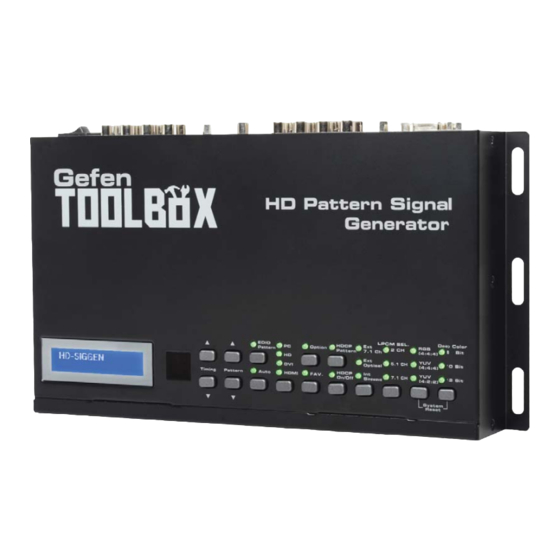
Summary of Contents for Gefen TOOLBOX
- Page 1 Gefen HD Pattern Signal Generator GTB-HD-SIGGEN User Manual www.gefentoolbox.com...
- Page 2 Chatsworth, CA 91311 www.gefentoolbox.com support@gefentoolbox.com Notice Gefen, LLC reserves the right to make changes in the hard ware, packaging and any accompanying doc u men ta tion without prior written notice. HDMI, the logo, and High-Defi nition Multimedia Interface are trademarks or registered trademarks of HDMI Licensing in the United States and other countries.
-
Page 3: Table Of Contents
CONTENTS Introduction Operation Notes Features Top Panel Layout Top Panel Descriptions Back Panel Layout Back Panel Descriptions Control Panel Layout Control Panel Descriptions 11 Connecting The GefenToolBox HD Pattern Signal Generator Wiring Diagram 12 Operating The GefenToolBox HD Pattern Signal Generator Display Window Timing Buttons Pattern Buttons... - Page 4 CONTENTS Unique Patterns ColorSetting Pattern Motion Pattern Favorite Timing Favorite Pattern EDID Read / Write Translating EDID (Verbose Form) Generating the EDID Checksum Saving an EDID to a File Clearing the EDID from Memory Loading an EDID from a File Comparing EDID Data Writing EDID to a Sink Erasing the EDID of a Sink...
-
Page 5: Introduction
/ pattern. This device can be conveniently controlled via the front panel buttons, the IR remote or the downloadable soft- ware from the Gefen Web site. In addition to its portability, this signal generator is wall-mountable and fi eld-upgradeable. -
Page 6: Operation Notes
OPERATION NOTES READ THESE NOTES BEFORE INSTALLING OR OPERATING THE GEFENTOOLBOX HD PATTERN SIGNAL GENERATOR • The GefenToolBox HD Pattern Signal Generator can be controlled using a software application and RS-232. Download this application from the Gefen Web site at: http://www.gefen.com/kvm/support/download.jsp... -
Page 7: Features
Supports NTSC and PAL frame rates • 2 CH, 5.1 CH, and 7.1 CH LPCM internal sine wave generator • RS-232 control via the downloadable software from the Gefen Web site. • Small form factor; easy to transport • Supports HD timings for VGA output •... -
Page 8: Top Panel Layout
TOP PANEL LAYOUT Top Panel... -
Page 9: Top Panel Descriptions
TOP PANEL DESCRIPTIONS Top Panel LCD Display Displays pattern and timing information in addition to other functions used by the Signal Generator. IR Window Receives signals from the IR Remote Control unit. Control Panel See page 8 for a detailed view of the Control Panel. -
Page 10: Back Panel Layout
BACK PANEL LAYOUT Back Panel... -
Page 11: Back Panel Descriptions
BACK PANEL DESCRIPTIONS Back Panel Overscan Button By default, the GefenToolBox HD Pattern Signal Generator is set to underscan mode. If the video signal does not fi ll the entire display, press this button once to switch to overscan mode. Press the Overscan button a second time to return to underscan mode. -
Page 12: Control Panel Layout
CONTROL PANEL LAYOUT Control Panel... -
Page 13: Control Panel Descriptions
CONTROL PANEL DESCRIPTIONS Control Panel Timing (Down) Cycles backward through the list of timings. Timing (Up) Cycles forward through the list of timings. Pattern (Down) Cycles backward through the list of patterns. Pattern (Up) Cycles forward through the list of patterns. Auto Indicator This LED will glow bright green when the Signal Generator is placed in Auto mode. - Page 14 CONTROL PANEL DESCRIPTIONS 14 Option Indicator This LED will glow bright green when the Signal Generator is in Option mode. 15 HDCP On / Off Indicator This LED will glow bright green when HDCP content is being sent from the Signal Generator.
-
Page 15: Connecting The Gefentoolbox Hd Pattern Signal Generator
Turn on the HDTV display fi rst, then turn on the HD Pattern Signal Generator. Wiring Diagram for the GefenToolbox HD Pattern Signal Generator HDMI CABLE Gefen VGA CABLE HDMI CABLE RS-232 CABLE DIGITAL AUDIO TOSLINK CABLE STEREO L /R AUDIO CABLE... -
Page 16: Operating The Gefentoolbox Hd Pattern Signal Generator
OPERATING THE HD PATTERN SIGNAL GENERATOR Display Window The Display Window of the GefenToolBox HD Pattern Signal Generator is a 16-character, 2-line display. This display will show the currently selected timing and pattern on the output. In addition, this display is also used for providing information or messages about the connected devices. -
Page 17: Pattern Buttons
OPERATING THE HD PATTERN SIGNAL GENERATOR Pattern Buttons To change the pattern, use the ▲ and ▼ Pattern buttons. The ▲ button will move forward through the patterns (see the pages 14 - 35 for a list of available patterns). Use the ▼ button to move backward through the patterns. Cycles forward through the timings ... -
Page 18: Pattern Summary
PATTERN SUMMARY Purity Pattern 01 - Pattern 08 (P01 - P08) Press the [OPTION] button to switch between Full Screen and Windowed format. White Blue Magenta Green Cyan Yellow Black Red (P03) and Green (P05) are often used to check color purity. When using the Red pattern, no other color should be present on the screen. -
Page 19: Color Settings
PATTERN SUMMARY Green (P05) provides a color purity check for display devices that use three in-line guns. The in-line confi guration defi nes guns which are positioned horizontally with the green gun located in the center (R-G-B). Blue (P02) is a complementary color. This pattern is frequently used to test color performance. - Page 20 PATTERN SUMMARY Switch between full and limited color range When using Pattern 09 - Pattern 12, a black screen will be displayed, fi rst. Use the [OPTION] to enable to the pattern.
-
Page 21: Color Bars
PATTERN SUMMARY Color Bars Pattern 14 - Pattern 17 (P14 - P17) There are four different color bar patterns. Use the [OPTION] button on Pattern 14 (P14) and Pattern 16 (P16) to switch between 75 IRE (Option LED indicator OFF) and 100 IRE (Option LED indicator ON). -
Page 22: Black White Line
PATTERN SUMMARY Black White Line Pattern 23 -Pattern 26 (P23 - P26) The vertical pattern serves as a test for the horizontal bandwidth and phase behavior of a color monitor. This pattern can also be used to verify the video amplifi er and color temperature. -
Page 23: Pluge
PATTERN SUMMARY Pluge Pattern 27 - Pattern 31 (P27 - P31) Pluge (Picture line up) patterns are used to perform accurate and consistent line-up of the output signal (video). The concept behind Pluge patterns is to adjust the brightness control so that the fi rst bar is invisible, while the second bar remains visible. -
Page 24: Grid
PATTERN SUMMARY Grid Pattern 32 - Pattern 33 (P32 - P33) Grid and cross patch patterns are mainly used for detecting corner convergence (“pin cushions”). GRID Cross Hatch Press the [OPTION] button on Pattern 33 (P33) to toggle between the black/white (Option LED indicator is OFF) and white/black (Option LED indicator is ON) cross hatch patterns. -
Page 25: Circles
PATTERN SUMMARY Circles Pattern 37 (P37) Produces a pattern with large circles on the screen. This pattern is primarily used for checking the overall geometry and linearity of the display. CIRCLES EDID Pattern 38 (P38) Displays the EDID pattern screen. This pattern is used to analyze the EDID data of the connected sink (display, A/V receiver, etc). - Page 26 PATTERN SUMMARY When the EDID pattern is selected, the display will appear as follows: To use the EDID pattern, follow the instructions below: Press the [OPTION] button. The EDID Analysis Menu will be displayed. The fi rst line of the menu will be highlighted in blue.
- Page 27 PATTERN SUMMARY • HDMI / DVI Out Reads the EDID of the sink (display, A/V receiver, etc) connected to the HD Pattern Signal Generator. • HDMI / DVI In Reads the built-in EDID of the HD Pattern Signal Generator. • VGA PC / HD Out Reads the EDID of the display connected to the VGA port of the HD Pattern Signal Generator.
- Page 28 PATTERN SUMMARY The HD Pattern Signal Generator will display the Vendor / Product Id EDID information on the screen. Your Vendor / Product Id EDID information will most likely differ from the example below: In this example, the HD Pattern Signal Generator reported the following EDID information for the Vendor / Product Id in Block 0: EDID OUT Analysis Block0 Page 2 Manufacturer Name.
-
Page 29: Audio
PATTERN SUMMARY Audio Pattern 39 (P39) This pattern displays the audio information of the connected source device, such as the number of audio channels, sampling rate, and I S (Intergrated Interchip Sound) bus data. AUDIO The table below provides a listing of the audio input and audio output combinations when using the Audio Pattern (P39). - Page 30 PATTERN SUMMARY In the example above, the Audio Pattern is shown using the external 7.1 channel audio input. The Audio Input Selection button is used to change the audio input type. Audio Input Selection button Text that is highlighted in yellow indicates that the value may be changed. In the illustration above, the HDMI output can be toggled between 2 channel LPCM and 6 channel (5.1) channel LPCM audio using the Audio Channel selection button.
- Page 31 PATTERN SUMMARY External Optical Audio Input Changing the audio input to EXT OPTICAL, using the Audio Input Selection button will produce the following screen: In the example above, since no optical input was used, the Source Format Detection displays None. The External Optical Audio Input does not support bitstream decoding.
- Page 32 PATTERN SUMMARY Changes the Sampling Rate Selects the serial Audio channel data line selection button The I S data line option is only present when the HD Pattern Signal Generator is set to 5.1 CH or 7.1 CH audio. In 2 CH mode, the I S bus can only be enabled or disabled (muted).
-
Page 33: Hdcp
PATTERN SUMMARY HDCP Pattern 40 (P40) This pattern displays HDCP information such as handshaking and link integrity test. If the sink (output device) is a repeater, both the B and B are displayed. KSv’ HDCP When the HDCP pattern is selected, the display will appear as follows: The HDCP pattern (P40) can also be discreetly accessed by pressing the [HDCP] button on the top panel. - Page 34 PATTERN SUMMARY Once HDCP has been enabled, the screen will appear similar to the following: The HDCP pattern provides a full three phase authentication: Phase 1: The HD Pattern Signal Generator writes a 64-bit random number (A ) to the sink / receiver (Rx).
-
Page 35: Motion
PATTERN SUMMARY In the example above, the HDCP authentication process is successful. Note that the sink (Rx) was not identifi ed as a repeater. For a display, this is normal. A repeater is defi ned as an active device which has one or more HDMI inputs and one or more HDMI outputs that work with HDCP. - Page 36 PATTERN SUMMARY When a valid video input signal is detected, the In Timing pattern will display information similar to the following: Press the [OPTION] button to perform a hot-plug (HPD) event. Triggering an HPD event is the similar to disconnecting and reconnecting the input source. In Video The In Video pattern provides information about color space, color depth, extended colorimetry (if applicable), HDCP, and AVI infoframe information.
- Page 37 PATTERN SUMMARY As with the In Timing pattern (P42), if a valid signal is not detected on the input, the top line will display No Signal. No input signal detected Press the [OPTION] button to trigger an HPD event. In Audio The In Audio pattern provides audio information, including sampling rate, bit depth, audio encoding, and the number of audio channels.
-
Page 38: System Setup
PATTERN SUMMARY System Setup Pattern 45 (P45) Built-in Rx EDID setup, IR remote address setup. System Setup When the System Setup pattern is selected, the display will appear as follows: Press [OPTION] to do system setup Press the [OPTION] button to bring up the following screen: System Setup ►Copy OUT EDID to IN EDID... - Page 39 PATTERN SUMMARY There are four options under the System Setup pattern. Use the ▲ or ▼ buttons to select the desired option. Press the [OPTION] button to accept the selection. Copy OUT EDID to IN EDID Copies the EDID from the device/display connected to the HD Pattern Signal Generator and stores it in a local buffer on the unit.
-
Page 40: Timing Summary
TIMING SUMMARY The following table lists the available graphic and video timings used by the HD Pattern Signal Generator. Timing Number Timing 640 x 480 @ 60 Hz 640 x 480 @ 72 Hz 640 x 480 @ 75 Hz 640 x 480 @ 85 Hz 800 x 600 @ 56 Hz 800 x 600 @ 60 Hz... - Page 41 TIMING SUMMARY Timing Number Timing 720 x 576i @ 50 Hz 720 x 576p @ 50 Hz 1280 x 720p @ 50 Hz 1920 x 1080i @ 50 Hz 1920 x 1080p @ 50 Hz 1920 x 1080p @ 23 Hz 1920 x 1080p @ 24 Hz 1366 x 768 @ 60 Hz 1366 x 768 @ 50 Hz...
-
Page 42: Hd Pattern Signal Generator Software
The HD Pattern Signal Generator can be controlled via RS-232 on a PC running Windows®, using the HD-SIGGEN software. The program is available for down- load on the Gefen Web site: http://www.gefen.com/kvm/support/download.jsp Installing the Software Unzip the archive fi le, containing setup.exe, SETUP.LST, and version.txt. - Page 43 HD PATTERN SIGNAL GENERATOR SOFTWARE The installer will begin by copying the required installation fi les, to the hard drive: After the required fi les have been copied to the hard drive, the installer Wel- come screen will appear: Click the OK button to continue with the installation. Click the Exit Setup button to exit the installer.
- Page 44 HD PATTERN SIGNAL GENERATOR SOFTWARE The destination directory can be changed. The default installation directory for Windows 7® is C:\Program Files(x86)\HD-SIGGEN. For other ver- sions of the Windows® operating system, the default installation location will be C:\Program Files\HD-SIGGEN. Click to install to the default directory Click to change the default directory...
-
Page 45: Connecting The Rs-232 Cable
HD PATTERN SIGNAL GENERATOR SOFTWARE After the installer has successfully completed the installation process, the following message box will be displayed: Click the OK button to dismiss the message box and exit the installer. Connecting the RS-232 cable Before launching the HD Pattern Signal Generator software, an RS-232 cable must be connected from the back of the HD Pattern Signal Generator to the computer which has the HD Pattern Signal Generator software installed. -
Page 46: Running The Hd Pattern Signal Generator Software
HD PATTERN SIGNAL GENERATOR SOFTWARE Running the HD Pattern Signal Generator Software Launch the HD Pattern Signal Generator Software by clicking on the application icon in the Windows® Start Menu: The example below, shows the HD-SIGGEN application icon as it appears in the Windows 7®... - Page 47 HD PATTERN SIGNAL GENERATOR SOFTWARE After the HD Pattern Signal Generator is launched, the following screen will be displayed: Select the COM port from the pull-down list. COM port 1 is selected by default. Click the Connect button to initialize the connection between the software and the HD Pattern Signal Generator.
-
Page 48: Selecting The Timing
HD PATTERN SIGNAL GENERATOR SOFTWARE Selecting the Timing Use the Timing Select button to select the timing / resolution of the output signal. Press the SET button to set the timing. Select the timing in the Timings window Retrieves the current Click the SET button settings to enable the timing... -
Page 49: Selecting The Pattern
HD PATTERN SIGNAL GENERATOR SOFTWARE Selecting the Pattern Use the Pattern Select button to select the desired pattern. Press the SET button to enable the pattern. Select the pattern in the Patterns window Click the SET button A “Link Error” message caused to enable the pattern by the Refresh button not being pressed after connecting to the... -
Page 50: Unique Patterns
HD PATTERN SIGNAL GENERATOR SOFTWARE Unique Patterns Pattern 13 (ColorSetting) and Pattern 41 (Motion) can be selected from the top panel buttons on the HD Pattern Signal Generator. However, they provide addi- tion parameters which can only be modifi ed using the HD-SIGGEN software. Color Setting Select the ColorSetting pattern (P13). - Page 51 HD PATTERN SIGNAL GENERATOR SOFTWARE Adjust the Red, Green, Blue, and Grey sliders to render the desired color. Press the SET button to upload the current settings to the ColorSetting pattern. Use the sliders to Click the SET button adjust the color to upload the new color settings...
-
Page 52: Motion Pattern
HD PATTERN SIGNAL GENERATOR SOFTWARE Unique Patterns Pattern 13 (ColorSetting) and Pattern 41 (Motion) can be selected from the top panel buttons on the HD Pattern Signal Generator. However, they provide addi- tion parameters which can only be modifi ed using the HD-SIGGEN software. Motion Select the Motion pattern (P41). - Page 53 HD PATTERN SIGNAL GENERATOR SOFTWARE A custom string, up to 12 characters in length, can be entered in the Custom String fi eld. Click the Upload button to update the HD Pattern Signal Generator with the new pattern. Use the sliders to A custom adjust the color message can be...
-
Page 54: Favorite Timing
HD PATTERN SIGNAL GENERATOR SOFTWARE Favorite Timing A list of favorite timings can be assembled and stored in the HD Pattern Sig- nal Generator. The [FAV] button, on the front panel, can then be used to cycle through the list of timings that is created. In the Timings window, place a check mark in the boxes of the timings to be added to the Favorites list. -
Page 55: Favorite Pattern
HD PATTERN SIGNAL GENERATOR SOFTWARE Favorite Pattern A list of favorite patterns can be assembled and stored in the HD Pattern Signal Generator. The [FAV] button, on the front panel, can then be used to cycle through the pattern list that is created. In the Patterns window, place a check mark in the boxes, next to the timings to be added to the Favorites list. -
Page 56: Edid Read / Write
HD PATTERN SIGNAL GENERATOR SOFTWARE EDID Read / Write The HD Pattern Signal Generator has the ability to read EDID data. EDID data can also be saved, loaded, written, erased, compared, interpreted, and summed. Each of these features will be covered in this section. Clicking the EDID Read / Write button will display the following screen: Reading EDID Select the Source by clicking one of the three radio buttons at the top portion... - Page 57 HD PATTERN SIGNAL GENERATOR SOFTWARE In this example, the EDID is being read from the display connected to the HD Pattern Signal Generator. Click the READ button on the READ Panel. READ button WRITE Panel READ Panel The READ and COMP (compare) functions are only available under the READ panel.
- Page 58 HD PATTERN SIGNAL GENERATOR SOFTWARE If the EDID is read successfully, the EDID will appear in the READ Panel: Translating the EDID After the EDID has been read, it can be translated into verbose form by clicking the TRANS (Translate) button in the READ panel: Click the TRANS button to display the EDID in verbose form...
- Page 59 HD PATTERN SIGNAL GENERATOR SOFTWARE The Translate [Read] EDID screen: Clicking on the one of the items in the panel on the left, will display the information in the panel on the right. Some items will have a [+] symbol next to them, indicating that additional information is available for that section:...
- Page 60 HD PATTERN SIGNAL GENERATOR SOFTWARE Click the [+] button to expand any section where additional information is present. In the example below, the [+] button has changed to a [-] symbol after the Standard Timings section has been expanded: The information about the Standard Timing 1, Standard Timing 2, and Standard Timing 3 is listed in the panel on the right.
- Page 61 HD PATTERN SIGNAL GENERATOR SOFTWARE The EDID Report window is shown below. Click the Save button to save the fi le in .TXT format. Click the Exit button to return to the Translate EDID screen.
-
Page 62: Generating The Edid Checksum
HD PATTERN SIGNAL GENERATOR SOFTWARE Generating the EDID Checksum Once an EDID has been read or loaded into the HD Pattern Signal Generator, a checksum can be generated. Read or load an EDID fi le into the HD Pattern Signal Generator. Click the SUM button under the READ panel. - Page 63 HD PATTERN SIGNAL GENERATOR SOFTWARE The EDID Checksum dialog will be displayed. Select the method of how unused bytes will be calculated into the checksum by clicking either the 0x00 or 0xFF radio button. Select how unused bytes will be used in calculating the checksum Adjust the EEPROM size, if necessary, by selecting it from the EEPROM Size drop-down list: 256, 512, 1024, or 2048 bytes.
- Page 64 HD PATTERN SIGNAL GENERATOR SOFTWARE Click the CHECKSUM button to generate the EDID checksum. By default, the checksum will be restricted to the lower 4 digits. This feature can be disabled unchecking the Show lower 4 digits of checksum only box. Uncheck to disable truncation of checksum In the example above, if the checksum were calculated by disabling the...
-
Page 65: Saving An Edid To A File
HD PATTERN SIGNAL GENERATOR SOFTWARE Saving an EDID to a File Any EDID can be saved to a fi le, once it has been read into the HD Pattern Signal Generator. Once an EDID has been read, click the SAVE button. Click the SAVE button to save the EDID to a fi... - Page 66 HD PATTERN SIGNAL GENERATOR SOFTWARE The Save EDID fi le dialog box will be displayed: Select a name for the EDID fi le and type it in the File name box. The fi le can be saved as either a .hex fi le or a .bin fi le. Select the fi...
- Page 67 HD PATTERN SIGNAL GENERATOR SOFTWARE Select the directory where the EDID fi le will be saved and click the Save but- ton on the dialog box. By default, the EDID fi le will be saved in the working directory of the HD Pattern Signal Generator software directory.
-
Page 68: Clearing The Edid From Memory
HD PATTERN SIGNAL GENERATOR SOFTWARE Clearing the EDID from Memory Click the Clear button to clear the EDID from memory. Clears the EDID from memory If an EDID is loaded (OPEN) under the WRITE panel, use the CLEAR button to clear it from memory. -
Page 69: Loading An Edid From A File
HD PATTERN SIGNAL GENERATOR SOFTWARE Loading an EDID from a File An EDID fi le in binary (.bin) format or in text format (.hex) can be loaded into the HD Pattern Signal Generator. Click the OPEN button under the WRITE panel. If necessary, refer to page 61 on how to save an EDID to a fi... - Page 70 HD PATTERN SIGNAL GENERATOR SOFTWARE The EDID fi le will be loaded into the HD Pattern Signal Generator and dis- played in the WRITE panel. In the example below, an EDID has been read using the HD Pattern Sig- nal Generator software (using the READ function) and an EDID has been loaded from a fi...
-
Page 71: Comparing Edid Data
HD PATTERN SIGNAL GENERATOR SOFTWARE Comparing EDID Data The HD Pattern Signal Generator software can compare two EDID data structures. One EDID is read from a sink (display, A/V receiver, etc) and the other is loaded into the HD Pattern Signal Generator software using the OPEN function. - Page 72 HD PATTERN SIGNAL GENERATOR SOFTWARE If the two EDID data structures are identical, then a message will be displayed indicating that the compare process has passed: Click the OK button to return to the EDID Read / Write screen. If there are differences in the two EDID data structures, then the compare pro- cess will fail.
-
Page 73: Writing Edid To A Sink
HD PATTERN SIGNAL GENERATOR SOFTWARE Writing EDID to a Sink After an EDID has been read from another source or loaded from a fi le, the EDID can be written to the sink connected to the output of the HD Pattern Signal Generator. -
Page 74: Erasing The Edid Of A Sink
HD PATTERN SIGNAL GENERATOR SOFTWARE Erasing the EDID from a Sink The ERASE function will erase the EDID of a sink device. Be sure to save a copy of the sink’s EDID before performing the ERASE function. This will allow the sink’s EDID to be restored if necessary. -
Page 75: Opening Recent Edid Files
HD PATTERN SIGNAL GENERATOR SOFTWARE Opening Recent EDID Files The HD Pattern Signal Generator software keeps a record of the last ten fi les which were opened or saved. To access the most recently used fi les, do the following: Click the Pre-F button in the WRITE panel. -
Page 76: Autorun Confi Guration
HD PATTERN SIGNAL GENERATOR SOFTWARE Autorun Confi guration The Autorun Confi guration option allows custom programming of timings and patterns used by the Autorun Demonstration mode (pressing the AUTO button on the front panel): Click the Autorun Confi g button. If necessary, you can press the Download button to read the current Autorun settings from the HD Pattern Signal Generator. -
Page 77: Panel Control
HD PATTERN SIGNAL GENERATOR SOFTWARE An existing timing and pattern set can be replaced by clicking (highlighting) the set, selecting the new timing and new pattern from the drop-down list boxes, then pressing the Add / Replace button. Use the Delete button to remove a timing / pattern set from the Autorun Confi... -
Page 78: Getting The Hardware And Firmware Version
HD PATTERN SIGNAL GENERATOR SOFTWARE Getting the Hardware and Firmware Version Press About button on the top portion of the HD Pattern Signal Generator software. Press to display hardware and software information The About screen will be displayed, showing the software and fi rmware versions: Press the OK button to dismiss the About box and return to the HD Pattern Signal Generator software window. -
Page 79: Wall Mounting Instructions
WALL MOUNTING INSTRUCTIONS The GefenToolBox HD Pattern Signal Generator should be mounted vertically in a wall or cabinet with wood/drywall screws as shown in the diagram above. There should be an inch or two of clearance between the edges of the unit and any walls or vertical surfaces to allow for enough clearance for insertion and removal of cables on the back of the unit. -
Page 80: Glossary
GLOSSARY Apple Display Connector. The ADC interface is a proprietary interface developed by Apple that combines analog and digital signals, USB, and power in a single cable. CAT-5 Category-5 cable, commonly known as Cat-5, is an unshielded twisted pair type cable designed for high signal integrity. -
Page 81: Specifi Cations
GLOSSARY DDWG An acronym for Digital Display Working Group. DDWG are the creators of the DVI specifi cation. Dolby Digital® This is a digital surround sound technology used in movie theaters and upscale home theater systems that enhances audio. Home theater components with this technology work in conjunction with a “8.1-speaker”... - Page 82 GLOSSARY HDCP High-Bandwidth Digital Content Protection. Created by Intel, HDCP is used with HDTV signals over DVI and HDMI connections and on D-Theater D-VHS recordings to prevent unauthorized duplication of copy written material. HDMI The High-Defi nition Multimedia Interface (HDMI) is an industry-supported, uncompressed, all-digital audio/video interface.
- Page 83 GLOSSARY IEEE 1394a A type of cabling technology for transferring data to and from digital devices at high speed. Some professional digital cameras and memory card readers connect to the computer over FireWire. FireWire card readers are typically faster than those that connect via USB. Also known as IEEE 1394, FireWire was invented by Apple Computer but is now commonly used with Windows-based PCs as well.
- Page 84 GLOSSARY NTSC NTSC is an acronym for National Television Systems Committee. NTSC is the current analog television standard used in North America, most of South America, Burma, South Korea, Taiwan, Japan, and the Philippines. An acronym for Phase Alternate Line. PAL is the analog television display standard that is used in Europe and certain other parts of the world.
- Page 85 GLOSSARY SDI is the acronym for Serial Digital Interface. SDI is used for standard defi nition applications (SMPTE 259M) with bit rates of 270 Mb/s, 360 Mb/s, 143 Mb/s, and 177 Mb/s. 270 Mb/s is the most common. Bit rates below 270 Mb/s were designed for the digital transmission of composite (NTSC or PAL) video.
- Page 86 GLOSSARY USB is an acronym for Universal Serial Bus. USB can connect computer peripherals such as mice, keyboards, digital cameras, printers, personal media players, fl ash drives, Network Adapters, and external hard drives. For the most part, USB has made interfaces such as serial and parallel ports obsolete. VESA VESA (Video Electronics Standards Association) is an international standards entity for computer graphics.
-
Page 87: Specifications
SPECIFICATIONS Maximum Pixel Clock................165 MHz Input Video Signal ................1.2 volts p-p Input DDC Signal ................. 5 volts p-p (TTL) Video Input............(1) HDMI Type A ,19-pin, female Video Output............(1) HDMI, Type A, 19-pin, female Video Output.................(1) HD15, female Analog Audio Inputs...... -
Page 88: Warranty
Gefen warrants the equipment it manufactures to be free from defects in material and workmanship. If equipment fails because of such defects and Gefen is notifi ed within two (2) years from the date of shipment, Gefen will, at its option, repair or replace the equipment, provided that the equipment has not been subjected to mechanical, electrical, or other abuse or modifi... - Page 90 Rev A4 20600 Nordhoff St., Chatsworth CA 91311 1-800-545-6900 818-772-9100 fax: 818-772-9120 www.gefentoolbox.com support@gefentoolbox.com This product uses UL listed power supplies.
Need help?
Do you have a question about the TOOLBOX and is the answer not in the manual?
Questions and answers