Table of Contents
Advertisement
_____________________________________________________________________________________________________________________________________
DIGITAL MULTIMETER 5017
7 ½ Digit Precision Multimeter with IEEE-488 and RS232 Interface
DMM 5017 / DMM 5017 SC
User´s Manual
PREMA Semiconductor GmbH
Robert-Bosch-Str. 6
•
D-55129 Mainz • Germany
Tel. +49-6131-5062-20
Fax. +49-6131-5062-22
•
E-Mail: instruments @ prema.com
AS5017-0045
Internet: http: / / www.prema.com
Subject to change without notice
Advertisement
Table of Contents

Summary of Contents for Prema DMM 5017
-
Page 1: Digital Multimeter
_____________________________________________________________________________________________________________________________________ DIGITAL MULTIMETER 5017 7 ½ Digit Precision Multimeter with IEEE-488 and RS232 Interface DMM 5017 / DMM 5017 SC User´s Manual PREMA Semiconductor GmbH Robert-Bosch-Str. 6 • D-55129 Mainz • Germany Tel. +49-6131-5062-20 Fax. +49-6131-5062-22 • E-Mail: instruments @ prema.com AS5017-0045 Internet: http: / / www.prema.com... -
Page 2: Table Of Contents
Table of Contents _____________________________________________________________________________________________________________________________________ Table of Contents TABLE OF CONTENTS 1 INTRODUCTION 1.1 Features 1.2 Various Versions 1.3 Important Safety Instructions Reading the User Manual Further Safety Instructions Predictability of Dangers Proprietary Rights Conformity Declaration Proper Utilization as intended Availability of the User Manual 2 GETTING STARTED 2.1 Delivery 2.2 Safety Guidelines... - Page 3 Table of Contents _____________________________________________________________________________________________________________________________________ 3.5 Measuring Resistance 3.6 Measuring Temperature 3.7 Frequency and Period Measurement 3.8 Continuity Test 3.9 Selecting Measurement Ranges 3.10 Setting the Integration Time / Resolution 3.11 Display Display with Settings Meaning of the Settings Display with Mathematics 3-10 Display with Channel 3-10...
- Page 4 Table of Contents _____________________________________________________________________________________________________________________________________ Preselecting the Command Set for Remote Control 4-19 Selecting the Temperature Sensor 4-20 Activating the Loudspeaker 4-21 Setting the Display Formats 4-21 Setting the Scanner Mode 4-23 4.12 Error Messages 4-24 5 REMOTE CONTROL 5.1 Configuration Select Interface Configuring the RS232 Interface Configuring the IEEE-488 Interface...
- Page 5 5-25 Difference between 5017 and 6001 concerning hardware 5-27 6 CALIBRATION 6.1 Calibration Periods 6.2 PREMA Calibration Service 6.3 Necessary Equipment 6.4 Automated Calibration 6.5 Important Steps prior to Calibration 6.6 PIN Number and Calibration Switch Changing the PIN Number 6.7 Offset Correction...
- Page 6 Table of Contents _____________________________________________________________________________________________________________________________________ Reference 8.3 Measurement of AC Voltage Frequency, Period RMS to DC Converter 8.4 Application of Microprocessors Main Processor Power Management Other processors 8.5 Ports Display Memory Serial Port IEEE-488 Port Trigger Port 8.6 Measurement Inputs Front / Rear Measurement Connectors 8.7 Power 8.8 5017SC 8-10...
- Page 7 Table of Contents _____________________________________________________________________________________________________________________________________ 10.3 Pt100 Temperature Probes (3011 and 3012) 10-2 10.4 Test Lead Set (3014) 10-2 10.5 Set of Short Circuit Plugs (3016) 10-3 10.6 Current Shunt (3017) 10-3 10.7 RS232 Cable (3018) 10-3 10.8 Carrying Case (4100) 10-3 10.9 Accessories for the IEEE488 Bus 10-3...
-
Page 8: Introduction
_____________________________________________________________________________________________________________________________________ 1 Introduction With the Digital Multimeter 5017 you are now the owner of a 7 ½ digit measuring instrument of the newest generation from PREMA. This instrument is convincing by virtue of its outstanding measuring capabilities and functional versatility. -
Page 9: Important Safety Instructions
Proper working procedure with this instrument is possible only after reading all in- structions, hints and procedure specifications attentively and understanding them. Please get in touch with PREMA before commencing operation of the instrument if you do not understand something in the user manual or the instructions, procedural descriptions and safety regulations are unclear. -
Page 10: Predictability Of Dangers
This user manual is protected by proprietary rights. No part thereof may be copied, reproduced or distributed in any form without prior written permission. Conformity Declaration PREMA has issued an EC conformity declaration for this instrument. This declaration certifies that the instrument complies with the relevant requirements of the EC direc- tives. -
Page 11: Availability Of The User Manual
All warning and safety instructions attached to the instrument must be held complete and in clearly readable condition. No modifications, attachments or conversions of the instruments are permitted with- out consent and approval by PREMA, otherwise the conformity becomes void. -
Page 12: Getting Started
_____________________________________________________________________________________________________________________________________ 2 Getting Started 2.1 Delivery Every PREMA unit is thoroughly and carefully checked before it is shipped, to ensure that it is in flawless condition, and that its technical characteristics are within specifi- cations. Consequently, upon receipt, the unit should be in perfect condition, mechanically and electrically. -
Page 13: Safety Guidelines
The multimeter may only be utilized for the measurement functions that are described in the Technical Specifications. It is especially important to adhere to the load limits of the input connectors. PREMA accepts no responsibility for any damage arising from improper operation. -
Page 14: Safety Symbols
2.5 Connecting the Unit to Main Power This PREMA measurement unit is designed to be connected to AC Main Voltage, at a frequency of 50 Hz or 60 Hz. The rear panel of the unit is equipped with a standard... -
Page 15: Grounding
Grounding _____________________________________________________________________________________________________________________________________ Before connecting the unit to power, you should make sure that it is set to the right voltage (indicator and fuse). The voltage selection switch with integrated fuse is located right under the power connector, where you can also read off the current voltage setting; a setting of "220V"... -
Page 16: Warranty
2 Getting Started _____________________________________________________________________________________________________________________________________ 2.7 Warranty PREMA warrants the reliable function of the unit for a period of two years from the date of delivery. Repairs that need to be carried out during the warranty period are not billed to you. -
Page 17: Connection Of Measurement Leads
Connection of Measurement Leads _____________________________________________________________________________________________________________________________________ 2.10 Connection of Measurement Leads The measurement inputs are implemented as safety connectors. PREMA strongly rec- ommends the use of safety banana plugs with contact protection (see Appendix A, “Accessories, Safety Lead Set”). V-Hi Connector... - Page 18 2 Getting Started _____________________________________________________________________________________________________________________________________ The following table gives information about the connection of measurement cables: Measurement Hi Connector Lo Connector DC and AC Voltage V-Hi Connector V-Lo Connector DC and AC Current Amps-Hi Connec- V-Lo Connector 2-wire Resistance V-Hi Connector V-Lo Connector 4-wire Resistance Source...
-
Page 19: Operation With Rear Panel Inputs And Scanner
Rack Mounting _____________________________________________________________________________________________________________________________________ Operation with rear panel inputs and Scanner If the 5017 is to be operated from the rear panel inputs or the built-in scanner, please proceed as follows: 1. Please remove all measurement cables from the connectors and unplug the unit. -
Page 20: Miscellaneous
In our opinion, the manual re-positioning of the Front-Rear cable-set connector is not the most elegant, but certainly the safest solution at the moment. This does not mean, however, that PREMA will not come up with a completely new solution in the future. Scanner with Model 5017SC For the model 5017SC with integrated scanner it is important to take the DC and AC voltage limits of the Scanner into account, depending on which option is installed. - Page 21 Miscellaneous _____________________________________________________________________________________________________________________________________ 2-10...
-
Page 22: Quick Start
3 Quick Start _____________________________________________________________________________________________________________________________________ 3 Quick Start 3.1 Default Settings When the unit is turned on for the first time, the following settings are defaulted to: Measurement Function Vdc • Measurement Range 300V • Measurement Time 1s • Front Input Connectors Active •... -
Page 23: Measuring Voltage
Measuring Voltage _____________________________________________________________________________________________________________________________________ 3.3 Measuring Voltage Measurement Functions DC Voltage AC Voltage AC Voltage with DC Component key and COUPL Measurement Ranges 300mV, 3V, 30V, 300V, 1000V 200mV, 2V, 20V, 200V, 700V Resolution and Measurement Times 20 / 40 / 100 ms 5½... -
Page 24: Measuring Current
3 Quick Start _____________________________________________________________________________________________________________________________________ 3.4 Measuring Current Measurement Functions DC Current AC Current AC Current with DC Component key and COUPL Measurement Ranges 200 µA, 2 mA, 20 mA, 200 mA, 2 A 200 µA, 2 mA, 20 mA, 200 mA, 2 A Resolution and Measurement Times 20 / 40 / 100 ms 5½... -
Page 25: Measuring Resistance
Measuring Resistance _____________________________________________________________________________________________________________________________________ 3.5 Measuring Resistance Measurement Functions Ω2 2-Wire Resistance Measurement Ω4 4-Wire Resistance Measurement Measurement Ranges 300 Ω, 3 kΩ, 30 kΩ, 300 kΩ, 3 MΩ, 30 MΩ Measurement Times 20 / 40 / 100 ms 5½ digits 200 / 400 ms / 1s 6½... -
Page 26: Measuring Temperature
3 Quick Start _____________________________________________________________________________________________________________________________________ 3.6 Measuring Temperature Sensors RTDs: Pt10, Pt25, Pt100, Pt500, Pt1000 Sensor Configuration in the menu "Device, Temp Sensor" Resolution and Measurement Times 0.01 K / 0.01°C / 0.01°F 100 / 200 / 400 ms 0.001 K / 0.001°C / 0.001°F 1 s to 100 s Select °C / °F / K press... -
Page 27: Frequency And Period Measurement
Frequency and Period Measurement _____________________________________________________________________________________________________________________________________ 3.7 Frequency and Period Measurement Measurement Functions Frequency for Vac key and FREQ Period for Vac key and PERIOD Frequency for Iac key and FREQ Period for Iac key and PERIOD Select first the function Vac or Iac and adapt the right measurement range. Then se- lect the frequency function. -
Page 28: Continuity Test
3 Quick Start _____________________________________________________________________________________________________________________________________ 3.8 Continuity Test The continuity test can be selected with the CONT KEY Continuity Test Activate loudspeaker at 50Ω Display: open or close 3.9 Selecting Measurement Ranges The measurement range can be changed with the key and the key. -
Page 29: Setting The Integration Time / Resolution
Setting the Integration Time / Resolution _____________________________________________________________________________________________________________________________________ 3.10 Setting the Integration Time / Resolution The integration time (and consequently the resolution) can be changed with the TIME and the cursor keys. The increases the integration time, the creases the integration time. Integration Time Resolution 20ms, 40ms, 100ms... -
Page 30: Display
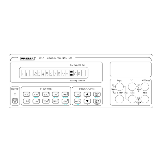
3 Quick Start _____________________________________________________________________________________________________________________________________ 3.11 Display The display can be changed and configured in the menu "Device, Display", format. Display with Settings REAR MATH FILT AUTO TRIG STORE ADR Figure: Display with Settings Selecting with Menu "Device, Display, Settings". Meaning of the Settings Settings Bedeutung REAR... -
Page 31: Display With Mathematics
Display _____________________________________________________________________________________________________________________________________ Display with Mathematics REAR MATH FILT AUTO TRIG STORE ADR Figure: Display with Mathematics Selection with "Menu Device, Display, Math". Abbreviation Meaning Offset x - a Linearization ax + b Ratio x / a % Deviation 100 * (x - a) / a Table: Meaning of the Mathematics Abbreviations Display with Channel REAR... -
Page 32: Display With Time Counter
3 Quick Start _____________________________________________________________________________________________________________________________________ The last two digits in the display show the channel number. Display with Time Counter REAR MATH FILT AUTO TRIG STORE ADR Figure: Display with Time Counter Selection with "Menu Device, Display, Sec Counter". The last two digits are counting the seconds for measurement times of more than 2s. 3-11... - Page 33 Display _____________________________________________________________________________________________________________________________________ 3-12...
-
Page 34: Manual Operation
4 Manual Operation _____________________________________________________________________________________________________________________________________ 4 Manual Operation 4.1 Keypad The user friendly design of the front panel permits quick and effective working with this instrument. On the one hand the keyboard provides direct access to important functions of the instrument such as measuring function and range setting, preselection of the measuring time and activation of a mathematical program. -
Page 35: The Function Field
Keypad _____________________________________________________________________________________________________________________________________ The Function Field Key function ON/OFF (Standby) Switches the processor section of the instrument on and off. In standby mode the analog electronic circuits are still powered up, i.e. the instrument is ready sooner for operation with full accuracy after switch-on. -
Page 36: The Range / Menu Field
4 Manual Operation _____________________________________________________________________________________________________________________________________ The Range / Menu Field Key function TIME The measuring time and thus the resolution can be changed in conjunction with the cursor keys (numerical: Dot). ZERO Starts an offset correction (zero point adjustment). (2nd + TIME) MATH Activates and deactivates calculation mode of the instrument with the preset mathematical program (numerical: "+/-"). -
Page 37: The Display Field
The Display Field _____________________________________________________________________________________________________________________________________ 4.2 The Display Field The alphanumeric liquid crystal display (LCD) shows the measurement reading, the measuring unit and a status display (or the currently active channel or the set measuring time). REAR MATH FILT AUTO TRIG STORE ADR Display Elements 1 to 10... -
Page 38: Measuring Inputs
4 Manual Operation _____________________________________________________________________________________________________________________________________ STORE not used REM for remote control ON ADR for device mode as Talker or Listener 14 to 16 Channel number display when "Channel" has been chosen in menu "Device, Display". Is active only when the measuring points scanner is activated. -
Page 39: Limiting Data For The Measuring Inputs
Measuring Inputs _____________________________________________________________________________________________________________________________________ The signal which is to be measured should always be connected in such a way that the lead closest to ground potential is connected to the black input socket (LO) and the line with the higher potential is connected to the red input socket (HI). The display then shows a reading with positive sign. -
Page 40: Setting The Measuring Functions
4 Manual Operation _____________________________________________________________________________________________________________________________________ 4.4 Setting the Measuring Functions All measuring functions are selected with a single keystroke. Period duration, Vac+dc and Iac+dc must be activated by first pressing the 2 . The selected measuring function appears in the display immediately after pressing the key. The first reading is displayed after elapse of the set integration time plus an internal waiting time. -
Page 41: Channel Selection For 5017Sc
Channel Selection for 5017SC _____________________________________________________________________________________________________________________________________ 4.6 Channel Selection for 5017SC The channels of the built-in measuring points scanner can be selected in two ways: 1st possibility Keypress Display / Action CHAN: 2 + MATH increases the channel number by one decreases the channel number by one terminates the entry and switches on the desired channel MENU... -
Page 42: Offset Correction
4 Manual Operation _____________________________________________________________________________________________________________________________________ 4.7 Offset Correction An offset value produced by thermoelectric EMFs or by the resistance of the measuring leads can be corrected digitally with the "ZERO" (2nd + ) -KEY. TIME Further details for this function are given in chapters "Calibration" and "Operating Instructions". -
Page 43: Navigating In The Menu Structure
Navigating in the Menu Structure _____________________________________________________________________________________________________________________________________ The structure of the menu is described in the following table: 1 MATHEMATICS 2 CONFIGURE 3 DEVICE 1*Offset 1 Start Mode 1 Contrast N Ofs=x-a 2 Filter 2 Interface 1 IEEE-488 a=+0.0000000E+0 1*Auto Filter 1 Address 2 ax+b 2 Fast Auto Filt... -
Page 44: Mathematical Programs
4 Manual Operation _____________________________________________________________________________________________________________________________________ 4.9 Mathematical Programs The mathematical programs are used to convert the displayed measurement reading according to a specified formula. Selection / Manual Control The manual control procedure is as follows: Keypress Display / Action MENU IN KEY If this display does not appear, press the until it appears. -
Page 45: Meaning Of The Mathematical Programs
Mathematical Programs _____________________________________________________________________________________________________________________________________ Meaning of the Mathematical Programs Mathematical Program Conversion Meaning 1 Offset (Ofs) Display = x - a Subtraction of a constant 2 ax+b (Lin) Display = ax + b Linearization of the measuring range 3 Ratio (Rto) Display = x / a Ratio display 4 %Deviation (Dev) -
Page 46: The Menu "Configure
4 Manual Operation _____________________________________________________________________________________________________________________________________ 4.10 The Menu "Configure" Start Mode / Trigger Mode This menu activates start mode. Triggering can be performed manually or via the external trigger socket. Keypress Display / Action MENU IN KEY If this display does not appear, press the until it appears. -
Page 47: Automatic Filter (Auto Filter)
The Menu "Configure" _____________________________________________________________________________________________________________________________________ Automatic Filter (Auto Filter) The automatic filter calculates the moving average over ten readings and additionally the difference between the last two successive readings, comparing this result with a difference value preset in the factory (depending on measuring range, function and time). -
Page 48: Filter Selection
4 Manual Operation _____________________________________________________________________________________________________________________________________ Filter Selection Keypress Display / Action MENU IN KEY If this display does not appear, press the until it does appear. MENU IN KEY MENU IN KEY Activates / deactivates the automatic filter with the MENU IN KEY Activates / deactivates the average value filter with the MENU... -
Page 49: Power-Up Status
The Menu "Configure" _____________________________________________________________________________________________________________________________________ Power-Up Status The following information items are saved in the power-up status: • The measuring function for each channel • The measuring range for each channel • The measuring time (resolution) for each channel • The filter setting •... -
Page 50: The Menu "Device
4 Manual Operation _____________________________________________________________________________________________________________________________________ 4.11 The Menu "Device" Technical hardware settings such as temperature sensor, interface preselection, LCD contrast and scanner setting are made in this menu. Setting the Contrast Keypress Display / Action MENU IN KEY If this display does not appear, press the until it does appear. -
Page 51: Preselecting The Interface
The Menu "Device" _____________________________________________________________________________________________________________________________________ Preselecting the Interface The 5017 is equipped with a RS232 serial data interface and the IEEE-488 interface. The interface which is to be activated can be set in this menu. Keypress Display / Action MENU IN KEY If this display does not appear, press the until it does appear. -
Page 52: Preselecting The Command Set For Remote Control
4 Manual Operation _____________________________________________________________________________________________________________________________________ Table: Setting the RS232 interface The possible handshake modes for the RS232 interface are: • Xon / Xoff • RTS / CTS (needs a special cable, see ‘Accessories’ No. 3017) • no Handshake Preselecting the Command Set for Remote Control The 5017 can be remoted with different command sets: •... -
Page 53: Selecting The Temperature Sensor
The Menu "Device" _____________________________________________________________________________________________________________________________________ Selecting the Temperature Sensor You have the choice between several different platinum resistance thermometer sensors: Pt10, Pt25, Pt100, Pt500, Pt1000. Keypress Display / Action MENU IN KEY If this display does not appear, press the until it does appear. -
Page 54: Activating The Loudspeaker
4 Manual Operation _____________________________________________________________________________________________________________________________________ Activating the Loudspeaker Keypress Display / Action MENU IN KEY If this display does not appear, press the until it does appear. MENU If this display does not appear, press the until it does appear. MENU IN KEY The loudspeaker is now active. - Page 55 The Menu "Device" _____________________________________________________________________________________________________________________________________ The following display formats can be selected: 1 Mathematics REAR MATH FILT AUTO TRIG STORE ADR Condition: Mathematical program is switched on. 2 Channel REAR MATH FILT AUTO TRIG STORE ADR Condition: 5017SC and internal connector plugged into scanner. 3 Sec.
-
Page 56: Setting The Scanner Mode
4 Manual Operation _____________________________________________________________________________________________________________________________________ Setting the Scanner Mode Keypress Display / Action MENU IN KEY If this display does not appear, press the until it does appear. MENU IN KEY If this display does not appear, press the until KEYS it does appear. -
Page 57: Error Messages
Error Messages _____________________________________________________________________________________________________________________________________ 4.12 Error Messages Overflow Measuring range overflow Sensor? Resistance of the sensor overshoots/undershoots the defined range Div/0 Division by zero in a mathematical function Br. wires Open source line in 4-wire resistance measurement Offset too high Offset too large after pressing the zero key Ω/4: Source or Sense are not connected with the right Polarity? polarity... -
Page 58: Remote Control
5 Remote Control _____________________________________________________________________________________________________________________________________ 5 Remote Control This chapter describes operation of the 5017 via the IEEE-488 and RS232 interface in remotely controlled measuring systems. This instrument supports both interface types: IEEE-488 and RS232 5.1 Configuration Some manual configurations must be made to enable operation of the 5017 via one of the two interfaces IEEE-488 or RS232. -
Page 59: Configuring The Ieee-488 Interface
Configuration _____________________________________________________________________________________________________________________________________ End Detection under RS232 The end of a transmitted or received message is designated with a line feed character "LF" in RS232 data transmission. Configuring the IEEE-488 Interface The device address and the terminator character of the messages (ASCII strings) are of importance for programing and data transmission in communication between the control computer and the 5017. -
Page 60: General Information Concerning Remote Control
SRQ 5.3 Special Features for the RS232 Interface The DMM 5017 is directly sending measurement values when opening the RS232 interface. If this is not wanted, the command ‘CN0’ can be send from the PC. Then... -
Page 61: Capabilities Of The Ieee-488 Bus Interface
Capabilities of the IEEE-488 Bus Interface _____________________________________________________________________________________________________________________________________ 5.4 Capabilities of the IEEE-488 Bus Interface The IEEE computer interface has the following capabilities defined by the IEEE-488 standard: SH 1 Handshake source function AH 1 Handshake sink function TALKER function LISTENER function Remote control Reset function Initiate function... -
Page 62: Rs232 / Ieee-488.2 Common Commands
5 Remote Control _____________________________________________________________________________________________________________________________________ 5.5 RS232 / IEEE-488.2 Common Commands In addition to the 488.1 commands, the 5017 also understands common commands according to the IEEE-488.2 standard that can be used with both interfaces RS232 and IEEE-488. The common commands are transmitted to the 5017 as ASCII character string which must always start with an asterisk "*". -
Page 63: Ese Standard Event Status Enable Command
RS232 / IEEE-488.2 Common Commands _____________________________________________________________________________________________________________________________________ *ESE Standard Event Status Enable Command The command "*ESE <Number> " sets the contents of the Standard Event Enable Register (event register mask). The parameters thereby have no effect. Number Meaning for the Standard Event Enable Register Resets the register (Bit 1) Service Request (Bit 0) Operation Completed (OPC) is set... -
Page 64: Idn? Identification Query
5 Remote Control _____________________________________________________________________________________________________________________________________ *IDN? Identification Query The command "*IDN?" queries the identification designation of the 5017. Read-out produces a character string with the following format: "PREMA GmbH,5017 DIGITAL MULTIMETER,0,<year>-<week>-<Number>" with <year> Year of software version <week> Week of software version <Number>... -
Page 65: Sre Service Request Enable Command
RS232 / IEEE-488.2 Common Commands _____________________________________________________________________________________________________________________________________ *SRE Service Request Enable Command The command "*SRE <Number>" sets the mask for the Service Request Enable Register. The individual numbers here have the following meaning: Decimal value Contents of the Service Request Enable Register Resets the register. -
Page 66: Tst? Self Test Query
Self Test Query The command "*TST?" interrogates the result of the power-up self test of the instrument. The reply is “0“ is the self test was completed without error. If any other value is obtained, please contact PREMA GmbH. *WAI Wait-to-Continue Command The command "*WAI"... -
Page 67: Structure Of The Registers
Structure of the Registers _____________________________________________________________________________________________________________________________________ 5.6 Structure of the Registers Error/event queue SCPI Standard Event Register Status Status Byte Service Request Status Enable (Set of SRQ) Enable Operation complete & & Meas Meas & & not used Error Error & &... -
Page 68: Operation As Listener
5 Remote Control _____________________________________________________________________________________________________________________________________ 5.7 Operation as Listener The instrument must be addressed as LISTENER to prepare it for receiving commands. The instructions for doing this are contained in the user manual of the computer manufacturer. The segment ‘ADR’ in the right window of the display is lit when the instrument has been addressed as LISTENER. - Page 69 Operation as Listener _____________________________________________________________________________________________________________________________________ Temperature measurement in K Selection of the temperature sensor with x = 1 Pt10 x = 3 Pt100 x = 2 Pt25 x = 4 Pt500 x = 5 Pt1000 Query of the currently set temperature sensor Frequency Period duration Continuity check...
- Page 70 5 Remote Control _____________________________________________________________________________________________________________________________________ Integration time / Measuring time selection with x = 0 20ms x = 6 x = 1 40ms x = 7 x = 2 100ms x = 8 10 s x = 3 200ms x = 9 20 s x = 4 400ms...
-
Page 71: Display Mode
Display Mode _____________________________________________________________________________________________________________________________________ (L/zero) short format; the multimeter outputs only the first message unit (measurement data and text messages). Long format; the multimeter outputs both message units (measurement data/text messages and programing data). (Zeppelin/Otto) Offset correction on Selects a scanner channel with xx = 01 to 80 Scanner mode with x = 1 1-pole, 80 channels... - Page 72 5 Remote Control _____________________________________________________________________________________________________________________________________ character position. All superfluous characters present after D1 and the output text are ignored. If D1 "text" is sent together with other commands in the same character string, it must be the last command in the character chain. D0 switches display mode off again and the display according to the active operating mode and function appears.
-
Page 73: String Length Selection
String Length Selection _____________________________________________________________________________________________________________________________________ 5.9 String Length Selection The digital multimeter can send different length messages to the computer whereby the desired message length is selected with L0 or L1. The latest measurement reading is returned if the computer sends the command L0. The status information is not output in response to L0. -
Page 74: Description Of The Message Record Sent
5 Remote Control _____________________________________________________________________________________________________________________________________ Only the first message unit is transmitted when the short string is requested (command “L0"). The status information (2nd message unit) is not sent in this case. Description of the Message Record Sent The following table gives an overview of the possible lengths of the message record depending on the selected operating mode. -
Page 75: Table Of Device Messages Sent By The Multimeter
Operation of the Digital Multimeter as TALKER _____________________________________________________________________________________________________________________________________ Table of Device Messages sent by the Multimeter The device message outputs the following characters to designate the instrument status or the instrument settings: 1st character 14th character 40th character + End +x.xxxxxxxxE+xMRVDPxxAxRxFxTxDxSxQxMxxB00 - 000000000 -0CRVA 01 0 1 0 0 0 0 0 01 01 0 .. -
Page 76: Meaning Of The Transmitted Characters
5 Remote Control _____________________________________________________________________________________________________________________________________ Meaning of the Transmitted Characters Position (first, last character) of the device message ( 1, 1) "+" positive sign of the mantissa "-" negative sign of the mantissa ( 2, 10) "x" 8-digit mantissa or text message, Numerical range ".00000000 - 99999999"... - Page 77 Operation of the Digital Multimeter as TALKER _____________________________________________________________________________________________________________________________________ (18, 20) "Pxx" Mathematical program No. xx selected "P01" Offset "P02" ax + b "P03" Ratio "P04" % Deviation "P05" dB "P06" dBm (21, 22) "A0" Autoranging switched off "A1" Autoranging switched on (23, 24) "Rx"...
- Page 78 5 Remote Control _____________________________________________________________________________________________________________________________________ (29, 30) "Dx" Display mode x=0 Display mode switched off x=1 Display mode switched on (31, 32) "Sx" Start mode x=0 Start mode switched off x=1 Start mode switched on x=2 Start mode on, start with trigger line or button (33, 34) "Qx"...
-
Page 79: Error Messages
Error Messages _____________________________________________________________________________________________________________________________________ 5.12 Error Messages Error 01 Overflow Measuring range overflow Sensor? Resistance of the sensor overshoots/undershoots the defined range Error 02 Div/0 Division by zero in a mathematical function Error 03 Br. wires Open source line in 4-wire resistance measurement Error 04 Offset too high Offset too large after pressing the zero key (302) -
Page 80: Compatibility
5 Remote Control _____________________________________________________________________________________________________________________________________ 5.13 Compatibility The customer can also select a command set which is compatible to the DMM 4001/5001/6001 or to the DMM 6047 / 6048 in the menu ‘Device’, ‘Interface’, ‘Command Set’. 5017 as Listener 5017 6001/4001 6047 Remarks NOT through Scanner inputs... - Page 81 M20 instead of front panel input NVxx..x NVxx..x NVxx..x 7, 8 or 9 characters NV“pp..p“ PIN no. has to be entered manually only 0...7 with 6001 *IDN? 6001 sends back ‘DMM 5017' Table: Compatibility for 6001 and 6047/6048 as listener 5-24...
-
Page 82: 5017 As Talker
5 Remote Control _____________________________________________________________________________________________________________________________________ Non Compatible • Math programs • Memory (‘STxx’, ‘RCxx’) • Analog Display (‘AF’) 5017 as Talker The first message unit Length Remarks 6001/6048 compatible 5017 format as displayed 123.45678E+0 123.45678E+0 6001 in basic units 123.4567E+0 1.234567E+2 6048 in basic units 123.456789E+0... - Page 83 Compatibility _____________________________________________________________________________________________________________________________________ The Statusbyte BitNo. 5017 6001 6047 remarks Bit-compatible, EOC = End of Conversion Error Error Error Bit-compatible incompatible incompatible Bit-compatible Button Button Button Bit-compatible Bit compatibility results only on querying solely the respective bit. The decimal value of the status byte is incompatible. Selecting function, range and integration time The range and the integration time are stored separately for every function, function range and integration time are stored for every channel.
-
Page 84: Difference Between 5017 And 6001 Concerning Hardware
5 Remote Control _____________________________________________________________________________________________________________________________________ Difference between 5017 and 6001 concerning hardware Function DMM 5017 / 5017SC DMM 6001 / 6001SC, 4001/4001SC Display 7½ digit for Vdc and Ohms 6½ digit LED matrix Full scale 30 100 000 for Vdc and Ohms... - Page 85 Compatibility _____________________________________________________________________________________________________________________________________ 5-28...
-
Page 86: Calibration
Within that year, specification data are guaranteed to be valid. 6.2 PREMA Calibration Service You can have your unit calibrated by PREMA or by a local calibration lab. Call the telephone number indicated on the front of the manual, in order to obtain information about the price and duration of this service. - Page 87 Automated Calibration _____________________________________________________________________________________________________________________________________ The calibration of the 5017 can be automated with a computer and a Multifunction Calibrator. All measurement functions can be remotely controlled by the computer, through a special command set (for more information see chapter “Remote Control”). Calibration can normally be carried out entirely by remote control, without any need to manually adjust potentiometers or capacitors.
-
Page 88: Important Steps Prior To Calibration
6 Calibration _____________________________________________________________________________________________________________________________________ 6.5 Important Steps prior to Calibration The following items must be taken care of before the calibration procedure is started: The calibration environment should be at a stable temperature of at least 18°C (64.4°F), but no more than 28°C (82.4°F). Ideally, the temperature should be 23 ±1°C (73.4°F). -
Page 89: Pin Number And Calibration Switch
PIN Number and Calibration Switch _____________________________________________________________________________________________________________________________________ 6.6 PIN Number and Calibration Switch Calibration can be protected against accidental or incorrect calibrations, through the use of a rear calibration switch and a special PIN number. The calibration button is located on the rear panel, and can be pushed with a pointed object (pen, pencil, paper clip, etc.). -
Page 90: Changing The Pin Number
6 Calibration _____________________________________________________________________________________________________________________________________ By following the steps described above, each measurement function and measurement range is calibrated. The following measurement functions and ranges must be calibrated: Measurement Function Measurement Ranges 300mV, 3V, 30V, 300V, 1000V 200mV, 2V, 20V, 200V, 1000V 200µA, 2mA, 20mA, 200mA, 2A 200µA, 2mA, 20mA, 200mA, 2A Ω4W... -
Page 91: Offset Correction
Offset Correction _____________________________________________________________________________________________________________________________________ 6.7 Offset Correction An offset correction must be carried out for the following measurement functions and ranges: Measurement Function Measurement Ranges 300mV, 3V, 30V, 300V, 1000V 200mV, 2V, 20V, 200V, 700V 300µA, 3mA, 30mA, 300mA, 2A 200µA, 2mA, 20mA, 200mA, 2A Ω2W 300Ω, 3kΩ, 30kΩ, 300kΩ, 3MΩ, 30MΩ... -
Page 92: Calibrating Dc Voltage
6 Calibration _____________________________________________________________________________________________________________________________________ 6.8 Calibrating DC Voltage Offset Correction for DC Voltage To carry out the Offset Correction for DC Voltage measurements, a short-circuit must be applied to the V-Ω front input connectors (Accessory No. 3016). After triggering a zero-point correction by pressing the zero key, an Offset Measurement is carried out for the currently set measurement range. -
Page 93: Calibration Of Resistance Ranges
Calibration of Resistance Ranges _____________________________________________________________________________________________________________________________________ 6.9 Calibration of Resistance Ranges Offset Correction When zeroing two-wire resistance measurement, the VΩ-Hi and VΩ-Lo connectors should be short-circuited, by connecting a short-circuit terminator to these front input connectors, instead of the resistance to be measured. In four-wire resistance measurement, the real offset value is determined, by using two short-circuit terminators (Accessory No. -
Page 94: Calibration Of Ac Voltage
6.12 Calibration of Temperature 1. Preparations a) Warmup-period: The DMM 5017 to be calibrated should have run for at least 1h. 2. TEMP-Function: ZERO Offset Correction a) Insert a four-wire shorting-bridge at the input of the DMM5017, i.e. shorten the four DMM 5017 Volt/Ohm-inputs - Sense and Source - HI against LO and both pairs against each other. - Page 95 Calibration of Temperature _____________________________________________________________________________________________________________________________________ specified. But performing this sequence of operations corrects for the OHM- function ZERO-offset, with the OHM-function implemented as fundamental function for the Temperature-measurement with RTDs. That means here, the DMM5017 display ‘Sensor ?’ is not an error ! c) Press the following buttons in sequence to select the RTD-type (e.g.
-
Page 96: Storing Calibration Values
6 Calibration _____________________________________________________________________________________________________________________________________ 4. TEMP-Function: Extended list of RTDs Press the following buttons in sequence to select the recently calibrated RTD, e.g. Pt100 : Menu/↵ A 3 DEVICE ↵ A 3 Temp. Sensor ↵ A 6 Pt100 ↵ Menu/OUT. Cal. Cal. -
Page 97: Operating Instructions
7 Operating Instructions _____________________________________________________________________________________________________________________________________ 7 Operating Instructions 7.1 DC Voltage Measurement Input Resistance in DC Voltage To make use of the high linearity of the measurement process, the input resistance for voltage measurements up to 3V is set very high (>10GΩ). In this range, the unit al- lows precise measurements, with a maximum load error of 1ppm, even at measure- ment objects with an internal resistance of 1kΩ. -
Page 98: Series Mode Suppression
DC Voltage Measurement _____________________________________________________________________________________________________________________________________ The influence of the source resistance is visualized in the following diagram: Figure: Influence of source resistance on the measurement unit Input Resistance of the Multimeter ( 10MΩ or >1GΩ ) = Source Resistance of the Measurement Object Voltage of the Measurement Object The error, in %, of a measurement, is calculated as follows: ×... -
Page 99: Common Mode Suppression
7 Operating Instructions _____________________________________________________________________________________________________________________________________ That is why, in the 5017 a PLL circuit (Phase Locked Loop) is used to synchronize the measurement time with the period of the main line frequency. An integer multiple of the mains period is always contained in the measurement time. Due to the fully integrating measurement process, the positive and negative half- waves of line voltage are neutralized. -
Page 100: Noise Effects Through Inductive Interferences
DC Voltage Measurement _____________________________________________________________________________________________________________________________________ The sketch shows the possible thermal voltage sources in a measurement circuit, which can exist at an external connection point (Contact 1/2), but can also occur in the connectors of the measurement unit. It is always important to carry out all connections with the same material, or at least to use materials, that produce very small thermal voltages, when they are put in contact with each other. -
Page 101: Resistance Measurement
7 Operating Instructions _____________________________________________________________________________________________________________________________________ 7.2 Resistance Measurement The resistance measurements of the 5017 are carried out through the DC Current method in a 2-wire or 4-wire connection. A constant current (I) is forced through the resistance to be measured (R); the same current simultaneously flows through a known internal range resistance. - Page 102 Resistance Measurement _____________________________________________________________________________________________________________________________________ If an Offset Correction is not carried out, a measurement value R m is obtained, which Diagram: Principle of 2-wire resistance measurement is composed of the sum of all the resistances that exist in the measurement circuit (measurement path), and is too high by the lead resistance.
-
Page 103: Four-Wire Resistance Measurement
7 Operating Instructions _____________________________________________________________________________________________________________________________________ Four-Wire Resistance Measurement To avoid the measurement problems that are produced by lead resistance, the four- wire arrangement is used for the measurement of small resistances (see diagram be- low). Diagram: Principle of 4-wire resistance measurement The measurement current I is forced through the ‘external’... -
Page 104: Power Dissipation In The Resistors
AC Voltage Measurement _____________________________________________________________________________________________________________________________________ It is also of advantage to use an integration time greater than 1s, since the greater length of measurement signal integration serves to suppress noisy scatter. Power Dissipation in the Resistors An error source that is often forgotten in the measurement of resistance sensors (e.g. temperature sensors), is the power dissipation in the resistances to be measured, and thereby the self-heating that is associated with it. -
Page 105: Dc And Ac Current
7 Operating Instructions _____________________________________________________________________________________________________________________________________ In the 200V and 700V ranges, at high frequencies (200V range more than 100kHz, 700V range more than 10kHz), please make sure, that the applied AC Voltage does not surpass the RMS Value product of 10,000,000V x Hz. 7.4 DC and AC Current The 5017 Multifunction Meter carries out Current measurements through the use of precise shunt resistors. -
Page 106: Temperature Measurement
Lo-Lo of the measuring line (Ω-input) and of the current source (Ω-source-input). The 5017 linearizes the temperature for Pt10, Pt25, Pt100, Pt500 and Pt1000 sensors. Ready mounted Pt100 sensors are available from PREMA with handle and gold- plated banana plugs for four-wire connection to the 5017 ( see accessories). -
Page 107: Construction
300mV to 3V. It is therefore suited for highly precise DC Voltage and Resistance measurements. Current Shunts Reference Micro- Front or Integr. AD Converter DC Attenuator con- Rear Connectors (PREMA-ASIC) or Scanner troller Current Source for Ohm Measurements Relais Control (PREMA-ASIC) Diagram: Input Circuit for DC Values and Resistance... -
Page 108: Integrating A To D Converter
For the highest possible resolutions, the AD converter is an integrating converter whereby the direct voltage is converted to a sequence of pulses. The PREMA Multiple Ramp Technique for analog to digital conversion (GPD #2114141, US Patent 3765012) is the basis for a dependable Digital Multimeter with exceptional linearity and extraordinary long-term accuracy using continuous integra- tion of the measured signal without distorting interruptions. -
Page 109: Mains Synchronization
(aging). The converter is composed of PREMA’s customized IC, the external reference, the series resistors, and the integration capacitor. The use of ASICs represents an important advantage here, since space is saved on the one hand, and the possibility of component failure is further reduced on the other hand. -
Page 110: Reference
Integrating A to D Converter _____________________________________________________________________________________________________________________________________ Reference The integrating AD converter must be wired up with an external reference. The prop- erties of this reference ultimately determine the long-term stability of the unit. That is why only selected components, which have been tested, and aged, over a long period of time, are put to use in the 5017. -
Page 111: Measurement Of Ac Voltage
An attenuation path was devised for the measurement of AC Voltages, which pro- vides high band widths and sufficient measurement speed. Reference RMS to DC Integr. Converter Current Converter (PREMA-ASIC) Shunts Micro- Front or con- Rear Connectors Attenuator or Scanner... -
Page 112: Application Of Microprocessors
Application of Microprocessors _____________________________________________________________________________________________________________________________________ 8.4 Application of Microprocessors A variety of microprocessors come into use in the 5017. In order to support a certain level of modularity in the individual systems, it is desir- able to make the modules as autonomous as possible. This is achieved through diverse microprocessors of varying capacities. -
Page 113: Power Management
8 Construction _____________________________________________________________________________________________________________________________________ Power Management The Power Management processor is directly responsible for all the functions that have to do with the incoming power voltage, as well as with the voltage supply to the individual modules. The Standby switch has to be monitored to prevent data loss. The power manager makes sure, that all actual settings are stored in the EPROM after switch-off the 5017 with the Standby. -
Page 114: Ports
Ports _____________________________________________________________________________________________________________________________________ 8.5 Ports You will find information about the connectors and their pin assignments in chapter 9, “Technical Specifications”. Display The built-in display is an alphanumerical LC display with 16 easy to read characters. In order to improve the contrast, the display is backlighted. The contrast can be set in the menu. -
Page 115: Measurement Inputs
8 Construction _____________________________________________________________________________________________________________________________________ 8.6 Measurement Inputs The 5017’s front and rear panel are both equipped with five safety connectors, to which measurement signals can be connected. In order to reduce thermoelectric volt- age and contact resistance, the connectors are composed of high-grade copper-tellur. For precise measurements of even the smallest voltages and resistances, you should also use measurement leads with connectors composed of copper-tellur (see Accesso- ries). -
Page 116: 5017Sc
5017SC _____________________________________________________________________________________________________________________________________ 8.8 5017SC The 5017SC is equipped with a 40 channel scanner, that allows to connect up to 80 channels 1-pole to the 5017SC. The connection is provided through the two 50-pole Sub-D connectors on the rear panel of the 5017SC. Please refer to chapter 9, "Technical Specifications"... -
Page 117: Technical Specifications
9 Technical Specifications _____________________________________________________________________________________________________________________________________ 9 Technical Specifications All error limits and stability specifications are given according to a calibration standard traceable to the “Physikalisch Technische Bundesanstalt (PTB)” (German National Bureau of Standards). The ambient temperature at the time of calibration was 23°C ±... - Page 118 DC Voltage _____________________________________________________________________________________________________________________________________ ACCURACY ( 1 Year) 1),3),4) ± (% of Reading + % of Full Scale) 1 Year 23°C±5°C Range %Rdg. %F.S. ±300mV 0.003 0.0002 ±3V 0.002 0.0002 ±30V 0.002 0.0002 ±300V 0.003 0.0004 ±1000V 2) 0.004 0.0010 The values specified above assume that the measuring time dependent readout span is set large enough to permit readout with the accuracy stated.
-
Page 119: Technical Specifications
9 Technical Specifications _____________________________________________________________________________________________________________________________________... - Page 120 (Low-Ohm connection from Shield to black “V, Ω−Lo" connector, with 1kΩ in the "Lo" Lead) MEASUREMENT PAUSES after Range, Function, or Channel switch: 100ms MEASURING METHOD fully integrating PREMA Multiple Ramp Method (DBP.Nr.2114141, (US-Pat. No. 3765012) POLARITY CHANGE automatic, without measurement pause...
- Page 121 9 Technical Specifications _____________________________________________________________________________________________________________________________________ OVERLOAD LIMITS V/Ω Ω -HI against Case (Ground) ± 1000 V Peak at 60 Hz max. or ± 1000V DC V/Ω Ω -HI against V/Ω Ω -LO Input ± 300mV, ± 3V for 60 sec. ± 1000V 2) Continuous Load ±...
-
Page 122: Resistance
Resistance _____________________________________________________________________________________________________________________________________ 9.2 Resistance MEASURING METHOD..2-, 4-pole with DC measuring current 300 Ω / 3 kΩ / 30 kΩ / 300 kΩ / 3 MΩ / 30 MΩ RANGES ....... RANGE SELECTION... manual, automatic MEASUREMENT TIMES Full Scale max. Resolution 20ms / 40ms / 100ms 301 000 1 mΩ... - Page 123 9 Technical Specifications _____________________________________________________________________________________________________________________________________ TEMPERATURE COEFFICIENTS (10°C-18°C / 28°C-40°C) (0°C-10°C / 28°C-50°C) Range ±(%Rdg. + % F.S.)/°C ±(%Rdg. + %F.S.)/°C 300Ω 0.0003 + 0.0003 0.0006 + 0.0006 3kΩ 0.0002 + 0.0002 0.0004 + 0.0004 30kΩ 0.0002 + 0.0002 0.0004 + 0.0004 300kΩ...
-
Page 124: Ac Voltage
AC Voltage _____________________________________________________________________________________________________________________________________ 9.3 AC Voltage CONVERSION METHOD True RMS value with DC Voltage coupling, or pure AC Voltage RANGES ......200mV/20/20V/200V/700V 3) RANGE SELECTION... manual, automatic MEASURING TIMES Full Scale max. Resolution 100ms 199 999 1µV 0.2s - 100 s 1 999 999 100nV Range 700V... - Page 125 9 Technical Specifications _____________________________________________________________________________________________________________________________________ OVERLOAD LIMITS V/Ω Ω -HI against Case ± 1000 V Peak at 60 Hz max. or ± 1000V DC Voltage V/Ω Ω -HI against V/Ω Ω -LO 200mV-, 2V-Range for 60 sec. ± 1000V Peak with the limit of 1*10 *V*Hz Continuous Load...
- Page 126 AC Voltage _____________________________________________________________________________________________________________________________________ 3) max. 100Vrms on rear panel connectors for Model 5017SC 4) the mode Vac+dc must be activated for AC voltages with a frequency lower than 50Hz 9-10...
-
Page 127: Dc Current
9 Technical Specifications _____________________________________________________________________________________________________________________________________ 9.4 DC Current RANGES ......±200µA, ±2mA, ±20mA, ±200mA, 2A MEASUREMENT TIMES Full Scale max. Resolution 20ms / 40ms / 0.1s 201 000 1 nA 0.2s - 100s 2 010 000 100 pA STABILITY 24 Hours, 23°C ± 1°C 1, 2) ±... - Page 128 DC Current _____________________________________________________________________________________________________________________________________ TEMPERATURE COEFFICIENT (10°C-18°C and 28°C - 40°C) ±(0.001%Rdg. + 0.0002% F.S.)/°C (0°C-10°C and 40°C - 50°C) ±(0.002%Rdg. + 0.0004% F.S.)/°C BURDEN VOLTAGE AND INSTRUMENT SHUNT Range Burden Voltage Instrument Shunt 1000 Ω 200µA 350mV 100 Ω 350mV 10 Ω...
-
Page 129: Ac Current
9 Technical Specifications _____________________________________________________________________________________________________________________________________ 9.5 AC Current CONVERSION METHOD..True RMS value with DC Current coupling or pure AC Current RANGES ....... 200µA / 2mA / 20mA / 200mA / 2A RANGE SELECTION... manual, automatic MEASUREMENT TIMES Full Scale max. Resolution 100ms 201 000 0.2s - 100 s... -
Page 130: Temperature
Temperature _____________________________________________________________________________________________________________________________________ SETTLING TIME....100ms at 0.1% MEASUREMENT PAUSES... after Range, Function, or Channel switching, 300ms OVERLOAD LIMITS .... input protection (3A fast blow out fuse) Personal Safety: A-Hi to Ground max. 60Vpk A-Lo to Ground max. 60Vpk 1) Sine Signal larger than 5% of the Full Scale; V/Ω/LO connected to Ground. 2) the specs are to be multiplied with factor 3 for currents >... - Page 131 9 Technical Specifications _____________________________________________________________________________________________________________________________________ VOLTAGE ON OPEN CLAMPS ca. 5V MEASUREMENT TIMES..100ms to 100s MEASUREMENT PAUSES..after Range, Function, or Channel switches: 100ms ACCURACY 1) Sensors Stability 24h, 23±1°C Accuracy 1 Year, 23±5°C ± (%Rdg. + °C) ± (%Rdg. + °C) Pt10 0.002% + 0.03°C 0.007% + 0.04°C...
-
Page 132: Frequency And Period
Frequency and Period _____________________________________________________________________________________________________________________________________ 9.7 Frequency and Period MEASUREMENT METHOD..Reciprocal Enumeration Method FREQUENCY RANGE....Vac: 0.2 Hz to 1 MHz Iac: 0.2 Hz to 10 kHz PERIOD RANGE......Vac: 40 µs to 5 s Iac: 100 µs to 5 s INPUT SIGNAL...... -
Page 133: Special Functions
9 Technical Specifications _____________________________________________________________________________________________________________________________________ 9.8 Special Functions Continuity Check with acoustic signal with threshold of 50 Ω. • • Math Programs Offset ax + b Ratio %Deviation • Filter Functions Moving Average with 10 readings Automatic Filter with window • Storage of Instrument Settings Store power-on settings Load factory settings... -
Page 134: Scanner With Model 5017Sc
Scanner with Model 5017SC _____________________________________________________________________________________________________________________________________ 9.9 Scanner with Model 5017SC CHANNELS ......80 Channels 1-pole, 40 Ch 2-pole, 20 Ch 4-pole SWITCHING METHOD ..bi-stable mechanical relays MEAS. FUNCTIONS ....Voltage, Resistance, Temp., Hz THERMO VOLTAGE ... typ. ± 1µV, max. 2µV after 1.5h warm-up time MAX. -
Page 135: Pin Assignment Of The Scanner
9 Technical Specifications _____________________________________________________________________________________________________________________________________ Pin Assignment of the Scanner Scanner Input 1 Channel Channel Channel PIN No. Channel Channel Channel PIN No. 4-pole 2-pole 1-pole 4-pole 2-pole 1-pole 01 SHi 01 Hi 01 Hi 06 SHi 11 Hi 21 Hi 01 SLo 01 Lo 02 Hi... - Page 136 Scanner with Model 5017SC _____________________________________________________________________________________________________________________________________ Scanner Input 2 Channel Channel Channel PIN No. Channel Channel Channel PIN No. 4-pole 2-pole 1-pole 4-pole 2-pole 1-pole 11 SHi 21 Hi 41 Hi 16 SHi 31 Hi 61 Hi 11 SLo 21 Lo 42 Hi 16 SLo 31 Lo...
-
Page 137: Ieee-488 Interface
9 Technical Specifications _____________________________________________________________________________________________________________________________________ 9.10 IEEE-488 Interface OUTPUT INFORMATION measurement result, function, range, measurement time, calculation result and other device settings. INPUT INFORMATION function, range, measurement time, start command, calibration set-point, math program and constants, display text and other device settings. ADDRESS ...... - Page 138 IEEE-488 Interface _____________________________________________________________________________________________________________________________________ PIN ASSIGNMENTS IEEE-488 INTERFACE Data Bus: DIO 1 DIO 5 DIO 1-DIO 8 Data Bits 1-8 DIO 2 DIO 6 DIO 3 DIO 7 DIO 4 DIO 8 Data Transfer GND (DAV) Control Bus NRFD GND (NRFD) NDAC GND (NDAC) Data Valid...
-
Page 139: Rs232 Serial Interface
9 Technical Specifications _____________________________________________________________________________________________________________________________________ 9.11 RS232 Serial Interface DATA FORMAT 8N1 (8 data bits, no parity, 1 stop bit) BAUD RATE 9600 Bd CONNECTOR TYPE 9-pin Sub-D connector HANDSHAKE selectable: - Xon/Xoff - RTS/CTS - no handshake PIN ASSIGNMENTS: PIN-No. Orientation Signal Description Input... - Page 140 RS232 Serial Interface _____________________________________________________________________________________________________________________________________ PIN Assignment RS232 Cable 9-24...
-
Page 141: Trigger Interface
9 Technical Specifications _____________________________________________________________________________________________________________________________________ 9.12 Trigger Interface CONNECTOR TYPE 9-pin SUB-D Connector NUMBER OF LEADS 8 lines (4 used) INPUT VOLTAGE Active Low VIH Min. -0.5V Max. 0.8V Min. 2.0V Max. 5.5V PIN ASSIGNMENTS OF TRIGGER INTERFACE Signal Trigger Reading PIN 1 = Ground 9-25... -
Page 142: Eu Conformity
EU Conformity _____________________________________________________________________________________________________________________________________ 9.13 EU Conformity The EU Declaration of Conformity for the 5017 certifies that this multimeter conforms to the pertinent requirements of the relevant EU directives and standards. EMC Compliance Tests The following EMC (EMC = Electromagnetic Compatibility ) compliance tests have been carried out conforming to the EMC directive 89/336/EWG. -
Page 143: Measurement Of Emi Immunity
9 Technical Specifications _____________________________________________________________________________________________________________________________________ Measurement of EMI Immunity Conforming EN 50082-1, European Standard, Electromagnetic Compatibility - Generic Immunity Standard Generic Standard Class: Residential, Commercial, or Light Industry. Additional 5017 specifications under EMC test conditions ENV 50140 EMC Immunity against radiated EMI (Electromagnetic Interference). EMC Basic Directive, 30-1000MHz. -
Page 144: General
General _____________________________________________________________________________________________________________________________________ 9.14 General SECURITY complies with EN 61010, Ground is connected to the case. WARM-UP TIME ..... 20 min. to reach 1-Year Accuracy, 1h to reach 24h Stability. ENVIRONMENT TEMPERATURE Operation...... 10°C to 45°C Storage......-25°C to 60°C RELATIVE HUMIDITY Operation...... - Page 145 9 Technical Specifications _____________________________________________________________________________________________________________________________________ DIMENSIONS Height ......about 96 mm / 3.8 inch with feet about 89 mm / 3.5 inch without feet Width ......about 225 mm / 8.86 inch Depth ......about 375 mm / 14.7 inch DIMENSIONS OF DELIVERED PACKAGE (CARTON) Height ......
-
Page 146: Accessories
10 Accessories _____________________________________________________________________________________________________________________________________ 10 Accessories 10.1 Adaptercard (3110) The adaptercard can be connected externally to the 50-wire Sub-D connector on the rear of the 5017 when it is equipped with a scanner (5017SC). This card contains screw terminals for the incoming wires and so it is useful when you need to change the configurations of sources being scanned. -
Page 147: Mating Plug For Sub-D (6000/03)
Mating Plug for Sub-D (6000/03) _____________________________________________________________________________________________________________________________________ 10.2 Mating Plug for Sub-D (6000/03) A 50-wire subminiature type D connector can be used for each set of 10 channels (4- pole). This connector has solder connections for each wire and a cable outlet for round cables up to 12 mm diameter. -
Page 148: Set Of Short Circuit Plugs (3016)
Dimensions in cm : about 27 x 39 x 15 (W x H x D) 10.9 Accessories for the IEEE488 Bus An interface card in the PC is necessary to remote control the 5017. PREMA offers the following IEEE488 interface card for PC/AT/XT and compatibles: 5025 IEEE-488 Interface Card PC2A for PC XT/AT incl. -
Page 149: 19-Inch Rack Mounting Kit (5021 G)
19-inch Rack Mounting Kit (5021 G) _____________________________________________________________________________________________________________________________________ 10.10 19-inch Rack Mounting Kit (5021 G) Complete Slide-In module to mount a 5017 into a 19-inch rack. Height 2 HU. The rack mounting kit is delivered with all essential screws. An extra shield is also delivered if there is only one 5017 in use. 10-4... - Page 150 Index _____________________________________________________________________________________________________________________________________ Index AC Current • 9-11 Current DC Current • 9-10 Quickstart • 3-3 Operating Instructions • 7-9 Current Shunt • 10-3 *CLS Clear Status • 5-5 *ESE Event Status Enable • 5-6 *IDN? Identification • 5-7 *OPC Operation Completed • 5-7 Calibration •...
- Page 151 Index _____________________________________________________________________________________________________________________________________ Frequency Preselection • 4-18 Measuring Current Quickstart • 3-6 Interface select • 5-1 Resistance • 9-6 Specifications • 9-14 Intergrating AD-Converter • 8-2 Measuring function Frequency Range Isolation Setting • 4-7 Frequency • 9-14 Scanner • 9-16 Measuring inputs • 4-5 Front panel •...
- Page 152 Index _____________________________________________________________________________________________________________________________________ PIN Assignments RS232 Synchronization • 8-3 IEEE488 Interface • 9-20 Capabilities • 5-3 RS232 Interface • 9-21 Configuration • 5-1 Scanner • 9-17 RS232 Cable • 10-3 TTL I/O Interface • 9-23 RS232 interface setting • 4-18; 4- Talker mode •...
-
Page 153: Index
Index _____________________________________________________________________________________________________________________________________ Calibration • 6-6 DC Voltage • 9-2...
Need help?
Do you have a question about the DMM 5017 and is the answer not in the manual?
Questions and answers