Sign In
Upload
Download
Table of Contents
Contents
Add to my manuals
Delete from my manuals
Share
URL of this page:
HTML Link:
Bookmark this page
Add
Manual will be automatically added to "My Manuals"
Print this page
×
Bookmark added
×
Added to my manuals
Manuals
Brands
ZALMAN Manuals
Desktop
HD501
User manual
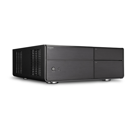
ZALMAN HD501 User Manual
Hd500 series
Hide thumbs
1
2
3
4
5
6
7
8
9
10
11
12
13
14
15
16
17
18
19
20
Table Of Contents
21
page
of
21
Go
/
21
Contents
Table of Contents
Bookmarks
Advertisement
Table of Contents
1
Cautionary Notes
2
Specifications
3
Main Unit
4
Front Panel Components
5
Installation Preparation
6
ODD Installation
7
HDD Installation
8
Cable Connections
9
Optional Fan Installation
10
Recommended Use
11
Installation Location
12
Cable Routing
Download this manual
English
Table of
Contents
Previous
Page
Next
Page
1
2
3
4
5
Advertisement
Table of Contents
Need help?
Do you have a question about the HD501 and is the answer not in the manual?
Ask a question
Questions and answers
Related Manuals for ZALMAN HD501
Desktop ZALMAN HD503 User Manual
Hd500 series (21 pages)
Desktop ZALMAN GS1000 SE User Manual
(16 pages)
Desktop ZALMAN Z12 Series User Manual
Atx mid tower (29 pages)
This manual is also suitable for:
Hd503
Table of Contents
Print
Rename the bookmark
Delete bookmark?
Delete from my manuals?
Login
Sign In
OR
Sign in with Facebook
Sign in with Google
Upload manual
Upload from disk
Upload from URL


Need help?
Do you have a question about the HD501 and is the answer not in the manual?
Questions and answers