Table of Contents
Advertisement
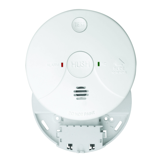
MODEL LIF5000
INSTALLATION AND USER MANUAL
LIFESAVER SMOKE ALARM IONISATION DESIGN
240VAC MAINS POWERED SINGLE STATION AND/OR INTERCONNECTABLE
(24 UNITS) IONISATION SMOKE ALARM. 9V REPLACEABLE BATTERY
BACKUP . TEST AND HUSH CONTROL AND LOW BATTERY INDICATION.
IMPORTANT: READ ALL INSTRUCTIONS BEFORE INSTALLATION.
NO USER REPLACEABLE PARTS INSIDE THIS SMOKE ALARM.
WARNING: Disconnecting smoke alarm from mounting base and/or removing the 9V battery
will render this smoke alarm inactive.
SPECIFICATION
ELECTRICAL RATING:
WARNING:
THIS SMOKE ALARM MUST ONLY BE WIRED TO A
240Vac 50Hz SINE WAVE CURRENT SUPPLY.
THE SMOKE ALARM USES AN EXTREMELY SMALL AMOUNT OF A
RADIOACTIVE ELEMENT IN THE DUAL IONISATION CHAMBER.
240VAC 50Hz, 80mA per alarm and interconnectable to
24 alarms.
Advertisement
Table of Contents

Related Manuals for Lifesaver LIF5000


Summary of Contents for Lifesaver LIF5000
- Page 1 MODEL LIF5000 INSTALLATION AND USER MANUAL LIFESAVER SMOKE ALARM IONISATION DESIGN 240VAC MAINS POWERED SINGLE STATION AND/OR INTERCONNECTABLE (24 UNITS) IONISATION SMOKE ALARM. 9V REPLACEABLE BATTERY BACKUP . TEST AND HUSH CONTROL AND LOW BATTERY INDICATION. IMPORTANT: READ ALL INSTRUCTIONS BEFORE INSTALLATION.
-
Page 2: Table Of Contents
CONTENTS RECOMMENDED LOCATIONS OF ALARMS ................MOBILE HOME INSTALLATION ......................... AVOID THESE LOCATIONS ..........................FALSE ALARMS ................................HOW TO REMOVE SMOKE ALARM FROM BASE PLATE ..........INSTALLATION ................................OPERATION, TESTING AND MAINTENANCE ................BATTERY INSTALLATION, REPLACEMENT AND TEST ..........9V TERMINAL AND REMOTE TEST & HUSH ................ -
Page 3: Recommended Locations Of Alarms
RECOMMENDED LOCATIONS OF ALARMS Locate an alarm for each separate sleeping area in the immediate vicinity of the bedrooms. Try to monitor the exit path as the bedrooms are usually far- thest from an exit. If more than one sleeping area exit, locate additional alarms in each sleeping area in the immediate vicinity bedrooms. - Page 4 RECOMMENDED LOCATIONS OF ALARMS 1.11 When mounting the alarm at the apex of a sloping ceiling it should be located at least 500mm away from the apex but should not exceed 1500mm (see diagram). 1.12 Locate smoke alarm at both ends of a bedroom hallway or large room if the hallway or room is more than 9m long.
-
Page 5: Mobile Home Installation
Do not locate your alarm in the garage - products of combustion are present when you start your automobile. Use Lifesaver Heat Alarm in this location. Do not locate your alarm in front of forced air supply ducts used for heating and air conditioning and other high air flow areas. -
Page 6: False Alarms
Avoid dusty areas, dust particles may cause smoke alarm to false alarm or fail to alarm. Use Lifesaver Heat Alarm in this location to avoid false alarms. Avoid very humid areas or near a bathroom, moisture can cause false alarm. -
Page 7: How To Remove Smoke Alarm From Base Plate
DO NOT connect this smoke alarm on the base plate without the presence of 240V mains power. 6.1.3 This Smoke Alarm can only interconnect with LIFESAVER Model 5000, 5800, 5800RL, 3000, 4800RL, LANSD240P and LANSD240I Smoke Alarms; Heat Alarm model HA240 and visual Signaling Device model SL240 and isolation relay model RK10A/9 Interconnection with other brands may cause damage or result in a shock or fire risk and void warranty. - Page 8 INSTALLATION 6.1.5 There are five terminals in the supply terminal block, marked 9V, A, SW, N, LOOP. It is important that the alarm be wired correctly to ensure correct opera- tion. Incorrect wiring to the Smoke Alarm will damage the unit and void the warranty.
- Page 9 INSTALLATION 6.1.15 Terminals at back of mounting base are marked and coloured as follows: MARKINGS (Yellow) 9Vdc POSITIVE POWER SOURCE (Red) ACTIVE (White) SWITCH WIRE (FOR INTERCONNECTION ONLY) (Blue) NEUTRAL (Orange) LOOP DEAD TERMINAL WARNING: Connecting the Switch wire terminal to any other supply conduc- tor may result in damage to the alarm, failure to operate or shock hazard and void the warranty of the alarm.
-
Page 10: Mounting Instructions
LIFESAVER Isolation Relay Model RK10A/9. 6.1.16 This Smoke Alarm can be interconnectable only with other LIFESAVER models of Smoke Alarms; whether it be of Ionisation or Photoelectric design. Interconnection with other brands may cause damage or result in a shock or fire risk. -
Page 11: To Remove/Connect Smoke Alarm
INSTALLATION Australia Patent S/N 2008200075 Australia Patent S/N 2008200075 Figure 1:To remove smoke alarm Figure 2: To connect smoke alarm Slide smoke alarm carefully Place smoke alarm in line with the away from the base plate to base plate. remove the smoke alarm. Push smoke alarm towards connec- tor (A). -
Page 12: Operation, Testing And Maintenance
Operation: 7.1.1 The smoke alarm is operational once all wires are properly connected, a fresh battery is installed (LIF5000), The smoke alarm is correctly installed on the mounting base and the alarm has been tested. 7.1.2 There are two LED indicators. Each of them has a unique function: 7.1.3... -
Page 13: False Alarm Hush Control Feature
OPERATION, TESTING AND MAINTENANCE False Alarm Hush Control Feature: Note: Dense smoke will override Hush control feature and sound a continuous alarm. 7.2.1 This smoke alarm has the capability of being temporarily desensitized for approximately 5 minutes. 7.2.2 The smoke alarm is desensitized by pressing the“ H U S H ” button on the smoke alarm cover. -
Page 14: Battery Installation, Replacement And Test
BATTERY INSTALLATION , REPLACEMENT AND TEST Battery Installation 8.1.1 The smoke alarm uses one 9V battery to automatically provide back-up power to the alarm if AC power fails. The battery will operate the alarm for approximately one to three months with AC power off. 8.1.2 The smoke alarm has a low battery indicator that will cause the unit to chirp and flash the Red LED at approximately 40 second intervals for a minimum of 7... -
Page 15: Battery Test
BATTERY INSTALLATION , REPLACEMENT AND TEST 8.1.5 USE ONLY BATTERIES SPECIFIED ON THE LABEL . 8.1.7 Fold Red Battery Lever down into compartment with fresh replacement battery. If the Red Battery Lever is not held down in the battery compart- ment by the battery, the smoke alarm will not close and will not be opera- tional. -
Page 16: Terminal And Remote Test & Hush
9V TERMINAL AND REMOTE TEST & HUSH WARNING: THIS TERMINAL IS NOT ISOLATED FROM THE MAINS SUPPLY. 9V TERMINAL This first terminal (Yellow) has a 9Vdc positive output and can be used for the following applications: As an output to operate smoke alarm as an early warning indicator system. The 9V terminal in this smoke alarm is intended for use with a security/fire alarm panel where a signal from that panel can be used to activate a single Smoke Alarm or interconnected Smoke Alarms to alert residents/occupants that an alarm has been acti-... - Page 17 9V TERMINAL AND REMOTE TEST & HUSH Wiring Instruction Showing Smoke Alarms Interconnected and Used as part of an Early Warning Indicator System CONNECTION TO A MAXIMUM OF 24 SMOKE ALARMS FUSE ON CIRCUIT BREAKER See installation manual for isolation relay RK10A/9 FIRE INDICATOR PANEL LOCAL ALARM PANEL...
- Page 18 LIFTHP, a Remote Test & Hush card (LIFTHC) is required for each alarm in the interconnected system. See the owners manuals for the LIFTHP and LIFTHC for complete operation and instructions. THE WIRING BETWEEN LIF5000 AND LIFTHP A SW A SW N...
- Page 19 9V TERMINAL AND REMOTE TEST & HUSH The Remote Test & Hush Plate can be mounted in an easy to reach location to provide convenient access to the Test and Hush functions of your Models 3000, 5000, 5800, 5800RL, LANSD240P and LANSD240I smoke alarm. Connection diagram between smoke alarm and Remote Test &...
-
Page 20: Repairs And Services
REPAIRS AND SERVICES 10.1 If the smoke alarm is defective in any way, do not tamper with the unit. Re- turn the unit to your supplier (See warranty for instructions on in-warranty returns). There will be a service charge for repairing units out of warranty. Note: NO USER REPLACEABLE PARTS INSIDE. - Page 21 THE LIMITATIONS OF SMOKE ALARMS 12.5 Smoke alarms must be tested regularly to ensure that the batteries and alarm circuit are in good operating condition. 12.6 Smoke alarms cannot provide an alarm if smoke does not reach the alarm. Therefore, smoke alarm may not sense fires starting in chimneys, walls, on roofs, on the other side of a closed door, or on a different floor.
-
Page 22: Operating Principles Of Smoke Alarms
OPERATING PRINCIPLES OF SMOKE ALARMS IONISATION CHAMBER: A man-made radio-active element, Americium 241 is used in this design. This element ionises the air round it and as a result, excellent conductivity is possible refer to illus- tration showing ‘Clear Air’). Current supplied by either the mains power (where appli- cable), or the battery would pass through the gap with ease without causing any alarm. -
Page 23: Develop And Practice A Plan Of Escape
OPERATING PRINCIPLES OF SMOKE ALARMS PHOTOELECTRIC CHAMBER: A light transmission source and a photosensitive receiver is used in this design. Light that is transmitted fall upon the receiver. When smoke or dust enters the light path, some of the light is scattered or absorbed. The result of a reduction of light falling upon the photosensitive receiver will cause an alarm. -
Page 24: What To Do When The Alarm Sounds
DEVELOP AND PRACTICE A PLAN OF ESCAPE 14.5 Practice a fire drill at least every six months including drills at nights. Prac- tice allows you to test your plan before an emergency. You may not be able to reach your children. It is important that they know what to do! 14.6 Install and maintain fire extinguishers on every level of the home and in the kitchen, basement and garage. -
Page 25: Installer Please Note
INSTALLER PLEASE NOTE 16.1 Before you connect the mains power, check wiring polarity. 16.2 If alarm ‘chirps’ intermittently, this sound is due to the “HUSH®” button having been activated. Allow approximately 10 minutes for the alarm to reset. 16.3 A smoke alarm with built-in rechargeable battery will require a minimum of 24 hours for charging to its full capacity. -
Page 26: Warranty And Liability
WARRANTY AND LIABILITY 18.1 PSA Products Pty Ltd warrants the smoke alarm for five years from the date of manufacture or purchase of the smoke alarm. PSA will repair or replace the smoke alarm (at the option of PSA Products Pty Ltd) due to any manu- facturing defect, at the cost of PSA Products Pty Ltd (excluding any labour costs relating to removal or re-installation of product, and transport costs). - Page 27 Warranty Form Register this product for warranty to ensure fast and effective service. Please visit our website www.psaproducts.com.au to register. Please retain this warranty section and complete the details below. When you claim Warranty for the product. Please present this section together with the faulty product. Model: Serial Number: Date Of Purchase/ Installation:...
- Page 28 THIS SMOKE ALARM HAS BEEN TESTED AND COMPLIES TO AS3786 DEAR ELECTRICIAN: PLEASE LEAVE THIS MANUAL FOR THE OWNER. THANK YOU FOR CHOOSING THIS SMOKE ALARM. N10116 Tested and Complies to AS3786 AUSTRALIA PATENT S/N 2008200075 AUSTRALIAN ELECTRICAL AUTHORITY - CS: SGS090752 Another Quality Product By: PSA Products Pty Ltd 17 Millicent Street, Burwood, Victoria 3125...
Need help?
Do you have a question about the LIF5000 and is the answer not in the manual?
Questions and answers
Alarm keeps going off. I have changed the battery also held down the reset the red alarm light is on permanently
If the Lifesaver LIF5000 alarm keeps going off and the red alarm light is permanently on, it indicates the presence of combustion products. Press the "HUSH" button to temporarily desensitize the alarm for about 5 minutes. Note that dense smoke will override the hush function. Check for actual smoke sources and ventilate the area. If no fire is present, consider relocating the alarm from areas with high dust, humidity, or airflow, which can cause false alarms.
This answer is automatically generated
My alarm went off for no reason. I changed battery and it was ok for a while and then alarm sounded again. I pushed hush and it stopped. However, it went off again early hours of the morning. I have taken both alarms off. Thanks.
The Lifesaver LIF5000 alarm could be going off unexpectedly after changing the battery due to several possible reasons:
1. Humidity, dust, or dirt can cause false alarms by interfering with the sensor.
2. Insects or spiders inside the unit may trigger the alarm.
3. Improper battery installation or a low-quality battery may cause malfunction.
4. The alarm may be faulty or nearing the end of its life.
5. Residual smoke or particles in the air can activate the alarm if not fully cleared.
Ensure the alarm is clean, properly installed, and placed in a suitable environment.
This answer is automatically generated
How to reinstall the unit after battery replaced - cannot seem to slide into place - that is the reverse of removal.
To reinstall the Lifesaver LIF5000 unit after replacing the battery:
1. Replace the Battery: Install a specified 9V alkaline battery (e.g., Eveready/Energizer 522 or Duracell MN1604, MX1604) into the compartment, ensuring correct polarity.
2. Attach the Unit to the Mounting Base: Align the smoke alarm with the mounting base and rotate it clockwise until it locks securely into place.
3. Test the Unit: Press the test button to ensure the alarm is functioning correctly.
Follow these steps to ensure proper operation.
This answer is automatically generated