Advertisement
Quick Links
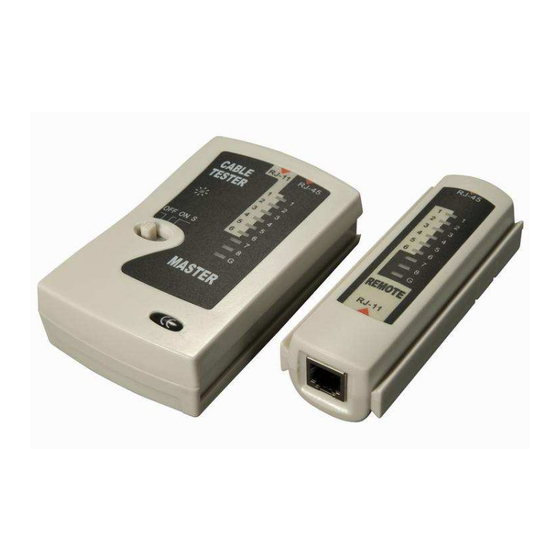
Cable Tester RJ45/12/11/10
User Manual
Benutzerhandbuch
Manuel Utilisateur
Manuale d'uso
LINDY No. 43059, 43057
www.LINDY.com
For Home and Office Use
Tested to Comply with FCC Standards
© LINDY ELECTRONICS LIMITED & LINDY-ELEKTRONIK GMBH - FIRST EDITION (MAY 2010)
English Manual
Introduction
Thank you for purchasing the LINDY RJ-45/-12/-11/-10 cable tester.
With this tester you can test UTP and STP and telephone cables with the
above mentioned connectors. It can be used to read and check the pin-
out configuration of cables before and after installation. A separate
passive remote module is included for remote testing of pre-installed
cables.
For operation, this tester requires a 9V DC block battery (not included). It
is also compatible with rechargeable 9V DC batteries. Open the battery
English
compartment and install the battery before use.
Deutsch
Package Contents
Français
Italiano
1x Cable Tester (Main and Remote unit)
This User Manual
Operation
Do NOT use this tester on cables that are connected to any
network or any other active CATV components. Disconnect
both ends of the cable to be tested from existing installation
before connecting it to the cable tester!
•
•
The cable tester has two receptacles on each unit, one labeled RJ-45
and one labeled RJ-11.
•
Use the RJ-45 receptacles to test RJ-45 and RJ-10 cable and use the
RJ-11 receptacles to test RJ-12 and RJ-11 cables.
RJ-10 cables are often used in telecommunications. You can find them
on most telephones, connecting the handset to the main unit. The RJ-10
connector is much smaller than the RJ-45 but it fits into the tester's RJ-45
receptacle which allows proper testing.
RJ-11 and RJ-12 cables use the same connectors. RJ-12 cables, also
known as 6P6C cables, have all 6 pins connected while RJ-11 cables
also known as 6P4C only have the 4 center pins connected.
Connect both cable ends to the appropriate connectors on the main and
remote unit and switch on the tester. The switch has 3 positions: OFF /
ON / S = Slow. The pin-out of the cable is auto-scanned from pin 1 to pin
8 and then ground. For a 1:1 connected cable, the LEDS of the main and
remote unit should blink in unison. If the LEDs blink in different order then
the cable may be of a Cross Over type. If an LED only lights up on the
main but not on the remote unit the connection may be damaged (open).
For RJ-45 STP cables, all LEDs should light up in sequence from 1 to 8
and then G G G G round. For UTP cables, G G G G round is not available.
For RJ-12 cables, LEDs 1 to 6 should light up in sequence.
For RJ-11 and RJ-10 cables, LEDs 3 to 6 should light up in sequence.
•
Deutsches Benutzerhandbuch
Übersicht
Mit diesem Kabeltester können Sie ungeschirmte UTP und geschirmte
STP Kabel mit RJ45/12/11/10 Steckern testen. Er prüft und zeigt die
Kabelkonfiguration bzw. das Pinout an und kann sowohl für kurze
unverlegte Kabel sowie für bereits verlegte lange Kabelsegmente
verwendet werden. Die seitlich befestigte passive Remoteeinheit kann
abgezogen und am anderen Ende der Verlegestrecke angebracht
werden.
Der
Tester
benötigt
eine
9V
DC
entsprechenden Akku, der nicht im Lieferumfang enthalten ist. Öffnen Sie
das Batteriefach und schließen Sie die Batterie dort an.
Lieferumfang
1x Kabeltester (Haupt- und Remoteeinheit)
Dies Handbuch
Verwendung
Verwenden Sie diesen Tester NICHT an irgendwelchen
Kabeln die noch mit Netzwerkgeräten oder anderen aktiven
CATV Geräten verbunden sind! Ziehen Sie beide Enden der
zu testenden Kabel ab BEVOR Sie den Tester anschließen!
An jeder Einheit des Testers befinden sich zwei Buchsen, eine mit RJ45
und eine mit RJ11 bezeichnet. Verwenden Sie die RJ45 Buchsen zum
Testen von RJ45 und RJ10 Kabeln, und die RJ11 Buchsen für RJ11 und
RJ12 Kabel.
RJ10 Kabel werden häufig in der Telekommunikation verwendet. Sie
finden Sie an den meisten Telefonen als Kabel zwischen dem Hörer und
dem Telefon. Der RJ10 Stecker ist zwar viel kleiner als der RJ45
Stecker, dennoch kann der RJ10 Stecker problemlos in die RJ45 Buchse
gesteckt werden. RJ11 und RJ12 Kabel verwenden den gleichen
Stecker. RJ12 Kabel, auch als 6P6C bezeichnet, haben alle 6
Anschlüsse verbunden, während RJ11 Kabel, auch 6P4C,
mittleren 4 Anschlüsse verbunden haben.
Schließen Sie zum Testen beide Kabelenden an die zugehörigen
Buchsen an und schalten Sie den Tester ein. Der Schalter hat 3
Positionen: OFF=AUS / ON=AN / S= Langsam (Slow). Das Pinout wird
automatisch gescannt von Pin 1 bis Pin 8 und
Ungeschirmte Kabel haben keine G G G G round-Verbindung. Bei 1:1
verbundenen Kabeln sollten die LEDs in paralleler Reihenfolge
an Haupt- und Remoteeinheit aufleuchten. Wenn sie in
unterschiedlicher Reihenfolge aufleuchten hat das Kabel ein
Cross Over Pinout oder einen Fehler. Wenn die LED nur an der
Haupteinheit leuchtet ist dieser Pin des Kabels nicht verbunden.
Für RJ45 STP 1:1 Kabel müssen alle LEDs 1-8 und dann G für die
Anschirmung der Reihe nach leuchten, bei UTP / ungeschirmten Kabeln
darf G nicht leuchten.
Für RJ11 Kabel müssen die LEDs 1-6 der Reihe nach leuchten,
für RJ11 und RJ10 Kabel nur die LEDs 3-6 .
Blockbatterie
bzw.
einen
nur die
G G G G round (Abschirmung).
Advertisement

Related Manuals for Lindy RJ45

Summary of Contents for Lindy RJ45
- Page 1 For RJ-12 cables, LEDs 1 to 6 should light up in sequence. Für RJ45 STP 1:1 Kabel müssen alle LEDs 1-8 und dann G für die For RJ-11 and RJ-10 cables, LEDs 3 to 6 should light up in sequence.
- Page 2 Per i cavi RJ-45 STP tutti i LED dovrebbero accendersi in sequenza da 1 Pour les câbles RJ45 STP 1:1, toutes les LEDs 1-8 puis G pour la masse a 8 e quindi la massa (G G G G round). Per i cavi UTP la massa non è presente.
Need help?
Do you have a question about the RJ45 and is the answer not in the manual?
Questions and answers