Table of Contents
Advertisement
Quick Links
Advertisement
Table of Contents

Related Manuals for Super Superserver 5038ML-H24TRF

Summary of Contents for Super Superserver 5038ML-H24TRF
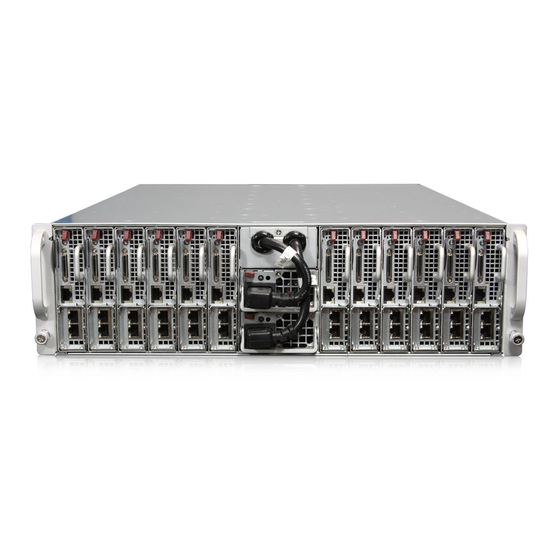
- Page 1 UPER ® UPER ERVER MicroCloud 5038ML-H24TRF USER’S MANUAL Revision 1.0...
- Page 2 Clara County in the State of California, USA. The State of California, County of Santa Clara shall be the exclusive venue for the resolution of any such disputes. Super Micro's total liability for all claims will not exceed the price paid for the hardware product.
-
Page 3: About This Manual
About This Manual This manual is written for professional system integrators and PC technicians. It pro- vides information for the installation and use of the SuperServer 5038ML-H24TRF. Installation and maintenance should be performed by experienced technicians only. The SuperServer 5038ML-H24TRF is a 24-node, MicroCloud server system based on the SC939HD-R2K02B 3U chassis and 12 X10SLE-DF motherboards. - Page 4 UPER ERVER 5038ML-H24TRF User's Manual Chapter 5: Advanced Motherboard Setup Chapter 5 provides detailed information on the X10SLE-DF motherboard, including the locations and functions of connectors, headers and jumpers. Refer to this chap- ter when adding or removing processors or main memory and when reconfi guring the motherboard.
- Page 5 Preface Notes...
-
Page 6: Table Of Contents
UPER ERVER 5038ML-H24TRF User's Manual Table of Contents Chapter 1 Introduction Overview ......................1-1 Motherboard Features ..................1-2 Processors ...................... 1-2 Memory ......................1-2 SATA ........................ 1-2 Rear I/O Ports ....................1-2 IPMI ......................... 1-2 Server Chassis Features ................1-4 System Power .................... - Page 7 Table of Contents Chapter 4 Standardized Warning Statements for AC Systems About Standardized Warning Statements ............4-1 Warning Defi nition ................... 4-1 Installation Instructions ..................4-4 Circuit Breaker ....................4-5 Power Disconnection Warning ................ 4-6 Equipment Installation ..................4-8 Restricted Area ....................4-9 Battery Handling ....................
- Page 8 UPER ERVER 5038ML-H24TRF User's Manual SuperDoctor® 5 .................... 5-17 5-13 Onboard Battery .................... 5-18 Chapter 6 Advanced Chassis Setup Static-Sensitive Devices .................. 6-1 Precautions ..................... 6-1 Removing the Chassis Cover ................. 6-2 Corresponding Sleds and Fans ..............6-3 Removing and Installing Sleds ............... 6-4 Installing/Removing Hard Drives ..............
-
Page 9: Chapter 1 Introduction
Chapter 1 Introduction Overview The SuperServer 5038ML-H24TRF is a 24 node, MicroCloud server system com- prised of the SC939HD-R2K02B 3U chassis and 12 X10SLE-DF motherboards. Please refer to our web site for information on operating systems that have been certifi ed for use with the 5038ML-H24TRF (www.supermicro.com). -
Page 10: Motherboard Features
UPER ERVER 5038ML-H24TRF User's Manual Motherboard Features The 5038ML-H24TRF includes a total of 12 X10SLE-DF single processor mother- boards, which are based on the Intel C224 PCH chipset. Each motherboard consti- tutes two nodes in the system by supporting two independent CPUs. Below are the main features of the X10SLE-DF. -
Page 11: System Block Diagram
Chapter 1: Introduction Figure 1-1. Intel C224 Chipset: System Block Diagram Note: This is a general block diagram. See Chapter 5 for details. SVID SVID VRM 12.5 MISC VRs MISC VRs VRM 12.5 DDR3 (CHA) DIMM1 DDR3 (CHA) DIMM1 DIMM2(Far) 1600/1333MHz Haswell Haswell... -
Page 12: Server Chassis Features
UPER ERVER 5038ML-H24TRF User's Manual Server Chassis Features The following is a general outline of the main features of the SC939HD-R2K02B server chassis. System Power The SC939HD-R2K02B features a redundant 2000W high-effi ciency power supply comprised of two separate power modules. This power redundancy feature allows you to replace a failed power supply without shutting down the system. -
Page 13: Contacting Supermicro
Chapter 1: Introduction Contacting Supermicro Headquarters Address: Super Micro Computer, Inc. 980 Rock Ave. San Jose, CA 95131 U.S.A. Tel: +1 (408) 503-8000 Fax: +1 (408) 503-8008 Email: marketing@supermicro.com (General Information) support@supermicro.com (Technical Support) Web Site: www.supermicro.com Europe Address: Super Micro Computer B.V. - Page 14 UPER ERVER 5038ML-H24TRF User's Manual Notes...
-
Page 15: Chapter 2 Server Installation
Chapter 2: Server Installation Chapter 2 Server Installation Overview This chapter outlines the procedure to set up your system and install it to a rack. If your system is not already fully integrated with a motherboard, processors, system memory etc., please turn to the chapter or section noted in each step for details on installing specifi... -
Page 16: Warnings And Precautions
UPER ERVER 5038ML-H24TRF User's Manual • This product is not suitable for use with visual display work place devices acccording to §2 of the the German Ordinance for Work with Visual Display Units. Warnings and Precautions Rack Precautions • Ensure that the leveling jacks on the bottom of the rack are fully extended to the fl... -
Page 17: Rack Mounting Considerations
Chapter 2: Server Installation Rack Mounting Considerations Ambient Operating Temperature If installed in a closed or multi-unit rack assembly, the ambient operating tempera- ture of the rack environment may be greater than the ambient temperature of the room. Therefore, consideration should be given to installing the equipment in an environment compatible with the manufacturer’s maximum rated ambient tempera- ture (Tmra). -
Page 18: Installing The System Into A Rack
UPER ERVER 5038ML-H24TRF User's Manual Installing the System into a Rack Use the procedure below for installing the system to a rack. 1. Decide where you want to place the system into the rack (see "Rack Mount- ing Considerations" in the previous section). 2. - Page 19 Chapter 2: Server Installation Figure 2-2. Securing the Rails to the Rack Note: These handles are optional and need only be installed when mounting the system into a short rack. When mounting into a deep rack, they are unnecessary and regular screws should be used instead of thumbscrews. 6.
- Page 20 UPER ERVER 5038ML-H24TRF User's Manual Figure 2-3. Installing to the Rack Note: this fi gure is for illustrative purposes only. Always install servers to the bot- tom of a rack fi rst. Stability hazard. The rack stabilizing mechanism must be in place, or the rack must be bolted to the fl...
-
Page 21: Chapter 3 System Interface
Chapter 3: System Interface Chapter 3 System Interface Overview LEDs are included on the serverboard nodes and the power supply modules to keep you informed of their operational status. This chapter explains the meanings of all LED indicators and the appropriate response you may need to take. Nodes Power Button/LED The main power button on each of the nodes functions as an on/off switch and is... -
Page 22: Uid Led
UPER ERVER 5038ML-H24TRF User's Manual UID LED A Unit Identifi er LED can be found beside the power button/LED. See the table below for the LED indications. LED Appearance Description Solid Blue UID activated KVM Switch LED There is also an LED built into the KVM switch. This LED is ised to indicate which node is being employed for KVM, green for node 1 or amber for node 2. - Page 23 Chapter 3: System Interface Figure 3-1. Node View UID LED Warning LED Node 1 Power LED Node 2 Power LED KVM Switch LED Node 1 LAN Ports Node 2 LAN Ports...
- Page 24 UPER ERVER 5038ML-H24TRF User's Manual Notes...
-
Page 25: Chapter 4 Standardized Warning Statements For Ac Systems
Chapter 4: Warning Statements for AC Systems Chapter 4 Standardized Warning Statements for AC Systems About Standardized Warning Statements The following statements are industry standard warnings, provided to warn the user of situations which have the potential for bodily injury. Should you have questions or experience difficulty, contact Supermicro's Technical Support department for assistance. - Page 26 UPER ERVER 5038ML-H24TRF User's Manual Warnung WICHTIGE SICHERHEITSHINWEISE Dieses Warnsymbol bedeutet Gefahr. Sie befi nden sich in einer Situation, die zu Verletzungen führen kann. Machen Sie sich vor der Arbeit mit Geräten mit den Gefahren elektrischer Schaltungen und den üblichen Verfahren zur Vorbeugung vor Unfällen vertraut.
- Page 27 Warning Statements for AC Systems ﺟﺴﺪﻳﺔ ﺍﺻﺎﺑﺔ ﺗﺘﺴﺒﺐ ﻓﻲ ﺣﺎﻟﺔ ﻳﻤﻜﻦ ﺃﻥ ﺍﻧﻚ ﻓﻲ ﺧﻄﺮ ﻳﻌﻨﻲ ﻫﺬﺍ ﺍﻟﺮﻣﺰ !ﺗﺤﺬﻳﺮ ﺍﻟﺪﻭﺍﺋﺮ ﺑﺎﻟﻤﺨﺎﻁﺮ ﺍﻟﻨﺎﺟﻤﺔ ﻋﻦ ﻦ ﻋﻠﻰ ﻋﻠﻢ ، ﻛ ﻣﻌﺪﺍﺕ ﺗﻌﻤﻞ ﻋﻠﻰ ﺃﻱ ﻗﺒﻞ ﺃﻥ ﺍﻟﻜﻬﺮﺑﺎﺋﻴﺔ ﺣﻮﺍﺩﺙ ﺃﻱ ﻭﻗﻮﻉ ﻤﻨﻊ ﻟ ﺍﻟﻮﻗﺎﺋﻴﺔ...
-
Page 28: Installation Instructions
UPER ERVER 5038ML-H24TRF User's Manual Installation Instructions Warning! Read the installation instructions before connecting the system to the power source. 警告 将此系统连接电源前,请先阅读安装说明。 警告 將系統與電源連接前,請先閱讀安裝說明。 Warnung Vor dem Anschließen des Systems an die Stromquelle die Installationsanweisungen lesen. ¡Advertencia! Lea las instrucciones de instalación antes de conectar el sistema a la red de alimentación. -
Page 29: Circuit Breaker
Chapter 4: Warning Statements for AC Systems Circuit Breaker Warning! This product relies on the building's installation for short-circuit (overcurrent) protection. Ensure that the protective device is rated not greater than: 250 V, 20 A. 警告 此产品的短路(过载电流)保护由建筑物的供电系统提供,确保短路保护设备的额定电 流不大于250V,20A。 警告 此產品的短路(過載電流)保護由建築物的供電系統提供,確保短路保護設備的額定電 流不大於250V,20A。... -
Page 30: Power Disconnection Warning
UPER ERVER 5038ML-H24TRF User's Manual Waarschuwing Dit product is afhankelijk van de kortsluitbeveiliging (overspanning) van uw electrische installatie. Controleer of het beveiligde aparaat niet groter gedimensioneerd is dan 220V, 20A. Power Disconnection Warning Warning! The system must be disconnected from all sources of power and the power cord removed from the power supply module(s) before accessing the chassis interior to install or remove system components. - Page 31 Chapter 4: Warning Statements for AC Systems ¡Advertencia! El sistema debe ser disconnected de todas las fuentes de energía y del cable eléctrico quitado de los módulos de fuente de alimentación antes de tener acceso el interior del chasis para instalar o para quitar componentes de sistema. Attention Le système doit être débranché...
-
Page 32: Equipment Installation
UPER ERVER 5038ML-H24TRF User's Manual Equipment Installation Warning! Only trained and qualifi ed personnel should be allowed to install, replace, or service this equipment. 警告 只有经过培训且具有资格的人员才能进行此设备的安装、更换和维修。 警告 只有經過受訓且具資格人員才可安裝、更換與維修此設備。 Warnung Das Installieren, Ersetzen oder Bedienen dieser Ausrüstung sollte nur geschultem, qualifi ziertem Personal gestattet werden. ¡Advertencia! Solamente el personal califi... -
Page 33: Restricted Area
Chapter 4: Warning Statements for AC Systems Waarschuwing Deze apparatuur mag alleen worden geïnstalleerd, vervangen of hersteld door geschoold en gekwalifi ceerd personeel. Restricted Area Warning! This unit is intended for installation in restricted access areas. A restricted access area can be accessed only through the use of a special tool, lock and key, or other means of security. -
Page 34: Battery Handling
UPER ERVER 5038ML-H24TRF User's Manual אזור עם גישה מוגבלת !אזהרה יש להתקין את היחידה באזורים שיש בהם הגבלת גישה. הגישה ניתנת בעזרת .('כלי אבטחה בלבד )מפתח, מנעול וכד ﻣﺤﻈﻮﺭﺓ ﻣﻨﺎﻁﻖ ﻟﺘﺮﻛﻴﺒﻬﺎ ﻓﻲ ﻫﺬﻩ ﺍﻟﻮﺣﺪﺓ ﺗﺨﺼﻴﺺ ﺗﻢ ،ﺃﺩﺍﺓ ﺧﺎﺻﺔ ﻣﻦ ﺧﻼﻝ ﺍﺳﺘﺨﺪﺍﻡ ﻓﻘﻂ... - Page 35 Chapter 4: Warning Statements for AC Systems Warnung Bei Einsetzen einer falschen Batterie besteht Explosionsgefahr. Ersetzen Sie die Batterie nur durch den gleichen oder vom Hersteller empfohlenen Batterietyp. Entsorgen Sie die benutzten Batterien nach den Anweisungen des Herstellers. Attention Danger d'explosion si la pile n'est pas remplacée correctement. Ne la remplacer que par une pile de type semblable ou équivalent, recommandée par le fabricant.
-
Page 36: Redundant Power Supplies
UPER ERVER 5038ML-H24TRF User's Manual Redundant Power Supplies Warning! This unit might have more than one power supply connection. All connections must be removed to de-energize the unit. 警告 此部件连接的电源可能不止一个,必须将所有电源断开才能停止给该部件供电。 警告 此裝置連接的電源可能不只一個,必須切斷所有電源才能停止對該裝置的供電。 Warnung Dieses Gerät kann mehr als eine Stromzufuhr haben. Um sicherzustellen, dass der Einheit kein trom zugeführt wird, müssen alle Verbindungen entfernt werden. -
Page 37: Backplane Voltage
Chapter 4: Warning Statements for AC Systems ﺍﻣﺪﺍﺩ ﺍﻟﻄﺎﻗﺔ ﺑﻮﺣﺪﺍﺕ ﻋﺪﺓ ﺍﺗﺼﺎﻻﺕ ﺠﻬﺎﺯ ﺍﻟ ﻳﻜﻮﻥ ﻟﻬﺬﺍ ﻗﺪ ﺍﻟﻜﻬﺮﺑﺎء ﻋﻦ ﻮﺣﺪﺓ ﺍﻟ ﻟﻌﺰﻝ ﻛﺎﻓﺔ ﺍﻻﺗﺼﺎﻻﺕ ﻳﺠﺐ ﺇﺯﺍﻟﺔ Waarschuwing Deze eenheid kan meer dan één stroomtoevoeraansluiting bevatten. Alle aansluitingen dienen verwijderd te worden om het apparaat stroomloos te maken. Backplane Voltage Warning! Hazardous voltage or energy is present on the backplane when the system is... -
Page 38: Comply With Local And National Electrical Codes
UPER ERVER 5038ML-H24TRF User's Manual מתח בפנל האחורי !הרה אז קיימת סכנת מתח בפנל האחורי בזמן תפעול המערכת. יש להיזהר במהלך .העבודה ﺍﻟﻠﻮﺣﺔ ﺃﻭﺍﻟﻄﺎﻗﺔ ﺍﻟﻤﻮﺟﻮﺩﺓ ﻋﻠﻰ ﺍﻟﺘﻴﺎﺭ ﺍﻟﻜﻬﺮﺑﺎﺋﻲ ﻣﻦ ﺧﻄﺮ ﻫﻨﺎﻙ ﻫﺬﺍ ﺍﻟﺠﻬﺎﺯ ﺧﺪﻣﺔ ﻛﻦ ﺣﺬﺭﺍ ﻋﻨﺪ ﻳﻌﻤﻞ ﺍﻟﻨﻈﺎﻡ ﻋﻨﺪﻣﺎ ﻳﻜﻮﻥ Waarschuwing Een gevaarlijke spanning of energie is aanwezig op de backplane wanneer het systeem in gebruik is. -
Page 39: Product Disposal
Chapter 4: Warning Statements for AC Systems Attention L'équipement doit être installé conformément aux normes électriques nationales et locales. תיאום חוקי החשמל הארצי !אזהרה הציוד חייבת להיות תואמת לחוקי החשמל המקומיים והארציים התקנת ﺍﻟﻤﺘﻌﻠﻘﺔ ﺍﻟﻤﺤﻠﻴﺔ ﻭﺍﻟﻮﻁﻨﻴﺔ ﻘﻮﺍﻧﻴﻦ ﻳﺠﺐ ﺃﻥ ﻳﻤﺘﺜﻞ ﻟﻠ ﺍﻟﻜﻬﺮﺑﺎﺋﻴﺔ... -
Page 40: Hot Swap Fan Warning
UPER ERVER 5038ML-H24TRF User's Manual ¡Advertencia! Al deshacerse por completo de este producto debe seguir todas las leyes y reglamentos nacionales. Attention La mise au rebut ou le recyclage de ce produit sont généralement soumis à des lois et/ou directives de respect de l'environnement. Renseignez-vous auprès de l'organisme compétent. - Page 41 Chapter 4: Warning Statements for AC Systems 警告 當您從機架移除風扇裝置,風扇可能仍在轉動。小心不要將手指、螺絲起子和其他 物品太靠近風扇。 Warnung Die Lüfter drehen sich u. U. noch, wenn die Lüfterbaugruppe aus dem Chassis genommen wird. Halten Sie Finger, Schraubendreher und andere Gegenstände von den Öffnungen des Lüftergehäuses entfernt. ¡Advertencia! Los ventiladores podran dar vuelta cuando usted quite ell montaje del ventilador del chasis.
-
Page 42: Power Cable And Ac Adapter
UPER ERVER 5038ML-H24TRF User's Manual Power Cable and AC Adapter Warning! When installing the product, use the provided or designated connection cables, power cables and AC adaptors. Using any other cables and adaptors could cause a malfunction or a fi re. Electrical Appliance and Material Safety Law prohibits the use of UL or CSA -certifi... - Page 43 Chapter 4: Warning Statements for AC Systems Attention Lors de l'installation du produit, utilisez les bables de connection fournis ou désigné. L'utilisation d'autres cables et adaptateurs peut provoquer un dysfonctionnement ou un incendie. Appareils électroménagers et de loi sur la sécurité Matériel interdit l'utilisation de UL ou CSA câbles certifi...
- Page 44 UPER ERVER 5038ML-H24TRF User's Manual Notes 4-20...
-
Page 45: Chapter 5 Advanced Motherboard Setup
Chapter 5: Advanced Motherboard Setup Chapter 5 Advanced Motherboard Setup This chapter covers the steps required to connect the data and power cables and install add-on cards. All motherboard jumpers and connections are also described. A layout and quick reference chart are included in this chapter for your reference. Remember to completely close the chassis when you have fi... -
Page 46: Motherboard Installation/Removal
UPER ERVER 5038ML-H24TRF User's Manual Motherboard Installation/Removal The motherboards are mounted on sleds to simplify installing and removing them from the chassis. If a failed motherboard needs to be returned for repair or replace- ment, it is to be shipped mounted in its sled and not by itself. See Chapter 6 for instructions on installing and removing the sleds from the chassis. -
Page 47: Processor And Heatsink Installation
Chapter 5: Advanced Motherboard Setup Processor and Heatsink Installation Warning: Avoid placing direct pressure to the top of the processor. Notes: • Always connect the power cord last and always remove it before adding, re- moving or changing any hardware components. Make sure that you install the processor into the CPU socket before you install the CPU heatsink. - Page 48 UPER ERVER 5038ML-H24TRF User's Manual 3. Once the load plate is open, use your thumb and your index fi nger to hold the CPU at the north center edge and the south center edge of the CPU. North Center Edge South Center Edge 4.
- Page 49 Chapter 5: Advanced Motherboard Setup 7. Once the CPU is properly installed, use your thumb to gently push the load plat handle down to the handle lock and lock it. CPU properly installed Load Plate Handle is locked into place 8.
-
Page 50: Installing A Heatsink
UPER ERVER 5038ML-H24TRF User's Manual Installing a Heatsink 1. With the sled removed, remove the air shroud. 2. Do not apply any thermal grease to the heatsink or the CPU die; the required amount has already been applied. 3. Place the heatsink on top of the CPU so that the four mounting holes are aligned with those on the motherboard and the heatsink bracket underneath. -
Page 51: Installing Memory
Chapter 5: Advanced Motherboard Setup Installing Memory Caution: Exercise extreme care when installing or removing DIMM modules to prevent any possible damage to the DIMMs or their sockets How to Install Memory 1. Insert the desired number of DIMMs into the memory slots in the following order: DIMMA1, then DIMMB1, DIMMA2, DIMMB2. -
Page 52: Memory Population Guidelines
UPER ERVER 5038ML-H24TRF User's Manual Figure 5-4. Populating DIMM Slots Towards the CPU Channel A, Slot 1 Channel A, Slot 2 (Blue Slot) Channel B, Slot 1 Channel B, Slot 2 (Blue Slot) Towards the edge of the motherboard P1 DIMMs (for node 1) MAC CODE MAC CODE... -
Page 53: Motherboard Details
Chapter 5: Advanced Motherboard Setup Motherboard Details Figure 5-5. X10SLE-DF Layout USB0/1 NODE JKVM1 Battery IPMI_LAN Node Switch Switch Firmware Firmware CTRL Memory Memory CTRL JPV2 BAR CODE X10SLE-DF Rev. 1.01 CPU2 JBT2 JBT1 CPU1 JPV1... -
Page 54: X10Sle-Df Quick Reference
UPER ERVER 5038ML-H24TRF User's Manual X10SLE-DF Quick Reference Jumper Description Default Thermal Throttling Triggered by Pins 1-2 (Enabled) Power Fail Enable/Disable CMOS Clear for Node 1 (JBT1)/ JBT1/JBT2 See Section 5-9 Node 2 (JBT2) P1-JPG1/ VGA Enable/Disable for Node 1 Pins 1-2 (Enabled) P2-JPG1 (P1-JPG1)/Node 2 (P2-JPG1) -
Page 55: Connector Defi Nitions
Chapter 5: Advanced Motherboard Setup Connector Defi nitions SMC-Proprietary Add-On Card Slot An SMC-proprietary add-on card slot is located at J8 on the motherboard. Install an appropriate add-on card into this slot to provide power supply and SIG SATA interface support to Node 1 or Node 2. Press the power button located at SW1 to switch power/SIG SATA interface support between Node 1 and Node 2. -
Page 56: Jumper Settings
UPER ERVER 5038ML-H24TRF User's Manual Power Switch//LED Indicator A power switch/LED (SW1) is located next to the USB/KVM connector on the backplane of the motherboard. Use this switch to switch power for use of Node 1 or Node 2. Node Switch/KVM/LED Indicator A Node ID Switch/KVM/LED indicator (SW2) is located next to the IPMI LAN port on the backplane of the motherboard. - Page 57 Chapter 5: Advanced Motherboard Setup VGA Enable/Disable Jumpers P1-JPG1/P2-JPG1 allow the user VGA Enable/Disable Jumper Settings to enable the onboard VGA support for Jumper Setting Defi nition Node 1 (P1-JPG1) or Node 2 (P2-JPG1). Pins 1-2 Enabled The default setting is 1-2 to enable VGA Pins 2-3 Disabled support.
-
Page 58: 5-10 Onboard Indicators
UPER ERVER 5038ML-H24TRF User's Manual Thermal Throttling Triggered by Thermal Throttling by Power-Failure Power-Failure Enable Jumper Settings Jumper Setting Defi nition Close pins 1-2 of J7 to trigger Thermal Pins 1-2 Thermal Throttling Triggered Throttling when the power supply fails. (Default) See the table on the right for jumper Pins 2-3... -
Page 59: 5-11 Sata Ports
Chapter 5: Advanced Motherboard Setup Heartbeat LED Indicators Heartbeat LED Two Heartbeat LED Indicators (LE5/ LE6) are provided on the motherboard. Color/State Defi nition When LE5 is blinking, node 1 IPMI is Green: Blinking LE5: Node 1: Normal functioning normally. When LE6 is blink- Green: Blinking LE6: Node 2: ing, node 2 IPMI is functioning normally. -
Page 60: 5-12 Installing Software
UPER ERVER 5038ML-H24TRF User's Manual 5-12 Installing Software The Supermicro ftp site contains drivers and utilities for your system at ftp://ftp. supermicro.com. Some of these must be installed, such as the chipset driver. After accessing the ftp site, go into the CDR_Images directory and locate the ISO fi... -
Page 61: Superdoctor® 5
Chapter 5: Advanced Motherboard Setup SuperDoctor® 5 The Supermicro SuperDoctor 5 is a program that functions in a command-line or web-based interface in Windows and Linux operating systems. The program moni- tors system health information such as CPU temperature, system voltages, system power consumption, fan speed, and provides alerts via email or Simple Network Management Protocol (SNMP). -
Page 62: 5-13 Onboard Battery
UPER ERVER 5038ML-H24TRF User's Manual 5-13 Onboard Battery Please handle used batteries carefully. Do not damage the battery in any way; a damaged battery may release hazardous materials into the environment. Do not discard a used battery in the garbage or a public landfi ll. Please comply with the regulations set up by your local hazardous waste management agency to dispose of your used battery properly. -
Page 63: Chapter 6 Advanced Chassis Setup
Chapter 6: Advanced Chassis Setup Chapter 6 Advanced Chassis Setup This chapter covers the steps required to install components and perform main- tenance on the SC939HD-R2K02B chassis. For component installation, follow the steps in the order given to eliminate the most common problems encountered. If some steps are unnecessary, skip ahead to the step that follows. -
Page 64: Removing The Chassis Cover
UPER ERVER 5038ML-H24TRF User's Manual Removing the Chassis Cover Figure 6-1. Removing the Chassis Cover Removing the Chassis Cover 1. Disconnect the chassis from any power source. 2. Remove the six screws that secure the top rear cover to the chassis as il- lustrated above. -
Page 65: Corresponding Sleds And Fans
Chapter 6: Advanced Chassis Setup Corresponding Sleds and Fans The 5038ML-H24TRF contains 24 individual nodes contained in 12 separate motherboards mounted on sleds. Three sleds each share a common fan (see fi gure below). Figure 6-2. Corresponding Sleds and Fans Cooling Zone 1 Fan 1 Fan 2... -
Page 66: Removing And Installing Sleds
UPER ERVER 5038ML-H24TRF User's Manual Removing and Installing Sleds Release Tab Handle Figure 6-3. Removing/Installing a Sled The system features twelve removable sleds. Each sled contains an individual motherboard and hard drives. The sleds allow the motherboards/nodes to easily be installed and removed from the chassis. Removing Sleds from the System 1. -
Page 67: Installing/Removing Hard Drives
Chapter 6: Advanced Chassis Setup Installing/Removing Hard Drives The hard drives are installed directly to the sled, which must fi rst be removed from the system. For this reason, hard drives are not hot-swappable. Either two 2.5" hard drives or four 2.5" slim SSD drives can be installed in each sled (node). An optional kit is required to install four 2.5"... - Page 68 UPER ERVER 5038ML-H24TRF User's Manual Installing/Removing SSDs from the Sled 1. Remove the sled from the chassis by following the procedure in the previous section. 2. Place the sled on a fl at, non-conductive surface. 3. Insert two SSD drives with the printed circuit board side facing downward so that the mounting holes in the drive align with those in the bottom of the sled.
-
Page 69: System Fans
Chapter 6: Advanced Chassis Setup System Fans Four 9-cm fans circulate air through the chassis to lower the internal temperature. These fans are designed to be easily changed, with no tools required and no need to remove any other parts inside the chassis. In the event of a fan failure, follow the instructions below to replace it. -
Page 70: Power Supply
UPER ERVER 5038ML-H24TRF User's Manual Power Supply The system includes a redundant 2000 watt, high-effi ciency power supply. The two power supply modules are auto-switching capable, which enables them to automatically sense and operate at a 100V to 240V input voltage. An amber light is illuminated on the power supply when the power is off. -
Page 71: Power Supply Replacement
Chapter 6: Advanced Chassis Setup Power Supply Replacement In the event that one of the power supplies needs to be replaced, one power supply can be removed without powering-down the system. Replacement power supply units may be ordered directly from Supermicro. Note that the power supply on top is PSU1 and the power supply on the bottom is PSU2. - Page 72 UPER ERVER 5038ML-H24TRF User's Manual Changing the PSU2 Power Supply Module 1. With the system running, unplug the AC power cord from the PSU2 power supply module. 2. Push and hold the release tab on the back of the power supply. 3.
-
Page 73: Chapter 7 Bios
Chapter 7: BIOS Chapter 7 BIOS Introduction This chapter describes the AMI BIOS Setup Utility for the X10SLE-DF. The ROM BIOS is stored in a Flash EEPROM and can be easily updated. This chapter de- scribes the basic navigation of the AMI BIOS setup utility setup screens. Note: For AMI BIOS recovery, please refer to the UEFI BIOS Recovery Instructions in Appendix C. -
Page 74: How To Start The Setup Utility
UPER ERVER 5038ML-H24TRF User's Manual How to Start the Setup Utility Normally, the only visible Power-On Self-Test (POST) routine is the memory test. As the memory is being tested, press the <Delete> key to enter the main menu of the AMI BIOS setup utility. From the main menu, you can access the other setup screens. - Page 75 Chapter 7: BIOS System Date/System Time Use this option to change the system date and time. Highlight System Date or Sys- tem Time using the arrow keys. Enter new values through the keyboard. Press the <Tab> key or the arrow keys to move between fi elds. The date must be entered in the Day MM/DD/YY format.
-
Page 76: Advanced Setup Confi Gurations
UPER ERVER 5038ML-H24TRF User's Manual Advanced Setup Confi gurations Use the arrow keys to select Boot Setup and press <Enter> to access the submenu items. Warning: Take caution when changing the Advanced settings. An incorrect value, an excessively high DRAM frequency, or an improper DRAM timing setting may make the system unstable. - Page 77 Chapter 7: BIOS Wait For 'F1' If Error Select Enabled to force the system to wait until the 'F1' key is pressed if an error occurs. The options are Disabled and Enabled. Interrupt 19 Capture Interrupt 19 is the software interrupt that handles the boot disk function. When this item is set to Enabled, the BIOS ROM of the host adaptors will "capture"...
- Page 78 UPER ERVER 5038ML-H24TRF User's Manual • FSB Speed • Maximum CPU Speed • Minimum CPU Speed • CPU Speed • Processor Cores • Intel HT(Hyper-Threading) Technology • Intel VT-x (Virtualization) Technology • Intel SMX (Safer Mode Extensions) Technology • 64-bit •...
- Page 79 Chapter 7: BIOS Active Processor Cores This feature determines how many CPU cores will be activated for each CPU. When all is selected, all cores in the CPU will be activated. (Please refer to Intel's web site for more information.) The options are All, 1, 2, and 3. Limit CPUID Maximum Select Enabled to set the maximum CPU ID value and to boot the legacy operat- ing systems that cannot support processors with extended CPUID functions.
- Page 80 UPER ERVER 5038ML-H24TRF User's Manual turbo mode for the CPU. The options are Max Non-Turbo Performance and Turbo Performance. EIST EIST (Enhanced Intel SpeedStep Technology) allows the system to automatically adjust processor voltage and core frequency in an effort to reduce power consump- tion and heat dissipation.
- Page 81 Chapter 7: BIOS CPU Power Limit3 Duty Cycle Use this feature to set the value of CPU Power Limit3 Duty Cycle for your system. Use the number keys on your keyboard to enter the value. Enter 0 to use the manufacturer's default setting.
- Page 82 UPER ERVER 5038ML-H24TRF User's Manual ment via IPMI 2.0. The options are Performance, Balanced Performance, Balanced Energy, and Energy Effi cient. VR Current Value Use this feature to set the limit on the current voltage regulator. Press "+" or "-" on your keyboard to change this value.
- Page 83 Chapter 7: BIOS C1 State Auto Demotion When this item is enabled, the CPU will conditionally demote C3, C6, or C7 requests to C1 based on the un-cored auto-demote state. The options are Disabled and Enabled. C3 State Auto Demotion When this item is enabled, the CPU will conditionally demote C6 or C7 requests to C3 based on the un-cored auto-demote state.
- Page 84 UPER ERVER 5038ML-H24TRF User's Manual PCIe Confi guration This item displays the information of the (graphics) device installed in a PCI-E slot. Run-time C7 Allowed Select Enabled for Run-time C7 support, which will allow the CPU to enter the deep-sleep state while the system is in operation to reduce power consumption.
- Page 85 Chapter 7: BIOS • P1-DIMMA1 • P1-DIMMA2 • P1-DIMMB1 • P1-DIMMB2 • CAS Latency (tCL) • Minimum Delay Time • CAS to RAS (tRODmin) • Row Precharge (tRPmin) • Active to Precharege (tRASmin) Memory Frequency Limiter Use this feature to set the limit of memory frequency for DIMM modules installed on the motherboard.
- Page 86 UPER ERVER 5038ML-H24TRF User's Manual PCH-IO Confi guration This item displays the information for the PCH-IO Chip. • Intel PCH Rev ID • USB Confi guration • USB Devices EHCI1 Select Enabled to enable EHCI (Enhanced Host Controller Interface) Controller 1 for USB 2.0 support.
- Page 87 Chapter 7: BIOS XHCI Mode This feature handles the operation mode for the XHCI (Extensible Host Control- ler Interface) controller. The settings are Smart Auto, Auto, Enabled, Disabled, and Manual. SATA Confi guration When this submenu is selected, the AMI BIOS automatically detects the presence of the SATA Devices and displays the following items: SATA Controllers This item Enables or Disables the built-in SATA controllers on the motherboard.
- Page 88 UPER ERVER 5038ML-H24TRF User's Manual Port 0 ~ Port 1 Spin Up Device On an edge detect from 0 to 1, set this item to allow the PCH to start a COMRE- SET initialization sequence to the device. The options are Enabled and Disabled. If the item - SATA Mode Select is set to IDE, the following items are displayed: Serial ATA Port 0~ Port 1 This item displays the information detected on the installed SATA drives on the...
- Page 89 Chapter 7: BIOS PCIe/PCI/PnP Confi guration This feature allows the user to set the PCI/PnP confi gurations for the following items: Above 4G Decoding Select Enabled for 64-bit devices to be decoded above the 4GB address space if 64bit PCI decoding is supported by the system. The options are Disabled and Enabled.
- Page 90 UPER ERVER 5038ML-H24TRF User's Manual IPv6 PXE Support (Available when Network Stack is set to Enabled) Set this item to Enabled to activate IPv6 PXE Support. The options are Enabled and Disabled. ACPI Settings High Precision Timer Select Enabled to activate the High Precision Timer that produces periodic interrupts at a much higher frequency than a Real-Time Clock (RTC) does in synchronizing multimedia streams, providing smooth playback and reducing dependence on other timestamp calculation devices, such as an x86 RDTSC Instruction embedded in the...
-
Page 91: Serial Port Console Redirection
Chapter 7: BIOS Super IO Confi guration Super IO Chip AST2400 Serial Port 1 Confi guration Serial Port Select Enabled to enable the onboard serial port. The options are Enabled and Disabled. Change Settings Use this feature to specify the base I/O port address and the Interrupt Request address of Serial Port 1. - Page 92 UPER ERVER 5038ML-H24TRF User's Manual Data Bits Use this feature to set the data transmission size for Console Redirection. The options are 7 Bits and 8 Bits. Parity A parity bit can be sent along with regular data bits to detect data transmission errors.
- Page 93 Chapter 7: BIOS Putty KeyPad This feature selects Function Keys and KeyPad settings for Putty, which is a terminal emulator designed for the Windows OS. The options are VT100, LINUX, XTERMR6, SC0, ESCN, and VT400. Redirection After BIOS Post Use this feature to enable or disable Legacy Console Redirection after BIOS POST (Power-On Self Test).
- Page 94 UPER ERVER 5038ML-H24TRF User's Manual Bits Per Second This item sets the transmission speed for a serial port used in Console Redirec- tion. Make sure that the same speed is used in the host computer and in the client computer. A lower transmission speed may be required for long and busy lines.
-
Page 95: Event Logs
Chapter 7: BIOS Event Logs Change SMBIOS Event Log Settings Enabling/Disabling Options SMBIOS Event Log Select Enabled to support SMBIOS Event Logging during system boot. The options are Enabled and Disabled. PCI Error Logging Support Select Enabled to support PCI Error Logging during system boot. The options are Enabled and Disabled. -
Page 96: Ipmi
UPER ERVER 5038ML-H24TRF User's Manual SMBIOS Event Long Standard Settings Log System Boot Event This feature toggles the System Boot Event logging to enabled or disabled. The options are Disabled and Enabled. MECI The Multiple-Event-Count Increment (MECI) counter counts the number of oc- curences. -
Page 97: System Event Log
Chapter 7: BIOS System Event Log Enabling/Disabling Options SEL Components Select Enabled for all system event logging at bootup. The options are Enabled and Disabled. Erasing Settings Erase SEL Select Yes, On next reset to erase all system event logs upon the next system reboot. - Page 98 UPER ERVER 5038ML-H24TRF User's Manual it to the system manually in the fi eld. If DHCP is selected, the BIOS will search for a DHCP (Dynamic Host Confi guration Protocol) server in the network that it is at- tached to and request the next available IP address for this computer. The options are DHCP and Static.
-
Page 99: Boot Settings
Chapter 7: BIOS Boot Settings Use this feature to confi gure THE boot settings: Set Boot Priority This option prioritizes the order of bootable devices that the system to boot from. Press <ENTER> on each entry from top to bottom to select devices. •... - Page 100 UPER ERVER 5038ML-H24TRF User's Manual Hard Disk Drive BBS Priorities • 1st Device • 2nd Device Network Device BBS Priorities • 1st Device UEFI Boot Drive BBS Priorities • 1st Boot Device Add New Boot Option This feature allows the user to add a boot device from which the systems will boot after power-on.
- Page 101 Chapter 7: BIOS Delete Driver Option This feature allows the user to delete a previously defi ned boot device from which the systems boots during startup. The settings are [any pre defi ned boot device]. 7-29...
-
Page 102: Security Settings
UPER ERVER 5038ML-H24TRF User's Manual Security Settings This menu allows the user to confi gure the following security settings for the system. Administrator Password Use this feature to set the Administrator password, which is required to enter the BIOS setup utility. The length of the password should be from 3 to 8 characters long. -
Page 103: Save & Exit
Chapter 7: BIOS Save & Exit Select the Save & Exit tab from the BIOS Setup Utility screen to enter the Exit BIOS Setup screen. Discard Changes and Exit Select this option to exit the BIOS Setup without making any permanent changes to the system confi... - Page 104 UPER ERVER 5038ML-H24TRF User's Manual Restore Optimized Defaults To set this feature, select Restore Defaults from the Exit menu and press <Enter>. These are factory settings designed for maximum system performance, but not for maximum stability. Save As User Defaults To set this feature, select Save as User Defaults from the Exit menu and press <Enter>.
-
Page 105: Appendix A System Specifi Cations
Appendix B: System Specifi cations Appendix A System Specifi cations Note that the sustem is composed of 12 motherboards on sleds with each mother- board making up two logical nodes in the system. Processors Each motherboard supports two Intel® Xeon® E3-1200 v3 (up to 80W) or 4th Gen Core i3, Pentium®, Celeron®... - Page 106 UPER ERVER 5038ML-H24TRF User's Manual Weight Barebone: 95 lbs. (43.2 kg) System Cooling Four 9-cm system fans System Input Requirements AC Input Voltage: 100 - 240V AC auto-range Rated Input Current: 11.5 - 5.5A max Rated Input Frequency: 50 to 60 Hz Power Supply Rated Output Power: 2000W Rated Output Voltages: +12V (166.7A), +5Vsb (4A)
- Page 107 Appendix B: System Specifi cations EN 55024/CISPR 24, (EN 61000-4-2, EN 61000-4-3, EN 61000-4-4, EN 61000- 4-5, EN 61000-4-6, EN 61000-4-8, EN 61000-4-11) Safety: EN 60950/IEC 60950-Compliant UL Listed (USA) CUL Listed (Canada) TUV Certifi ed (Germany) CE Marking (Europe) California Best Management Practices Regulations for Perchlorate Materials: This Perchlorate warning applies only to products containing CR (Manganese Dioxide) Lithium coin cells.
- Page 108 UPER ERVER 5038ML-H24TRF User's Manual (continued from front) The products sold by Supermicro are not intended for and will not be used in life support systems, medical equipment, nuclear facilities or systems, aircraft, aircraft devices, aircraft/emergency com- munication devices or other critical systems whose failure to perform be reasonably expected to result in signifi...
Need help?
Do you have a question about the Superserver 5038ML-H24TRF and is the answer not in the manual?
Questions and answers