
Related Manuals for Gigabyte GA-HA65M-UD3H-B3


Summary of Contents for Gigabyte GA-HA65M-UD3H-B3
- Page 1 Инструкция GigaByte GA-HA65M-UD3H-B3 rev. 1.0 Перейти в карточку товара 8 800 775 98 98...
- Page 2 GA-HA65M-UD3H-B3 LGA1155 socket motherboard for Intel ® Core ™ i7 processors/ Intel ® Core ™ i5 processors/Intel ® Core ™ i3 processors/ ® ® ® ® Intel Pentium processors/Intel Celeron processors User's Manual Rev. 1001 12ME-A65M3HB-1001R...
- Page 3 Motherboard GA-HA65M-UD3H-B3 Motherboard GA-HA65M-UD3H-B3 Feb. 25, 2011 Feb. 25, 2011...
-
Page 4: Identifying Motherboard Revision
Copyright © 2011 GIGA-BYTE TECHNOLOGY CO., LTD. All rights reserved. The trademarks mentioned in this manual are legally registered to their respective owners. Disclaimer Information in this manual is protected by copyright laws and is the property of GIGABYTE. Changes to the specifications and features in this manual may be made by GIGABYTE without prior notice. -
Page 5: Table Of Contents
Table of Contents Box Contents ........................6 Optional Items .........................6 GA-HA65M-UD3H-B3 Motherboard Layout ..............7 GA-HA65M-UD3H-B3 Motherboard Block Diagram ............8 Chapter 1 Hardware Installation ..................9 Installation Precautions ................... 9 ................... 10 Installing the CPU and CPU Cooler............... 13 1-3-1 Installing the CPU ....................13 1-3-2 Installing the CPU Cooler ..................15... - Page 6 Chapter 3 Drivers Installation ..................57 Installing Chipset Drivers ................57 Application Software ..................58 Technical Manuals ..................58 Contact......................59 System ......................59 Download Center ................... 60 New Utilities ....................60 Chapter 4 Unique Features...................61 Xpress Recovery2 ..................61 BIOS Update Utilities ..................64 4-2-1 Updating the BIOS with the Q-Flash Utility ............
-
Page 7: Box Contents
Box Contents GA-HA65M-UD3H-B3 motherboard Motherboard driver disk User's Manual Quick Installation Guide Two SATA cables I/O Shield The box contents above are for reference only and the actual items shall depend on the product package you obtain. The box contents are subject to change without notice. -
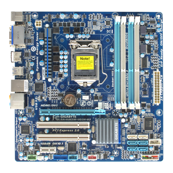
Page 8: Ga-Ha65M-Ud3H-B3 Motherboard Layout
GA-HA65M-UD3H-B3 Motherboard Layout KB_USB PHASE LED ATX_12V LGA1155 HDMI USB30_20 USB_LAN Etron EJ168 CPU_FAN AUDIO PCIEX16 Realtek GA-HA65M-UD3H-B3 Marvell RTL8111E PCI1 88SE9172 PCIe to ® Intel PCI2 PCI Bridge GSATA3_5 GSATA3_4 SATA2_1 SATA2_0 PCIEX1 CODEC Etron EJ168 CLR_CMOS SATA2_3 SATA2_2... -
Page 9: Ga-Ha65M-Ud3H-B3 Motherboard Block Diagram
GA-HA65M-UD3H-B3 Motherboard Block Diagram 1 PCI Express x16 CPU CLK+/- (100 MHz) DDR3 1333/1066/800 MHz LGA1155 Dual Channel Memory PCIe CLK 2 SATA 6Gb/s (100 MHz) Marvell 88SE9172 PCI Express Bus PCIe CLK (100 MHz) PCI Express Bus D-Sub 4 USB 3.0/2.0... -
Page 10: Chapter 1 Hardware Installation
Chapter 1 Hardware Installation Installation Precautions The motherboard contains numerous delicate electronic circuits and components which can become damaged as a result of electrostatic discharge (ESD). Prior to installation, carefully read the user's manual and follow these procedures: Prior to installation, do not remove or break motherboard S/N (Serial Number) sticker or warranty sticker provided by your dealer. - Page 11 Support for Intel Core i7 processors/Intel Core i5 processors/ ® ™ ® ™ Intel Core i3 processors/Intel Pentium processors/Intel Celeron processors ® ™ ® ® ® ® in the LGA1155 package (Go to GIGABYTE's website for the latest CPU support list.) L3 cache varies with CPU Chipset Intel...
- Page 12 Chipset: Up to 8 USB 2.0/1.1 ports (4 on the back panel, 4 via the USB brackets connected to the internal USB headers) 2 x Etron EJ168 chips: Up to 4 USB 3.0/2.0 ports (2 on the back panel, 2 via the USB brackets connected to the internal USB headers) Internal 1 x 24-pin ATX main power connector...
- Page 13 Unique Features Support for @BIOS Support for Q-Flash Support for Xpress BIOS Rescue Support for Download Center Support for Xpress Install Support for Xpress Recovery2 Support for EasyTune * Available functions in EasyTune may differ by motherboard model. Support for Dynamic Energy Saver ™...
-
Page 14: Installing The Cpu And Cpu Cooler
Installing the CPU and CPU Cooler Read the following guidelines before you begin to install the CPU: Make sure that the motherboard supports the CPU. (Go to GIGABYTE's website for the latest CPU support list.) Always turn off the computer and unplug the power cord from the power outlet before installing the CPU to prevent hardware damage. - Page 15 B. Follow the steps below to correctly install the CPU into the motherboard CPU socket. Before installing the CPU, make sure to turn off the computer and unplug the power cord from the power outlet to prevent damage to the CPU. Step 1: Step 2: Gently press the CPU socket lever handle down...
-
Page 16: Installing The Cpu Cooler
1-3-2 Installing the CPU Cooler Follow the steps below to correctly install the CPU cooler on the motherboard. (The following procedure uses ® Intel boxed cooler as the example cooler.) Male Push Direction of the Arrow Sign on The Top the Male Push of Female Push Pin... -
Page 17: Installing The Memory
Installing the Memory Read the following guidelines before you begin to install the memory: Make sure that the motherboard supports the memory. It is recommended that memory of the same capacity, brand, speed, and chips be used. (Go to GIGABYTE's website for the latest supported memory speeds and memory modules.) Always turn off the computer and unplug the power cord from the power outlet before installing the memory to prevent hardware damage. -
Page 18: Installing A Memory
1-4-2 Installing a Memory Before installing a memory module, make sure to turn off the computer and unplug the power cord from the power outlet to prevent damage to the memory module. DDR3 and DDR2 DIMMs are not compatible to each other or DDR DIMMs. Be sure to install DDR3 DIMMs on this motherboard. -
Page 19: Installing An Expansion Card
Installing an Expansion Card Read the following guidelines before you begin to install an expansion card: Make sure the motherboard supports the expansion card. Carefully read the manual that came with your expansion card. Always turn off the computer and unplug the power cord from the power outlet before installing an expansion card to prevent hardware damage. -
Page 20: Back Panel Connectors
Back Panel Connectors USB 2.0/1.1 Port PS/2 Keyboard/Mouse Port Use this port to connect a PS/2 mouse or keyboard. D-Sub Port The D-Sub port supports a 15-pin D-Sub connector. Connect a monitor that supports D-Sub connection to this port. (Note) DVI-D Port (the actual resolutions supported depend on the monitor being used). - Page 21 This motherboard provides three video output ports: D-Sub, DVI-D, and HDMI. BIOS Setup or POST process. USB 3.0/2.0 Port RJ-45 LAN Port The Gigabit Ethernet LAN port provides Internet connection at up to 1 Gbps data rate. The following describes the states of the LAN port LEDs. Connection/ Connection/Speed LED: Activity LED:...
-
Page 22: Internal Connectors
Internal Connectors ATX_12V F_AUDIO SPDIF_O CPU_FAN F_USB1/2 SYS_FAN F_USB30 GSATA3_4/5 CLR_CMOS SATA2_0/1/2/3 PHASE LED F_PANEL Read the following guidelines before connecting external devices: First make sure your devices are compliant with the connectors you wish to connect. Before installing the devices, be sure to turn off the devices and your computer. Unplug the power cord from the power outlet to prevent damage to the devices. - Page 23 1/2) ATX_12V/ATX (2x2 12V Power Connector and 2x12 Main Power Connector) With the use of the power connector, the power supply can supply enough stable power to all the com- is turned off and all devices are properly installed. The power connector possesses a foolproof design. Connect the power supply cable to the power connector in the correct orientation.
- Page 24 3/4) CPU_FAN/SYS_FAN (Fan Headers) The motherboard has a 4-pin CPU fan header (CPU_FAN), a 4-pin system fan header (SYS_FAN). Most fan headers possess a foolproof insertion design. When connecting a fan cable, be sure to connect it in the correct orientation (the black connector wire is the ground wire). The motherboard supports CPU fan speed control, which requires the use of a CPU fan with fan speed control design.
- Page 25 6) GSATA3_4/5 (SATA 6Gb/s Connectors, Controlled by Marvell 88SE9172 Chip) The SATA connector conform to SATA 6Gb/s standard and are compatible with SATA 3Gb/s and SATA 1.5Gb/s standard. Each SATA connector supports a single SATA device. The Marvell 88SE9172 Chip Pin No.
-
Page 26: F_Panel Front Panel Header
8) F_PANEL (Front Panel Header) Connect the power switch, reset switch, speaker, chassis intrusion switch/sensor and system status indicator on the chassis to this header according to the pin assignments below. Note the positive and negative pins before connecting the cables. Message/Power/ Power Speaker... - Page 27 9) F_AUDIO (Front Panel Audio Header) your chassis front panel audio module to this header. Make sure the wire assignments of the module con- nector match the pin assignments of the motherboard header. Incorrect connection between the module connector and the motherboard header will make the device unable to work or even damage it. For HD Front Panel Audio: For AC'97 Front Panel Audio: Pin No.
- Page 28 11) F_USB1/2 (USB 2.0/1.1 Headers) optional USB bracket. For purchasing the optional USB bracket, please contact the local dealer. Pin No. Power (5V) Power (5V) USB DX- USB DY- USB DX+ USB DY+ No Pin When the system is in S4/S5 mode, only the USB ports routed to the F_USB1 header can sup- port the ON/OFF Charge function.
- Page 29 13) COM (Serial Port Header) The COM header can provide one serial port via an optional COM port cable. For purchasing the op- tional COM port cable, please contact the local dealer. Pin No. NDCD- NSIN NSOUT NDTR- NDSR- NRTS- NCTS- NRI- No Pin...
- Page 30 15) PHASE LED The number of lighted LEDs indicates the CPU loading. The higher the CPU loading, the more the ™ ™ Saver 2. Refer to Chapter 4, "Dynamic Energy Saver 2," for more details. - 29 - Hardware Installation...
- Page 31 Hardware Installation - 30 -...
-
Page 32: Chapter 2 Bios Setup
Chapter 2 BIOS Setup BIOS (Basic Input and Output System) records hardware parameters of the system in the CMOS on the motherboard. Its major functions include conducting the Power-On Self-Test (POST) during system startup, saving system parameters and loading operating system, etc. BIOS includes a BIOS Setup program that the power is turned off, the battery on the motherboard supplies the necessary power to the CMOS to keep To access the BIOS Setup program, press the <Delete>... -
Page 33: Startup Screen
Startup Screen The following screens may appear when the computer boots. A. The LOGO Screen (Default) Function Keys B. The POST Screen Award Modular BIOS v6.00PG Copyright (C) 1984-2011, Award Software, Inc. HA65M-UD3H-B3 E6x Motherboard Model BIOS Version Function Keys <DEL>: BIOS Setup <F9>: XpressRecovery2 <F12>: Boot Menu <End>: Qflash 01/20/2011-H61-7A89VG04C-00 Function Keys:... -
Page 34: The Main Menu
The Main Menu Once you enter the BIOS Setup program, the Main Menu (as shown below) appears on the screen. Use ar- row keys to move among the items and press <Enter> to accept or enter a sub-menu. (Sample BIOS Version: E6x) CMOS Setup Utility-Copyright (C) 1984-2011 Award Software MB Intelligent Tweaker(M.I.T.) Load Fail-Safe Defaults... - Page 35 The Functions of the <F11> and <F12> keys (For the Main Menu Only) F11: Save CMOS to BIOS the SPACE key) and then press <Enter> to complete. F12: Load CMOS from BIOS If your system becomes unstable and you have loaded the BIOS default settings, you can use this MB Intelligent Tweaker(M.I.T.) Standard CMOS Features type of errors that stop the system boot, etc.
-
Page 36: Mb Intelligent Tweaker(M.i.t.)
MB Intelligent Tweaker(M.I.T.) CMOS Setup Utility-Copyright (C) 1984-2011 Award Software MB Intelligent Tweaker(M.I.T.) Item Help M.I.T Current Status [Press Enter] Menu Level Advanced Frequency Settings [Press Enter] Advanced Memory Settings [Press Enter] Advanced Voltage Settings [Press Enter] Miscellaneous Settings [Press Enter] BIOS Version BCLK 99.80 MHz... - Page 37 M.I.T. Current Status This screen provides information on CPU/memory frequencies/parameters. Advanced Frequency Settings CMOS Setup Utility-Copyright (C) 1984-2011 Award Software Advanced Frequency Settings Item Help CPU Clock Ratio [31X] Menu Level CPU Frequency 3.10GHz (100x31) Advanced CPU Core Features [Press Enter] >>>>>...
- Page 38 CPU Clock Ratio Allows you to alter the clock ratio for the installed CPU. The adjustable range is dependent on the CPU being installed. CPU Frequency Displays the current operating CPU frequency. (Note) Intel(R) Turbo Boost Tech. Allows you to determine whether to enable the Intel CPU Turbo Boost technology. Auto lets the BIOS (Note) Turbo Ratio (1-Core)/(2-Core)/(3-Core)/(4-Core) Allows you to set the CPU Turbo ratios for different number of active cores.
- Page 39 (Note) CPU EIST Function Enables or disables Enhanced Intel Speed Step Technology (EIST). Depending on CPU loading, Intel EIST technology can dynamically and effectively lower the CPU voltage and core frequency to decrease average power consumption and heat production. Auto ting.
- Page 40 Advanced Memory Settings CMOS Setup Utility-Copyright (C) 1984-2011 Award Software Advanced Memory Settings Item Help System Memory Multiplier (SPD) [Auto] Menu Level Memory Frequency(Mhz) 1333 1333 Performance Enhance [Turbo] DRAM Timing Selectable (SPD) [Auto] x Channel Interleaving Auto x Rank Interleaving Auto >>>>>...
- Page 41 >>>>> Channel A/B Timing Settings CMOS Setup Utility-Copyright (C) 1984-2011 Award Software Channel A Timing Settings Item Help >>>>> Channel A Standard Timing Control Menu Level x CAS Latency Time Auto x tRCD Auto x tRP Auto x tRAS Auto >>>>>...
- Page 42 Command Rate(CMD) Options are: Auto (default), 1~3. >>>>> Channel A/B Misc Timing Control IO Latency Options are: Auto (default), 1~31. Round Trip Latency Options are: Auto (default), 1~255. Advanced Voltage Settings CMOS Setup Utility-Copyright (C) 1984-2011 Award Software Advanced Voltage Settings Item Help ****** Mother Board Voltage Control ****** Menu Level...
-
Page 43: Miscellaneous Settings
Miscellaneous Settings CMOS Setup Utility-Copyright (C) 1984-2011 Award Software Miscellaneous Settings Item Help Isochronous Support [Enabled] Menu Level (Note) Virtualization Technology [Enabled] : Move Enter: Select +/-/PU/PD: Value F10: Save ESC: Exit F1: General Help F5: Previous Values F6: Fail-Safe Defaults F7: Optimized Defaults Isochronous Support (Note) -
Page 44: Standard Cmos Features
Standard CMOS Features CMOS Setup Utility-Copyright (C) 1984-2011 Award Software Standard CMOS Features Item Help Date (mm:dd:yy) Tue, Jan 25 2011 Menu Level Time (hh:mm:ss) 22:31:24 IDE Channel 0 Master [None] IDE Channel 1 Master [None] IDE Channel 2 Master [None] IDE Channel 3 Master [None]... - Page 45 refer to the information on the hard drive. Capacity Approximate capacity of the currently installed hard drive. Cylinder Number of cylinders. Head Number of heads. Precomp Write precompensation cylinder. Landing Zone Landing zone. Sector Number of sectors. Halt On Allows you to determine whether the system will stop for an error during the POST. All Errors Whenever the BIOS detects a non-fatal error the system boot will stop.
-
Page 46: Advanced Bios Features
Advanced BIOS Features CMOS Setup Utility-Copyright (C) 1984-2011 Award Software Advanced BIOS Features Item Help Hard Disk Boot Priority [Press Enter] Menu Level Quick Boot [Disabled] CD/DVD Boot option [Auto] First Boot Device [Hard Disk] Second Boot Device [CDROM] Third Boot Device [USB-FDD] Password Check [Setup]... - Page 47 HDD S.M.A.R.T. Capability Enables or disables the S.M.A.R.T. (Self Monitoring and Reporting Technology) capability of your hard drive. This feature allows your system to report read/write errors of the hard drive and to issue warnings when a third party hardware monitor utility is installed. (Default: Disabled) (Note) Limit CPUID Max.
-
Page 48: Integrated Peripherals
Integrated Peripherals CMOS Setup Utility-Copyright (C) 1984-2011 Award Software Integrated Peripherals Item Help SATA Port0-1 Native Mode [Enabled] Menu Level USB Controllers [Enabled] USB Legacy Function [Enabled] USB Storage Function [Enabled] Azalia Codec [Auto] Onboard H/W LAN [Enabled] SMART LAN [Press Enter] Onboard LAN Boot ROM [Disabled]... - Page 49 SMART LAN (LAN Cable Diagnostic Function) CMOS Setup Utility-Copyright (C) 1984-2011 Award Software SMART LAN Item Help Start detecting at Port..Menu Level Part1-2 Status = Open / Length = Part3-6 Status = Open / Length = Part4-5 Status = Open / Length = Part7-8 Status = Open / Length = : Move Enter: Select...
- Page 50 Onboard LAN Boot ROM Allows you to decide whether to activate the boot ROM integrated with the onboard LAN chip. (Default: Disabled) R_USB30 Controller (Etron EJ168 USB Controller, USB 3.0/2.0 ports on the back panel) Enables or disables the Etron EJ168 USB controller. (Default: Enabled) F_USB30 Controller (Etron EJ168 USB Controller, USB 3.0/2.0 ports routed to the on board F_USB30 header) Enables or disables the Etron EJ168 USB controller.
-
Page 51: Power Management Setup
Power Management Setup CMOS Setup Utility-Copyright (C) 1984-2011 Award Software Power Management Setup Item Help ACPI Suspend Type [S3(STR)] Menu Level Soft-Off by PWR-BTTN [Instant-Off] PME Event Wake Up [Enabled] Power On By Ring [Enabled] Resume by Alarm [Disabled] Date (of Month) Alarm Everyday Time (hh:mm:ss) Alarm 0 : 0 : 0... - Page 52 Resume by Alarm Determines whether to power on the system at a desired time. (Default: Disabled) If enabled, set the date and time as following: month. Time (hh: mm: ss) Alarm: Set the time at which the system will be powered on automatically. Note: When using this function, avoid inadequate shutdown from the operating system or removal of the AC power, or the settings may not be effective.
-
Page 53: Pc Health Status
PC Health Status CMOS Setup Utility-Copyright (C) 1984-2011 Award Software PC Health Status Item Help Reset Case Open Status [Disabled] Menu Level Case Opened Vcore 1.224V DDR15V 1.524V +12V 12.073V 1.076V Current System Temperature Current CPU Temperature Current CPU FAN Speed 2777 RPM Current SYSTEM FAN Speed 0 RPM... - Page 54 CPU Smart FAN Control Allows you to determine whether to enable the CPU fan speed control function and adjust the fan speed. Normal Allows the CPU fan to run at different speeds according to the CPU temperature. You can adjust the fan speed with EasyTune based on your system requirements. (Default) Silent Allows the CPU fan to run at slow speeds.
-
Page 55: Load Fail-Safe Defaults
Load Fail-Safe Defaults CMOS Setup Utility-Copyright (C) 1984-2011 Award Software MB Intelligent Tweaker(M.I.T.) Load Fail-Safe Defaults Standard CMOS Features Load Optimized Defaults Advanced BIOS Features Set Supervisor Password Integrated Peripherals Set User Password Power Management Setup Save & Exit Setup Load Fail-Safe Defaults (Y/N)? N PC Health Status Exit Without Saving... -
Page 56: Set Supervisor/User Password
2-11 Set Supervisor/User Password CMOS Setup Utility-Copyright (C) 1984-2011 Award Software MB Intelligent Tweaker(M.I.T.) Load Fail-Safe Defaults Standard CMOS Features Load Optimized Defaults Advanced BIOS Features Set Supervisor Password Integrated Peripherals Set User Password Power Management Setup Save & Exit Setup Enter Password: PC Health Status Exit Without Saving... -
Page 57: Save & Exit Setup
2-12 Save & Exit Setup CMOS Setup Utility-Copyright (C) 1984-2011 Award Software MB Intelligent Tweaker(M.I.T.) Load Fail-Safe Defaults Standard CMOS Features Load Optimized Defaults Save to CMOS and EXIT (Y/N)? Y Advanced BIOS Features Set Supervisor Password Integrated Peripherals Set User Password Power Management Setup Save &... -
Page 58: Chapter 3 Drivers Installation
Chapter 3 Drivers Installation After installing the operating system, insert the motherboard driver disk into your optical drive. The driver Autorun screen is automatically displayed which looks like that shown in the screen shot below. (If the driver Autorun screen does not appear automatically, go to My Computer, double-click the optical drive and execute the Run.exe program.) Installing Chipset Drivers After inserting the driver disk, "Xpress Install"... -
Page 59: Application Software
Application Software This page displays all the utilities and applications that GIGABYTE develops and some free software. You can click the Install button on the right of an item to install it. Technical Manuals This page provides GIGABYTE's application guides, content descriptions for this driver disk, and the mother- board manuals. -
Page 60: Contact
Contact the URL on this page to link to the GIGABYTE website. System This page provides the basic system information. - 59 - Drivers Installation... -
Page 61: Download Center
Download Center To update the BIOS, drivers, or applications, click the Download Center button to link to the GIGABYTE website. The latest version of the BIOS, drivers, or applications will be displayed. New Utilities This page provides a quick link to GIGABYTE's lately developed utilities for users to install. You can click the Install button on the right of an item to install it. -
Page 62: Chapter 4 Unique Features
Chapter 4 Unique Features Xpress Recovery2 Xpress Recovery2 is a utility that allows you to quickly compress and back up your system data and perform restoration of it. Supporting NTFS, PATA and SATA hard drives and restore it. Before You Begin: allocated space in advanced (10 GB or more is recommended;... - Page 63 Step 3: Step 4: When partitioning your hard drive, make sure to After the operating system is installed, click Start, leave unallocated space (10 GB or more is recom- right-click the Computer and select Manage. Go to mended; actual size requirements vary, depending Disk Management to check disk allocation.
- Page 64 D. Using the Restore Function in Xpress Recovery2 Select RESTORE to restore the backup to your hard drive in case the system breaks down. The RESTORE option will not be present if no backup is created before. E. Removing the Backup Step 1: Step 2: REMOVE.
-
Page 65: Bios Update Utilities
BIOS Update Utilities ™ ™ GIGABYTE motherboards provide two unique BIOS update tools, Q-Flash and @BIOS . GIGABYTE Q-Flash and @BIOS are easy-to-use and allow you to update the BIOS without the need to enter MS-DOS ™ mode. Additionally, this motherboard features the DualBIOS design, which enhances protection for the safety and stability of your computer by adding one more physical BIOS chip. - Page 66 B. Updating the BIOS Step 1: the up or down arrow key to select Update BIOS from Drive and press <Enter>. The Save Main BIOS to Drive an independent SATA controller, use the <End> key during the POST to access Q-Flash. Select HDD 1-0 and press <Enter>.
- Page 67 Step 4: Press <Esc> and then <Enter> to exit Q-Flash and reboot the system. As the system boots, you should see the new BIOS version is present on the POST screen. Step 5: During the POST, press <Delete> to enter BIOS Setup. Select Load Optimized Defaults and press <Enter> to load BIOS defaults.
-
Page 68: Updating The Bios With The @Bios Utility
4-2-2 Updating the BIOS with the @BIOS Utility A. Before You Begin In Windows, close all applications and TSR (Terminate and Stay Resident) programs. This helps prevent unexpected failures when performing a BIOS update. During the BIOS update process, ensure the Internet connection is stable and do NOT interrupt the Internet connection (for example, avoid a power loss or switching off the Internet). -
Page 69: Easytune 6
EasyTune 6 settings or do overclock/overvoltage in Windows environment. The user-friendly EasyTune 6 interface also includes tabbed pages for CPU and memory information, letting users read their system-related information without the need to install additional software. The EasyTune 6 Interface Tabs Information Function The CPU tab provides information on the installed CPU and motherboard. -
Page 70: Dynamic Energy Saver
Dynamic Energy Saver ™ ™ (Note 1) GIGABYTE Dynamic Energy Saver is a revolutionary technology that delivers unparalleled power savings with a click of the button. Featuring an advanced proprietary hardware and software design, GIGA- ™ BYTE Dynamic Energy Saver ™... - Page 71 B. Total Mode In Total Mode, users are able to see how much total power savings they have accumulated in a set period of ™ (Note 3) time since activating Dynamic Energy Saver 2 for th 11 12 13 Total Mode - Button Information Table Button Description Dynamic Energy Saver On/Off Switch (Default: Off) Current CPU Power Consumption...
-
Page 72: Q-Share
Q-Share Q-Share is an easy and convenient data sharing too Q-Share, you are able to share your data with computers on the same network, making full use of Internet resources. Directions for using Q-Share After installing Q-Share from the motherboard driver disk, go to Start>All Programs>GIGABYTE>Q-Share. exe to launch the Q-Share tool. -
Page 73: Smart 6
™ Smart 6 ™ (Note 1) GIGABYTE Smart 6 is designed with user-friendliness in mind, and offers a combination of 6 innovative ™ software utilities that provide easier and smarter PC system management. Smart 6 allows you to speed up click of the mouse button. - Page 74 SMART Recovery 2 The Smart Recovery 2 main menu: Button Function Settings Allows you to select the source and destination partition Backup Now Allows you to perform the backup immediately File Recovery... System Recovery... Allows you to recover your system from the backup image Supported operating systems: Windows 7 and Vista.
- Page 75 Recovering your system with Smart Recovery 2 (Windows 7 only): Steps: 1. Click the System Recovery button on the main menu. 2. Select the partition where your backup is saved. 3. Use the time slider to select a time point. 4.
- Page 76 SMART Recorder SMART Recorder monitors and records the activities in a system such as the time when the (Note 2) copied to an external storage device Instructions: Select the Enable check box at the bottom of the ON/OFF Recorder or File Monitor tab to enable the recording of system on/off time or ™...
-
Page 77: Auto Green
Auto Green Auto Green is an easy-to-use tool that provides users with simple options to enable system power savings via a Bluetooth cell phone. When the phone is out of the range of the computer's Bluetooth receiver, the sys- First, you have to set your Bluetooth cell phone as a portable key. On the Auto Green main menu, click and then click . -
Page 78: Cloud Oc
Cloud OC (Note 1) Cloud OC is an easy-to-use overclocking utility designed for system overclock- ing via virtually any Internet-connected device, such as a smart phone, iPhone, note- book PC, etc. By simply connecting to an Internet browser via LAN, wireless LAN, or (Note 2) Bluetooth and logging in to the Cloud OC server, you can easily access three major functions of Cloud... - Page 79 Unique Features - 78 -...
-
Page 80: Chapter 5 Appendix
Chapter 5 Appendix A. Install SATA hard drive(s) in your computer. (Note 1) (Note 2) D. Install the SATA RAID/AHCI driver and operating system. Before you begin Please prepare: At least two SATA hard drives (to ensure optimal performance, it is recommended that you use two hard drives with identical model and capacity). - Page 81 Step 1: Turn on your computer and press <Delete> to enter BIOS Setup during the POST. In BIOS Setup, go to In- tegrated Peripherals. To enable RAID, set GSATA3 Controller to Enabled and set GSATA3 Ctrl Mode to RAID. CMOS Setup Utility-Copyright (C) 1984-2011 Award Software Integrated Peripherals Item Help SATA Port0-1 Native Mode...
- Page 82 After the POST memory test begins and before the operating system boot begins, look for a message which says "Press <Ctrl>+<M> to enter BIOS Setup or <Space> to continue" (Figure 2). Press <Ctrl> + <M> to en- ter the RAID setup utility. Marvell 88SE91xx Adapter - BIOS Version 1.0.0.0017 PCIe x2 5.0Gbps Mode: RAID...
- Page 83 Create a RAID Array: Step 1: On the main screen, press <Enter> on the RAID tab. Then the menu appears (Figure 4). Press <Enter> on the Create VD item. Marvell BIOS Setup (c) 2009 Marvell Technology Group Ltd. [ Selection] [ Adapter] [ Devices] [ RAID ]...
- Page 84 Step 3: On the Create VD menu (Figure 6), use the up or down arrow key to move the selection bar to select an item and press <Enter> to display options. Set the required items in sequence and press the down arrow key to proceed to the next item.
- Page 85 When completed, the RAID tab will display the new array. (Figure 8) Marvell BIOS Setup (c) 2009 Marvell Technology Group Ltd. [ Selection] [ Adapter] [ Devices] [ RAID ] [Virtual Disks] Name Size Level Status Stripe CacheMode 152.4GB RAID0 ONLINE 64KB WriteBack...
- Page 86 Use the Marvell Storage Utility in the Operating System: With the Marvell Storage utility, you can set up an array or view the current array status in the operating system. To install the utility, insert the motherboard driver disk, then go to Application Software\Install Ap- plication Software and select Marvell Storage Utility to install.
-
Page 87: Installing The Sata Raid/Ahci Driver And Operating System
5-1-2 Installing the SATA RAID/AHCI Driver and Operating System With the correct BIOS settings, you are ready to install Windows 7/Vista/XP. A. Installing Windows 7/Vista (The following instructions use Windows 7 as the example operating system.) Step 1: Boot from the Windows 7/Vista setup disk and perform standard OS installation steps. When you arrive at the "Where do you want to install Windows?"... - Page 88 B. Installing Windows XP To install Windows XP, you need to install the SATA RAID/AHCI driver during the OS installation. Without the driver, the hard drive(s) may not be recognized during the Windows setup process. First, copy the driver from Method A: For the Marvell 88SE9172, \BootDrv\Marvell\RAID...
- Page 89 installing the driver during the Windows setup process. Step 1: Restart your system to boot from the Windows XP setup disk and press <F6> as soon as you see the mes- sage "Press F6 if you need to install a 3rd party SCSI or RAID driver." A screen will then appear asking you to specify an additional SCSI adapter.
- Page 90 C. Rebuilding an Array Rebuilding is the process of restoring data to a hard drive from other drives in the array. Rebuilding applies only to fault-tolerant arrays such as RAID 1 array. The procedures below assume a new drive is added to re- place a failed drive to rebuild a RAID 1 array.
- Page 91 Step 3: Make sure you have installed the Marvell RAID driver and Marvell Storage Utility from the motherboard driver disk. While in the operating system, launch the Marvell Storage Utility from Start\All Programs\Marvell Storage Utility\Marvell Tray, right-click on the Open MSU. Then login the Marvell Storage Utility.
- Page 92 The motherboard provides six audio jacks on the back (Note) panel which support 2/4/5.1/7.1-channel audio. The picture to the right shows the default audio jack Center/Subwoofer Line In Speaker Out assignments. Rear Speaker Out Front Speaker Out The integrated HD (High Definition) audio provides Side Mic In jack retasking capability that allows the user to change...
- Page 93 Step 2: Connect an audio device to an audio jack. The The cur- rent connected device is dialog box appears. Select the device according to the type of device you connect. Then click OK. Step 3: On the Speakers screen, click the tion tab.
- Page 94 Enter the Digital Output (SPDIF_O) for digital audio output. Step 1: After installing the audio driver, the HD Audio Manager icon the icon to access the HD Audio Manager. Step 2: Connect your microphone to the Mic in jack (pink) on the back panel or the Mic in jack (pink) on the front ality.
- Page 95 Step 3: Go to the Microphone screen. Do not mute the record- ing volume, or you'll not be able to record the sound. To hear the sound being recorded during the recording process, do not mute the playback volume. It is recom- mended that you set the volumes at a middle level.
- Page 96 * Enabling Stereo Mix If the HD Audio Manager does not display the recording device you wish to use, refer to the steps below. The following steps explain how to enable Stereo Mix (which may be needed when you want to record sound from your computer).
-
Page 97: Using The Sound Recorder
Step 4: Now you can access the HD Audio Manager ure Stereo Mix and use Sound Recorder to record the sound. 5-2-4 Using the Sound Recorder A. Recording Sound 1. Make sure you have connected the sound input device (e.g. microphone) to the computer. 2. -
Page 98: Troubleshooting
Troubleshooting 5-3-1 Frequently Asked Questions To read more FAQs for your motherboard, please go to the Support & Downloads\FAQ page on GIGABYTE's website. Q: In the BIOS Setup program, why are some BIOS options missing? A: Some advanced options are hidden in the BIOS Setup program. Press <Delete> to enter BIOS Setup during the POST. In the Main Menu, press <Ctrl>+<F1>... -
Page 99: Troubleshooting Procedure
5-3-2 Troubleshooting Procedure If you encounter any troubles during system startup, follow the troubleshooting procedure below to solve the problem. START Turn off the power. Remove all peripherals, connecting cables, and power cord etc. Make sure the motherboard does not short-circuit with the chassis or Isolate the short circuit. - Page 100 The power supply, CPU or When the computer is turned on, is the CPU cooler running? CPU socket might fail. The graphics card, expansion slot, or monitor Check if there is display on your monitor. might fail. Turn off the computer. Plug in the keyboard and mouse and restart the computer.
- Page 101 Appendix - 100 -...
- Page 102 - 101 - Appendix...
- Page 103 Appendix - 102 -...
- Page 104 Shenyang Web address: http://latam.giga-byte.com TEL: +86-24-83992901 Giga-Byte SINGAPORE PTE. LTD. - Singapore FAX: +86-24-83992909 WEB address : http://www.gigabyte.sg GIGABYTE TECHNOLOGY (INDIA) LIMITED - India Thailand WEB address : http://www.gigabyte.in WEB address : http://th.giga-byte.com Saudi Arabia Vietnam WEB address : http://www.gigabyte.com.sa WEB address : http://www.gigabyte.vn...
- Page 105 WEB address : http://www.giga-byte.co.uk WEB address : http://www.gigabyte.com.tr Giga-Byte Technology B.V. - The Netherlands Russia WEB address : http://www.giga-byte.nl WEB address : http://www.gigabyte.ru GIGABYTE TECHNOLOGY FRANCE - France Poland WEB address : http://www.gigabyte.fr WEB address : http://www.gigabyte.pl Sweden Ukraine WEB address : http://www.gigabyte.se WEB address : http://www.gigabyte.ua...
- Page 106 GigaByte GA-HA65M-UD3H-B3 rev. 1.0 Описание Характеристики...
Need help?
Do you have a question about the GA-HA65M-UD3H-B3 and is the answer not in the manual?
Questions and answers