Table of Contents
Advertisement
Advertisement
Table of Contents
Troubleshooting

Related Manuals for Gigabyte GA-Z77N-WIFI


Summary of Contents for Gigabyte GA-Z77N-WIFI
- Page 1 GA-Z77N-WIFI GA-H77N-WIFI User's Manual Rev. 1002 12ME-Z77NWIF-1002R...
- Page 2 Motherboard GA-Z77N-WIFI/GA-H77N-WIFI Motherboard GA-Z77N-WIFI GA-H77N-WIFI Aug. 24, 2012 Aug. 24, 2012 Wireless Module Country Approvals:...
-
Page 3: Identifying Motherboard Revision
Copyright © 2012 GIGA-BYTE TECHNOLOGY CO., LTD. All rights reserved. The trademarks mentioned in this manual are legally registered to their respective owners. Disclaimer Information in this manual is protected by copyright laws and is the property of GIGABYTE. without prior notice. No part of this manual may be reproduced, copied, translated, transmitted, or published in any form or by any means without GIGABYTE's prior written permission. -
Page 4: Table Of Contents
Table of Contents Box Contents ........................6 Optional Items .........................6 GA-Z77N-WIFI/GA-H77N-WIFI Motherboard Layout ............7 GA-Z77N-WIFI/GA-H77N-WIFI Motherboard Block Diagram .........8 Chapter 1 Hardware Installation ..................9 Installation Precautions ..................9 ..................10 Installing the CPU and CPU Cooler ............... 13 1-3-1 Installing the CPU ....................13 1-3-2 Installing the CPU Cooler ..................15... - Page 5 Chapter 4 Unique Features ...................59 BIOS Update Utilities ..................59 4-1-1 Updating the BIOS with the Q-Flash Utility .............59 4-1-2 Updating the BIOS with the @BIOS Utility .............62 EasyTune 6 ....................63 Q-Share ......................64 eXtreme Hard Drive (X.H.D) ................65 Auto Green .....................
-
Page 6: Box Contents
Box Contents GA-Z77N-WIFI or GA-H77N-WIFI motherboard Two motherboard driver disks User's Manual Two SATA 6Gb/s cables I/O Shield The box contents above are for reference only and the actual items shall depend on the product package you obtain. The box contents are subject to change without notice. -
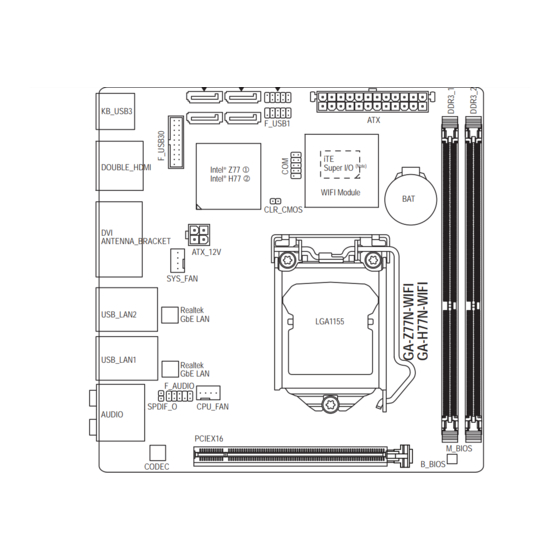
Page 7: Ga-Z77N-Wifi/Ga-H77N-Wifi Motherboard Layout
GA-Z77N-WIFI/GA-H77N-WIFI Motherboard Layout SATA3_0 SATA2_3 F_PANEL SATA3_1 SATA2_2 KB_USB3 F_USB1 DOUBLE_HDMI Super I/O (Note) Intel ® Intel ® WIFI Module CLR_CMOS ANTENNA_BRACKET ATX_12V SYS_FAN Realtek USB_LAN2 GbE LAN LGA1155 USB_LAN1 Realtek GbE LAN F_AUDIO SPDIF_O CPU_FAN AUDIO PCIEX16 M_BIOS B_BIOS CODEC Only for GA-Z77N-WIFI. -
Page 8: Ga-Z77N-Wifi/Ga-H77N-Wifi Motherboard Block Diagram
GA-Z77N-WIFI/GA-H77N-WIFI Motherboard Block Diagram 1 PCI Express x16 CPU CLK+/- (100 MHz) PCIe CLK LGA1155 (100 MHz) DDR3 1600/1333/1066/800 MHz Dual Channel Memory PCI Express Bus HDMI RJ45 RJ45 DVI-I Realtek Realtek GbE LAN GbE LAN Dual BIOS PCI Express Bus 4 USB 3.0/2.0... -
Page 9: Chapter 1 Hardware Installation
Chapter 1 Hardware Installation Installation Precautions The motherboard contains numerous delicate electronic circuits and components which can become damaged as a result of electrostatic discharge (ESD). Prior to installation, carefully read the user's manual and follow these procedures: Prior to installation, make sure the chassis is suitable for the motherboard. Prior to installation, do not remove or break motherboard S/N (Serial Number) sticker or warranty sticker provided by your dealer. - Page 10 Up to 4 USB 3.0/2.0 ports (2 ports on the back panel, 2 ports available through the internal USB header) Up to 6 USB 2.0/1.1 ports (4 ports on the back panel, 2 ports available through the internal USB header) Only for GA-Z77N-WIFI. Only for GA-H77N-WIFI. Hardware Installation - 10 -...
- Page 11 Internal 1 x 24-pin ATX main power connector Connectors 1 x 4-pin ATX 12V power connector 2 x SATA 6Gb/s connectors 2 x SATA 3Gb/s connectors 1 x USB 3.0/2.0 header 1 x USB 2.0/1.1 header 1 x CPU fan header 1 x system fan header 1 x front panel header 1 x front panel audio header...
- Page 12 Unique Features Support for @BIOS Support for Q-Flash Support for Xpress Install Support for EasyTune * Available functions in EasyTune may differ by motherboard model. Support for eXtreme Hard Drive (X.H.D) Support for Auto Green Support for ON/OFF Charge Support for Q-Share Support for EZ Setup Bundled Software Norton Internet Security (OEM version)
-
Page 13: Installing The Cpu And Cpu Cooler
Installing the CPU and CPU Cooler Read the following guidelines before you begin to install the CPU: Make sure that the motherboard supports the CPU. (Go to GIGABYTE's website for the latest CPU support list.) Always turn off the computer and unplug the power cord from the power outlet before installing the CPU to prevent hardware damage. - Page 14 B. Follow the steps below to correctly install the CPU into the motherboard CPU socket. Before installing the CPU, make sure to turn off the computer and unplug the power cord from the power outlet to prevent damage to the CPU. Step 1: Step 2: Gently press the CPU socket lever handle down...
-
Page 15: Installing The Cpu Cooler
1-3-2 Installing the CPU Cooler Follow the steps below to correctly install the CPU cooler on the motherboard. (The following procedure uses Intel boxed cooler as the example cooler.) ® Male Push Direction of the Arrow Sign The Top on the Male of Female Push Pin Push Pin... -
Page 16: Installing The Memory
Installing the Memory Read the following guidelines before you begin to install the memory: Make sure that the motherboard supports the memory. It is recommended that memory of the same capacity, brand, speed, and chips be used. (Go to GIGABYTE's website for the latest supported memory speeds and memory modules.) Always turn off the computer and unplug the power cord from the power outlet before installing the memory to prevent hardware damage. -
Page 17: Installing A Memory
1-4-2 Installing a Memory Before installing a memory module, make sure to turn off the computer and unplug the power cord from the power outlet to prevent damage to the memory module. DDR3 and DDR2 DIMMs are not compatible to each other or DDR DIMMs. Be sure to install DDR3 DIMMs on this motherboard. -
Page 18: Installing An Expansion Card
Installing an Expansion Card Read the following guidelines before you begin to install an expansion card: Make sure the motherboard supports the expansion card. Carefully read the manual that came with your expansion card. Always turn off the computer and unplug the power cord from the power outlet before installing an expansion card to prevent hardware damage. -
Page 19: Back Panel Connectors
Back Panel Connectors PS/2 Keyboard/Mouse Port Use this port to connect a PS/2 mouse or keyboard. USB 3.0/2.0 Port HDMI Port uncompressed audio/video signals. The HDMI port is HDCP compliant and supports Dolby TrueHD and DTS HD Master Audio formats. It also supports up to 192KHz/24bit 8-channel LPCM audio output. You can use this port to connect your HDMI-supported audio/video device. - Page 20 DVI-I Port RJ-45 LAN Port USB 2.0/1.1 Port Center/Subwoofer Speaker Out Jack (Orange) Rear Speaker Out Jack (Black) Optical S/PDIF Out Connector Line In Jack (Blue) Line Out Jack (Green) Mic In Jack (Pink) Hardware Installation - 20 -...
-
Page 21: Internal Connectors
Internal Connectors 11 12 ATX_12V F_PANEL F_AUDIO CPU_FAN F_USB30 SYS_FAN F_USB1 SATA3 0/1 SPDIF_O SATA2 2/3 CLR_CMOS Read the following guidelines before connecting external devices: First make sure your devices are compliant with the connectors you wish to connect. Before installing the devices, be sure to turn off the devices and your computer. Unplug the power cord from the power outlet to prevent damage to the devices. - Page 22 1/2) ATX_12V/ATX (2x2 12V Power Connector and 2x12 Main Power Connector) With the use of the power connector, the power supply can supply enough stable power to all the components off and all devices are properly installed. The power connector possesses a foolproof design. Connect the power supply cable to the power connector in the correct orientation.
- Page 23 3/4) CPU_FAN/SYS_FAN (Fan Headers) All fan headers on this motherboard are 4-pin. Most fan headers possess a foolproof insertion design. When connecting a fan cable, be sure to connect it in the correct orientation (the black connector wire is the ground wire). The motherboard supports CPU fan speed control, which requires the use of a CPU fan with fan speed control design.
- Page 24 6) SATA3 0/1 (SATA 6Gb/s Connectors, Controlled by Intel Z77/H77 Chipset) The SATA connectors conform to SATA 6Gb/s standard and are compatible with SATA 3Gb/s and SATA 1.5Gb/s standard. Each SATA connector supports a single SATA device. The "SATA3 0" and "SATA3 1" connectors support RAID 0 and RAID 1.
-
Page 25: F_Panel (Front Panel Header)
8) F_PANEL (Front Panel Header) Connect the power switch, reset switch, and system status indicator on the chassis to this header according to the pin assignments below. Note the positive and negative pins before connecting the cables. Hard Drive Reset Activity LED Switch Power... - Page 26 9) F_AUDIO (Front Panel Audio Header) your chassis front panel audio module to this header. Make sure the wire assignments of the module connector match the pin assignments of the motherboard header. Incorrect connection between the module connector and the motherboard header will make the device unable to work or even damage it. For HD Front Panel Audio: For AC'97 Front Panel Audio: Pin No.
- Page 27 11) F_USB1 (USB Header) optional USB bracket. For purchasing the optional USB bracket, please contact the local dealer. Pin No. Power (5V) Power (5V) USB DX- USB DY- USB DX+ USB DY+ No Pin Do not plug the IEEE 1394 bracket (2x5-pin) cable into the USB header. Prior to installing the USB bracket, be sure to turn off your computer and unplug the power cord from the power outlet to prevent damage to the USB bracket.
-
Page 28: Clear Cmos Jumper
13) SPDIF_O (S/PDIF Out Header) This header supports digital S/PDIF Out and connects a S/PDIF digital audio cable (provided by expansion cards) for digital audio output from your motherboard to certain expansion cards like graphics cards and sound cards. For example, some graphics cards may require you to use a S/PDIF digital audio cable for digital audio output from your motherboard to your graphics card if you wish to connect an HDMI display to the graphics card and have digital audio output from the HDMI display at the same time. -
Page 29: Chapter 2 Bios Setup
Chapter 2 BIOS Setup BIOS (Basic Input and Output System) records hardware parameters of the system in the CMOS on the motherboard. Its major functions include conducting the Power-On Self-Test (POST) during system startup, saving system parameters and loading operating system, etc. BIOS includes a BIOS Setup program that allows When the power is turned off, the battery on the motherboard supplies the necessary power to the CMOS to To access the BIOS Setup program, press the <Delete>... -
Page 30: Startup Screen
Startup Screen The following startup Logo screen will appear when the computer boots. Function Keys Function Keys: <DEL>: BIOS SETUP\Q-FLASH Press the <Delete> key to enter BIOS Setup or to access the Q-Flash utility in BIOS Setup. <F9>: SYSTEM INFORMATION Press the <F9>... -
Page 31: The Main Menu
On the main menu of the BIOS Setup program, press arrow keys to move among the items and press <Enter> to accept or enter a sub-menu. Or you can use your mouse to select the item you want. (Sample BIOS Version: GA-Z77N-WIFI F1c) Setup Menus... - Page 32 BIOS Setup Program Function Keys Move the selection bar to select a setup menu < >< > < >< > <Enter> Execute command or enter a menu <+>/<Page Up> Increase the numeric value or make changes <->/<Page Down> Decrease the numeric value or make changes <F1>...
-
Page 33: M.i.t
M.I.T. Whether the system will work stably with the overclock/overvoltage settings you made is dependent to CPU, chipset, or memory and reduce the useful life of these components. This page is for advanced users only and we recommend you not to alter the default settings to prevent system instability or other unexpected results. - Page 34 M.I.T. Current Status This screen provides information on CPU/memory frequencies/parameters. Advanced Frequency Settings CPU/PCIe Base Clock Allows you to manually set the CPU base clock and PCIe bus frequency in 0.01 MHz increments. (Default: Auto) Processor Graphics Clock Allows you to set the onboard graphics clock. The adjustable range is from 400 MHz to 1600 MHz. (Default: Auto) CPU Clock Ratio Allows you to alter the clock ratio for the installed CPU.
- Page 35 Advanced CPU Core Features CPU Clock Ratio, CPU Frequency The settings above are synchronous to those under the same items on the Advanced Frequency Settings menu. Internal CPU PLL Overvoltage Enabled allows CPU PLL voltage to operate at a higher value. Disabled allows CPU PLL voltage to operate at default value.
- Page 36 Hyper-Threading Technology (Note 1) Allows you to determine whether to enable multi-threading technology when using an Intel CPU that supports this function. This feature only works for operating systems that support multi-processor mode. Auto lets CPU Enhanced Halt (C1E) (Note 1) Enables or disables Intel CPU Enhanced Halt (C1E) function, a CPU power-saving function in system halt state.
- Page 37 Advanced Memory Settings , System Memory Multiplier, Memory Frequency(MHz) (Note) The settings above are synchronous to those under the same items on the Advanced Frequency Settings menu. Performance Enhance Allows the system to operate at three different performance levels. Normal Lets the system operate at its basic performance level.
- Page 38 Channel A/B Timing Settings This sub-menu provides memory timing settings for each channel of memory. The respective timing setting DRAM Timing Selectable is set to Quick or Expert. Note: Your system may become unstable or fail to boot after you make changes on the memory timings. If this occurs, please reset the board to default values by loading optimized defaults or clearing the CMOS values.
- Page 39 PC Health Status CPU Vcore/Dram Voltage/+3.3V/+12V Displays the current system voltages. CPU/System Temperature Displays current CPU/system temperature. CPU/System FAN Speed Displays current CPU/system fan speeds. CPU Fan Speed Control Allows you to determine whether to enable the CPU fan speed control function and adjust the fan speed. Normal Allows the CPU fan to run at different speeds according to the CPU temperature.
- Page 40 Miscellaneous Settings PEG - Gen X Allows you to set the operation mode of the PCI Express slots to Gen 1, Gen 2, or Gen 3. Actual operation support up to Gen 2 mode only. Auto Legacy BenchMark Enhancement Allows you to determine whether to enhance some legacy benchmark performance. (Default: Disabled) BIOS Setup - 40 -...
-
Page 41: System
System This section provides information on your CPU, memory, motherboard model, and BIOS version. You can also select the default language used by the BIOS and manually set the system time. System Language Selects the default language used by the BIOS. System Date Sets the system date. -
Page 42: Bios Features
BIOS Features Boot Option Priorities Boot Option #1) and DVD ROM drive as the second priority (Boot Option #2). The list only Hard Drive BBS Priorities submenu will be presented here. string. Or if you want to install an operating system that supports GPT partitioning such as Windows 7 64-bit, select BIOS Setup - 42 -... - Page 43 Hard Drive/CD/DVD ROM Drive/Floppy Drive/Network Device BBS Priorities and devices that support Boot from LAN function, etc. Press <Enter> on this item to enter the submenu that presents the devices of the same type that are connected. This item is present only if at least one device for this type is installed.
- Page 44 PXE Boot Option Control Allows you to select whether to enable the UEFI or legacy option ROM for the LAN controller. Disabled Disables option ROM. (Default) UEFI Only Enables UEFI Option ROM only. Legacy Only Enables legacy Option ROM only. CSM Support is set to Always.
-
Page 45: Administrator Password
Administrator Password <Enter>. You must enter the administrator password (or user password) at system startup and when entering BIOS Setup. Differing from the user password, the administrator password allows you to make changes to all BIOS settings. User Password You must enter the administrator password (or user password) at system startup and when entering BIOS Setup. -
Page 46: Peripherals
Peripherals SATA Controller(s) Enables or disables the integrated SATA controllers. (Default: Enabled) SATA Mode Selection controllers to AHCI mode. Serial ATA features such as Native Command Queuing and hot plug. (Default) RAID Enables RAID for the SATA controller. BIOS Setup - 46 -... - Page 47 xHCI Pre-Boot Driver Enabled The USB 3.0 ports are routed to the xHCI controller before booting to OS. (Default) Disabled The USB 3.0 ports are routed to the EHCI controller before booting to OS. If you want to set xHCI Mode below to Smart Auto, set this item to Enabled; when this item is set to Disabled, xHCI Mode will be automatically set to Auto.
- Page 48 Internal Graphics Enables or disables the onboard graphics function. (Default: Auto) Internal Graphics Memory Size Allows you to set the onboard graphics memory size. Options are: 32M~1024M. (Default: 64M) DVMT Total Memory Size Allows you to allocate the DVMT memory size of the onboard graphics. Options are: 128M, 256M, MAX. (Default: MAX) Intel(R) Rapid Start Technology (Default: Disabled)
-
Page 49: Power Management
Power Management Resume by Alarm Determines whether to power on the system at a desired time. (Default: Disabled) If enabled, set the date and time as following: Wake up hour/minute/second: Set the time at which the system will be powered on automatically. Note: When using this function, avoid inadequate shutdown from the operating system or removal of the AC power, or the settings may not be effective. - Page 50 AC BACK Determines the state of the system after the return of power from an AC power loss. Memory The system returns to its last known awake state upon the return of the AC power. Always On The system is turned on upon the return of the AC power. Always Off The system stays off upon the return of the AC power.
-
Page 51: Save & Exit
Save & Exit Save & Exit Setup Press <Enter> on this item and select Yes. This saves the changes to the CMOS and exits the BIOS Setup program. Select No or press <Esc> to return to the BIOS Setup Main Menu. Exit Without Saving Press <Enter>... - Page 52 BIOS Setup - 52 -...
-
Page 53: Chapter 3 Drivers Installation
Chapter 3 Drivers Installation After installing the operating system, insert the motherboard driver disk into your optical drive. The driver Autorun screen is automatically displayed which looks like that shown in the screen shot below. (If the driver Autorun screen does not appear automatically, go to My Computer, double-click the optical drive and execute the Run.exe program.) Installing Chipset Drivers After inserting the driver disk, "Xpress Install"... -
Page 54: Application Software
Application Software This page displays all the utilities and applications that GIGABYTE develops and some free software. You can click the Install button on the right of an item to install it. Technical Manuals This page provides the content descriptions for this driver disk. Drivers Installation - 54 -... -
Page 55: Contact
Contact the URL on this page to link to the GIGABYTE website. System This page provides the basic system information. - 55 - Drivers Installation... -
Page 56: Download Center
Download Center To update the BIOS, drivers, or applications, click the Download Center button to link to the GIGABYTE website. The latest version of the BIOS, drivers, or applications will be displayed. New Program This page provides a quick link to GIGABYTE's lately developed utilities for users to install. You can click the Install button on the right of an item to install it. -
Page 57: Installing The Wifi Drivers
Installing the WIFI Drivers Insert WIFI’s driver disk and when the autorun screen appears as below, follow the on-screen instructions to install all of the listed drivers and utilities in sequence. - 57 - Drivers Installation... - Page 58 Drivers Installation - 58 -...
-
Page 59: Chapter 4 Unique Features
Chapter 4 Unique Features BIOS Update Utilities GIGABYTE motherboards provide two unique BIOS update tools, Q-Flash and @BIOS . GIGABYTE Q-Flash ™ ™ and @BIOS are easy-to-use and allow you to update the BIOS without the need to enter MS-DOS mode. Additionally, this motherboard features the DualBIOS design, which enhances protection for the safety and ™... - Page 60 B. Updating the BIOS In the main menu of Q-Flash, use the keyboard or mouse to select an item to execute. When updating the Step 1: Update BIOS From Drive. The Save BIOS to Drive an independent SATA controller, use the <End> key during the POST to access Q-Flash. Select USB Flash Drive..
- Page 61 Step 4: During the POST, press <Delete> to enter BIOS Setup. Select Load Optimized Defaults on the Save & Exit screen and press <Enter> to load BIOS defaults. System will re-detect all peripheral devices after a BIOS update, so we recommend that you reload BIOS defaults. Select Yes to load BIOS defaults Step 5: Select Save &...
-
Page 62: Updating The Bios With The @Bios Utility
4-1-2 Updating the BIOS with the @BIOS Utility A. Before You Begin In Windows, close all applications and TSR (Terminate and Stay Resident) programs. This helps prevent unexpected failures when performing a BIOS update. During the BIOS update process, ensure the Internet connection is stable and do NOT interrupt the Internet connection (for example, avoid a power loss or switching off the Internet). -
Page 63: Easytune 6
EasyTune 6 settings or do overclock/overvoltage in Windows environment. The user-friendly EasyTune 6 interface also includes tabbed pages for CPU and memory information, letting users read their system-related information without the need to install additional software. The EasyTune 6 Interface Tabs Information Function The CPU tab provides information on the installed CPU and motherboard. -
Page 64: Q-Share
Q-Share you are able to share your data with computers on the same network, making full use of Internet resources. Directions for using Q-Share After installing Q-Share from the motherboard driver disk, go to Start>All Programs>GIGABYTE>Q-Share.exe to launch the Q-Share tool. Find the Q-Share icon Figure 1. -
Page 65: Extreme Hard Drive (X.h.d)
eXtreme Hard Drive (X.H.D) With GIGABYTE eXtreme Hard Drive (X.H.D) (Note 1) ready system for RAID 0 when a new SATA drive is added. For a RAID 0 array that already exists, users also can use X.H.D to easily add a hard drive into the array to expand its capacity. -
Page 66: Auto Green
Auto Green Auto Green is an easy-to-use tool that provides users with simple options to enable system power savings via a Bluetooth cell phone. When the phone is out of the range of the computer's Bluetooth receiver, the system First, you have to set your Bluetooth cell phone as a portable key. On the Auto Green main menu, click and then click . -
Page 67: Ez Setup
EZ Setup EZ Setup consists of the EZ Smart Response , EZ Rapid Start, and EZ Smart Connect utilities. The EZ (Note) application with ease. Installing EZ Setup After inserting the GIGABYTE motherboard driver disk, click Express Install to install all motherboard drivers. After completion, go to the New Program menu and click Install on the right of the EZ Setup application to install it. -
Page 68: Installing Ez Smart Response
4-6-1 Installing EZ Smart Response A. System Requirements 1. An Intel Chipset-based motherboard supporting this feature (Note 1) 2. An Intel Core series processor 3. RAID enabled for the Intel SATA controllers in BIOS Setup 4. A conventional SATA disk and an SSD (Note 2) 5. -
Page 69: Installing Ez Rapid Start
4-6-2 Installing EZ Rapid Start A. System Requirements 1. Intel Rapid Start Technology enabled in BIOS Setup 2. Windows 7 with SP1 3. An SSD with size larger than the total system memory 4. AHCI/RAID mode supported (please note if the SSD has been assigned as a member of a RAID array, it cannot be used to set up Intel Rapid Start store partition);... -
Page 70: Installing Ez Smart Connect
4-6-3 Installing EZ Smart Connect A. System Requirements 1. Intel Smart Connect Technology enabled in BIOS Setup 2. Windows 7 with SP1 3. Normal network connection 4. Programs added to the White List must be enabled B. Installation Step 1: Select EZ Smart Connect and click Setup. -
Page 71: Installing The Wifi Utilities
Installing the WIFI Utilities 4-7-1 Using the Wi-Fi Share Utility computer into a virtual wireless access point (Virtual Router Mode), which allows WiFi-capable computers or let your computer share data to another computer by simply dragging the data from your computer to the target computer (Wi-Fi Share Mode). - Page 72 Step 2: When the Wi-Fi Share Settings dialog box appears, select a currently running network connection you want to share from the Share Connection list. Then click Save. The Password represents the network security key which is required when other computer wants to access the Internet through the virtual wireless AP.
- Page 73 B. Wi-Fi Share Mode Step 1: Make sure the two computers are installed with the Wi-Fi Share utility and have Wi-Fi Share Mode enabled. On the desktop of the source computer, right-click the Wi-Fi Share icon Mode Choice > Wi-Fi Share Mode. Then select Manage Wi- Fi Share to open the Wi-Fi Share Manager.
- Page 74 Step 5: the source computer. Click Yes respond in 15 seconds. The RX light will be on when Step 6: The data will be automatically stored to a folder in the My Documents\AirFileDownloads directory in the target computer, which is named according to the receiving time.
-
Page 75: Using The Cloud Station Utility
4-7-2 Using the Cloud Station Utility The Cloud Station utility allows GIGABYTE’s iOS APPs to communicate, share resources, and control your desktop PC systems. Two GIGABYTE’s unique iOS APPs are available now: EasyTune Touch and PictureView, both of which can be downloaded from the Apple store for free. System Requirements: Windows 7 i-Tunes... - Page 76 Using the Cloud Station: After the Cloud Station utility is installed, the Cloud Station icon can right-click this icon and select Always run on next reboot to launch this utility each time you reboot the computer. To use EasyTune Touch and PictureView on your iPhone/iPad, you must launch the Cloud Station Three ways of connection: Before using EasyTune Touch and PictureView, use one of the three ways below to connect your Apple devices...
- Page 77 Using EasyTune Touch Step 1: Go to the main menu of the EasyTune Touch application on your iPhone. Select Connection. Step 2: On the Connection page, select . iPhone will begin to search for the computer using the same network connection.
- Page 78 Step 3: Click the photo you want to share and your photo will be shown instantly on the desktop of the target computer. B. BlueTooth Connection: Step 1: On your iPhone, go to Settings > Personal Hotspot and turn on this function. Then go to Settings > General >...
- Page 79 Step 3: A pairing code will appear on the screen. Click Next. You iPhone will display a message with the pairing code Step 4: When the iPhone displays the pairing code, press Pair will show that it has been connected to your computer. Step 5: Your computer will show that the iPhone has been added to your computer successfully.
- Page 80 C. USB Connection: Step 1: On your iPhone, go to Settings > Personal Hotspot to turn on this function. Step 2: Connect your iPhone to your computer using the iPhone USB cable. Step 3: After the iPhone is connected to your computer, go to Control Panel >...
-
Page 81: Chapter 5 Appendix
Chapter 5 Appendix RAID Levels RAID 0 RAID 1 RAID 5 RAID 10 Minimum Number of Hard Drives Array Capacity Number of hard Size of the smallest (Number of hard (Number of hard drives * Size of the drive drives -1) * Size of drives/2) * Size of the smallest drive the smallest drive... - Page 82 B. Configuring SATA controller mode in BIOS Setup Make sure to configure the SATA controller mode correctly in system BIOS Setup. Step 1: Turn on your computer and press <Delete> to enter BIOS Setup during the POST (Power-On Self-Test). To create RAID, set SATA Mode Selection under the Peripherals menu to RAID (Figure 1).
- Page 83 C. Configuring a RAID array in RAID BIOS Enter the RAID BIOS setup utility to configure a RAID array. Skip this step and proceed with the installation of Windows operating system for a non-RAID configuration. Step 1: After the POST memory test begins and before the operating system boot begins, look for a message which says "Press <Ctrl-I>...
- Page 84 Step 3: After entering the CREATE VOLUME MENU screen, enter a volume name with 1~16 letters (letters cannot be special characters) under the Name item and press <Enter>. Then, select a RAID level (Figure 4). RAID levels supported include RAID 0, RAID 1, RAID 10, and RAID 5 (the selections available depend on the number of the hard drives being installed).
- Page 85 Step 5: Enter the array capacity and press <Enter>. Finally press <Enter> on the Create Volume item to begin creating the RAID array. When prompted to confirm whether to create this volume, press <Y> to confirm or <N> to cancel (Figure 6). Intel(R) Rapid Storage Technology - Option ROM - 11.1.0.1413 Copyright(C) 2003-12 Intel Corporation.
- Page 86 Recovery Volume Options Intel Rapid Recover Technology provides data protection by allowing users to easily restore data and system operation using a designated recovery drive. With the Rapid Recovery Technology, which employs RAID 1 functionality, users can copy the data from the master drive to the recovery drive; if needed, the data on the recovery drive can be restored back to the master drive.
- Page 87 Step 3: Press <Enter> under the Select Disks item. In the SELECT DISKS box, press <Tab> on the hard drive you want to use for the master drive and press <Space> on the hard drive you want to use for the recovery drive. (Make sure the recovery drive has equal or larger capacity than the master drive.) Then press <Enter>...
- Page 88 Delete RAID Volume To delete a RAID array, select Delete RAID Volume in MAIN MENU and press <Enter>. In the DELETE VOLUME MENU section, use the up or down arrow key to select the array to be deleted and press <Delete>. When prompted to confirm your selection (Figure 12), press <Y>...
-
Page 89: Installing The Sata Raid/Ahci Driver And Operating System
5-1-2 Installing the SATA RAID/AHCI Driver and Operating System With the correct BIOS settings, you are ready to install Windows 7/XP. A. Installing Windows 7 As Windows 7 already include Intel SATA RAID/AHCI driver, you do not need to install separate RAID/AHCI driver during the Windows installation process. - Page 90 Refer to the following for installing the driver during the Windows setup process. Step 1: Restart your system to boot from the Windows XP setup disk and press <F6> as soon as you see the message "Press F6 if you need to install a 3rd party SCSI or RAID driver." A screen will then appear asking you to specify an additional SCSI adapter.
- Page 91 C. Rebuilding an Array Rebuilding is the process of restoring data to a hard drive from other drives in the array. Rebuilding applies only to fault-tolerant arrays such as RAID 1, RAID 5 or RAID 10 arrays. The procedures below assume a new drive is added to replace a failed drive to rebuild a RAID 1 array.
- Page 92 Performing the Rebuild in the Operating System While in the operating system, make sure the chipset driver has been installed from the motherboard driver disk. Then launch the Intel Rapid Storage Technology utility from All Programs in the Start menu. Step 2: Select a new drive to rebuild the RAID and click Rebuild.
- Page 93 Restoring the Master Drive to a Previous State (for Recovery Volume only) When two hard drives are set to Recovery Volume in Update on Request mode, you can restore the master drive data to the last backup state when needed. For example, in case the master drive detects a virus, you can restore the recovery drive data to the master drive.
- Page 94 The motherboard provides five audio jacks on the back panel which support 2/4/5.1/7.1-channel audio. (Note) The picture to the right shows the default audio jack Center/Subwoofer Line In Speaker Out assignments. Front Speaker Out Rear Speaker Out The integrated HD (High Definition) audio provides jack Mic In retasking capability that allows the user to change the function for each jack through the audio driver.
- Page 95 Step 2: Connect an audio device to an audio jack. The The current connected device is dialog box appears. Select the device according to the type of device you connect. Then click OK. Step 3: On the Speakers screen, click the Speaker Configuration tab.
- Page 96 The S/PDIF Out jack can transmit audio signals to an external decoder for decoding to get the best audio quality. 1. Connecting a S/PDIF Out Cable: Connect a S/PDIF optical cable to the corresponding S/PDIF out connector as shown below and an external decoder for transmitting the S/PDIF digital audio signals.
- Page 97 Step 1: After installing the audio driver, the HD Audio Manager icon will appear in the notification area. Double-click the icon to access the HD Audio Manager. Step 2: Connect your microphone to the Mic in jack (pink) on the back panel or the Mic in jack (pink) on the front panel.
- Page 98 Step 5: After completing the settings above, click Start, point to All Programs, point to Accessories, and then click Sound Recorder to begin the sound recording. * Enabling Stereo Mix If the HD Audio Manager does not display the recording device you wish to use, refer to the steps below. The following steps explain how to enable Stereo Mix (which may be needed when you want to record sound from your computer).
-
Page 99: Using The Sound Recorder
Step 4: Now you can access the HD Audio Manager to configure Stereo Mix and use Sound Recorder to record the sound. 5-2-4 Using the Sound Recorder A. Recording Sound 1. Make sure you have connected the sound input device (e.g. microphone) to the computer. 2. -
Page 100: Troubleshooting
Troubleshooting 5-3-1 Frequently Asked Questions To read more FAQs for your motherboard, please go to the Support & Downloads\FAQ page on GIGABYTE's website. Q: Why is the light of my keyboard/optical mouse still on after the computer shuts down? A: Some motherboards provide a small amount of standby power after the computer shuts down and that's why the light is still Q: How do I clear the CMOS values? A: For motherboards that have a Clear CMOS button, press this button to clear the CMOS values (before doing this, please turn off the computer and unplug the power cord). -
Page 101: Troubleshooting Procedure
5-3-2 Troubleshooting Procedure If you encounter any troubles during system startup, follow the troubleshooting procedure below to solve the problem. START Turn off the power. Remove all peripherals, connecting cables, and power cord etc. Make sure the motherboard does not short-circuit with the chassis or Isolate the short circuit. - Page 102 The power supply, CPU or When the computer is turned on, is the CPU cooler running? CPU socket might fail. The graphics card, expansion slot, or monitor Check if there is display on your monitor. might fail. Turn off the computer. Plug in the keyboard and mouse and restart the computer.
-
Page 103: Regulatory Statements
5-3-3 Regulatory Statements Regulatory Notices This document must not be copied without our written permission, and the contents there of must not be imparted to a third party nor be used for any unauthorized purpose. Contravention will be prosecuted. We believe that the information contained herein was accurate in all respects at the time of printing. - Page 104 Appendix - 104 -...
- Page 105 - 105 - Appendix...
- Page 106 Appendix - 106 -...
- Page 107 Shenyang Giga-Byte SINGAPORE PTE. LTD. - Singapore TEL: +86-24-83992901 WEB address : http://www.gigabyte.sg FAX: +86-24-83992909 Thailand GIGABYTE TECHNOLOGY (INDIA) LIMITED - India WEB address : http://th.giga-byte.com WEB address : http://www.gigabyte.in Vietnam Saudi Arabia WEB address : http://www.gigabyte.vn WEB address : http://www.gigabyte.com.sa Gigabyte Technology Pty.
- Page 108 WEB address : http://www.giga-byte.co.uk WEB address : http://www.gigabyte.com.tr Giga-Byte Technology B.V. - The Netherlands Russia WEB address : http://www.giga-byte.nl WEB address : http://www.gigabyte.ru GIGABYTE TECHNOLOGY FRANCE - France Poland WEB address : http://www.gigabyte.fr WEB address : http://www.gigabyte.pl Sweden Ukraine WEB address : http://www.gigabyte.se WEB address : http://www.gigabyte.ua...
Need help?
Do you have a question about the GA-Z77N-WIFI and is the answer not in the manual?
Questions and answers