Table of Contents

Summary of Contents for Systems Trading Corporation Easy2Build
-
Page 1: Assembly Instructions
Easy2Build Smart Tech solutions 8’ x 12’ Easy-Grow Greenhouse Assembly Instructions Systems Trading Corporation 450 7th Avenue Suite 2809, New York, NY 10123 Customer Service: (877) 407-9100 ext 1 Email: customerservice@stcaustin.com... -
Page 3: Introduction
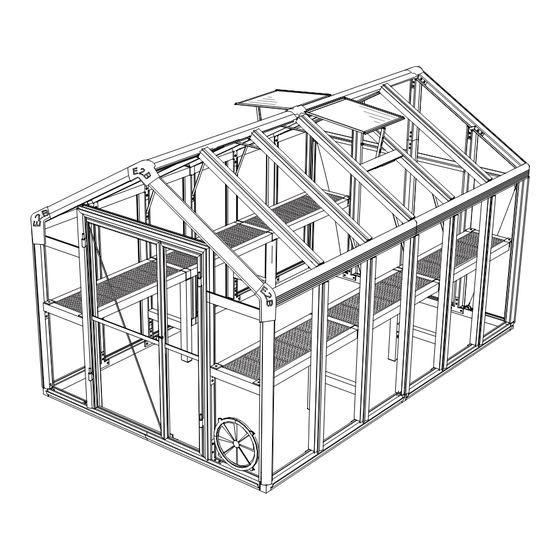
Introduction Thank you for purchasing your Easy2Build 8x12 Easy-Grow Greenhouse. This model features two roof vents and a circular air vent to ensure proper ventilation. We have also included an automatic vent opener to help you maintain optimal temperature effortlessly. When properly assembled and maintained, this greenhouse will provide years of enjoyment. -
Page 4: Table Of Contents
Safety Advice Table of Contents The greenhouse must be positioned and fixed on a flat level Introduction ......... surface. Safety Advice ........Dispose of all plastic bags safely. Keep them out of the reach General Order of Assembly .... of small children. List of Parts ........... -
Page 5: List Of Parts
List of Parts The greenhouse is shipped in three cartons. These cartons are heavy. Be careful when lifting them. Wear proper safety gear including work shoes, gloves and goggles. The parts are identified by removable stickers. Place all the parts for each step in staging areas, checking that you have all parts as you go. If any parts are missing or damaged, contact STC customer service before beginning assembly: Customer Service: (877) 407-9100 ext. - Page 6 Panel Connector Step 1 Step 4 Step 3 Steps 1,3 Step 3 Steps 1,3 Step 12 Step 12 Steps 1,3 Step 1 Steps 1,3 Step 1 Step 1 Step 1 Step 3 Step 3 Step 3 Step 4 Step 12 Step 12 Step 8 Step 12...
- Page 7 Trim Plate Bracing Parts Steps 1,3,9 L09C Step 14 Step 9 Steps 1,3 L09D Step 14 Steps 1,3,9 hex key J02L Step 14 Step 8 J02R Step 14 Step 14 Step 14 L15B Step 2 rubber 125.5M Steps 13,15 J01C stripping Shelf Trays Anchor Clip and Peg...
-
Page 8: Assemble Back
Assemble Back Place all the parts for the back face on a level surface. Make sure the pieces are in the correct positions before assembling. Carefully follow the order of assembly to ensure an easy installation. Wear proper safety gear including work shoes, gloves and goggles. The back is assembled with the outside face to the ground. - Page 9 1.3A Attach profiles L02B and L03C to profile L04F by sliding the long sides of connector S01 into channels lining up last hole in S01 with holes in profile L04F. Attach profiles L03D and L02A to profile L04F by sliding the long side of connector S01 into profile channels lining up last hole of S01 with holes in L04F.
- Page 10 1.4A Slide connector L16 inside profiles L03L and L03K. The two end holes on each side of connector L16 line up with the two holes on each profile. 1.4B Secure with four S02 screws. L03L L03L L03K Profile Connector #L03K #L16 #L03L #S02...
- Page 11 1.6A Slide connector L16 inside profiles L01I and L01J. 1.6B Line up the outside holes on L16 with second hole on profiles L01I and L01J. Secure with two S02 screws. L01I L01I L01J L01J NOTE: ALL VIEWS ARE FROM INSIDE Profile Connector #L01I...
- Page 12 1.7A Carefully line up connector S04 with profile L02B and connector S05 with profile L02A. Slide profiles L01I and L01J half way into place. Continue sliding until connectors S04 and S05 click securely into profiles. NOTE: ALL VIEWS ARE FROM INSIDE. L03L 1.7B Line up holes on connectors S08 with holes in...
- Page 13 1.9A Remove protective plastic from both sides of panels Y1, Y16, Y17 and Y18. Place side to face toward the sun facing down. Fit panels Y1 and Y16 into bottom channel of profiles L05A and L05H. L05A L05H L05H L05A Remove protective plastic from EACH side of poly carbonate panels before installing.
- Page 14 1.10 Slide hex nut S14 and hex bolts S13 into U-cutout in both sides of profiles L03C, L03D and L03K. Tighten securely to hold in place. NOTE: ALL VIEWS ARE FROM INSIDE. 1.11A Slide profiles L02I and L02J into connectors S09, S10 and S12 until they click into place.
- Page 15 1.11B Slide connectors S09 and S10 half way into profiles L02A and L02B. Continue sliding together making sure panels Y17 and Y18 fit into V-channels of profiles L02I and L02J. Connectors click securely into profiles. L02B Connectors S09 and S10 CLICK into place. L02A There is only one way to properly fasten connectors into profiles.
-
Page 16: Step
1.13A Insert long side of cable connector S06 at an angle into profile channel L02B with HOOK FACING UP. Slide connector to other side of channel. Use hex key to securely tighten and hold in place. L02B L04F L04F L02A L01I L01J 1.13B... -
Page 17: Assemble Doors
Assemble Doors Place all the parts for both doors on a level surface. Make sure the pieces are in the correct positions before assembling. Carefully follow the order of assembly to ensure an easy installation. Wear proper safety gear including work shoes, gloves and goggles. Both doors are assembled with the outside face to the ground. -
Page 18: Step
2.4A Slide hex nuts and bolts into U-cutout in side of profiles L13B and L13C. Tighten securely to hold in place. NOTE: The holes at the top of profile L13B and the bottom left corner of profile L13E will be secured in Step 2.5. 2.4B Secure connectors with six S02 screws. - Page 19 2.6A Open door handle kit and remove parts. Slide pin S29 through handle S30, washer S31and hole in profile L13C into washer S31. 2.6B Slide washer S32 into groove on pin S29 to hold securely in place. L13C L13C 2.6C Hook one side of spring S33 into hole on handle S30.
- Page 20 2.8B Place door profiles L13D, L13F, L13G and L13H next to connectors S28 around Y26 panels as shown. Slide connectors into profiles. Make sure panels and profile L05F fit into V-channels of each profile. L13G L13F L05F L13H 2.8C L13D Secure connectors with eight S02 screws.
-
Page 21: Assemble Front
Assemble Front Place all the parts for the front face on a level surface. Make sure the pieces are in the correct positions before assembling. Carefully follow the order of assembly to ensure an easy installation. Wear proper safety gear including work shoes, gloves and goggles. The front is assembled with the outside face to the ground. -
Page 22: S17L
3.2A Slide profiles L06J into L06A and L06K using connectors S28. S28 connectors do not snap into place. L06J L06K L06J S17L L06A S17R 3.2B Place connectors S17L and S17R on corners matching up bottom two holes with holes in profiles L06K L06A, L06J and L06K as shown. - Page 23 3.4A Slide profiles L02K and L02L into connectors S09, S18 and S10 until they click into place. Connectors S09, S10 and S18 CLICK into place. L02L L02K L02K L02L 26.5” (676 mm) 26.5” (676 mm) IMPORTANT: The holes are not at the midpoint of the profiles. Arrange profile so the 26.5”...
- Page 24 3.5A Slide connectors S09 and S10 half way into profiles L02A and L02B. Continue sliding together making sure panel Y20 fits into V-channels of profiles L02L and L02K. Connectors S17L and S17R L02K rest in channels of L02L and L02L L02K.
- Page 25 3.6A Remove protective plastic from both sides of panels Y5, Y6 and Y19. Place side to face toward the sun facing the down. Fit panels Y19 into top channels of L05C. IMPORTANT: Make sure to assemble a right and left side. L05C L05C L05C...
- Page 26 3.7B 3.7A Secure with two S02 screws. Line up connector S08C with holes on profiles L01K as shown. L01K L01K S08C 3.7C Slide connector L16 inside profiles L01K and L01L. 3.7D Line up outside holes on connector L16 with holes on profiles L01L and L01K.
- Page 27 3.9A As you slide bottom profiles L01L and L01K half way into place, carefully line up S01 connectors with channels on profiles L06K and L06A and S04 and S05 connectors with profiles L02B and L02A. Continue sliding, making sure panels Y6 and Y5 fit into V-channels. Snap connectors S04 and S05 securely into profiles.
-
Page 28: Step
3.10A Insert long side of cable connector S06 at an angle into profile channel L02B with HOOK FACING UP. Slide connector to other side of channel. Use hex key to securely tighten and hold in place. L02A L06A L06K L02B L01L NOTE: ALL VIEWS ARE FROM INSIDE. -
Page 29: Assemble Sides
Assemble Sides Place all the parts for the sides on a level surface. Make sure the pieces are in the correct positions before assembling. Carefully follow the order of assembly to ensure an easy installation. Wear proper safety gear including work shoes, gloves and goggles. You are assembling both sides in the following steps. - Page 30 Slide connector S39 into profile L04D until it snaps into place. Repeat to make four sets. L04D Connector Connector S39 CLICKS into place. #S39 There is only one way to properly fasten connectors into profiles. Line up parts first to ensure correct placement. Slide connectors until they CLICK securely into profile.
- Page 31 4.6A Connect profile L04D by sliding connector S39 4.6B into profile L04B until it snaps in place. Slide Secure with S02 screw. Repeat to connector S01 into channel of L04C. make four sets. Connector S39 CLICKS into place. L03V L04B L04C Screw #S02...
- Page 32 4.8A Line up the four profiles L03B so the holes are at the same position. Slide long side of connectors S20 and S08 into channel of profile, lining up holes as shown. 4.8B Secure with three S02 screws. Repeat to make four sets. L03B L03B Profile...
- Page 33 4.10A Place profiles L03B and L03V onto profiles L07D and L01D. Line up holes as shown. 4.10B Secure with six S02 screws. Repeat to make two sets. L07D L07D L07D L03B L03V L07D L03V L03V L03B L03B L01D L01D L01D Profile Profile Screw...
-
Page 34: Step
4.12 Carefully slide sections together as shown. We recommend using two people for this step. Repeat to make two sets. There is only one way to properly fasten connectors into profiles. Line up parts first to ensure correct placement. Slide connectors until they CLICK securely into profile. -
Page 35: Prepare Shelves
Prepare Shelves Place all the parts for the shelves on a level surface. Make sure the pieces are in the correct positions before assembling. Carefully follow the order of assembly to ensure an easy installation. Wear proper safety gear including work shoes, gloves and goggles. 5.1A Line up the shelf profiles so the holes are at the same position. -
Page 36: Connect Sides To Back
Connect Sides to Back With the outside facing a wall, carefully stand back up and lean against the wall. Stand each side up and place next to the back. Both sides are identical until the shelf profiles are connected. Make certain that positions of profiles L07A and L07B match the diagrams before connecting. - Page 37 6.2A Set up the other side facing inside with profile L07D L07D next to back. Slide shelf profile L14A into connector S03 until it clicks into place. Slide shelf profile L14C into connector S39 until it clicks into place. L14A L14A L14C L14C...
-
Page 38: Connect Sides To Front
Connect Sides to Front Keep the structure as is, with the back against the wall until you finish this step. This will make it easier to keep the angles square. Slide shelf profile L14A into connector S03 on the left side until it clicks into place. - Page 39 7.2A Lift front from inside and rest it next to sides. Line up connector S10 with profile L07D, connector S09 with profile L07C and connectors S04 and S05 with profiles L01D. L07D L14A L07C L14B L01D 7.2B Carefully pull the front until all connectors are half way inside each profile. Make sure connector S37 attached to shelf profiles rest on top of profile L04A.
- Page 40 7.3A Slide shelf profile L14C at a slight angle so one end slides half way into connector S39 and the other side with connector S37 rests on top of profile L04A. Continue to slide until profile clicks into connector S39. Connector S39 CLICKS into place.
-
Page 41: Assemble And Connect Gables
Assemble and Connect Gables Place all the parts for the gables on a level surface. Make sure the pieces are in the correct positions before assembling. Please carefully follow the order of assembly to ensure an easy installation. Wear proper safety gear including shoes, gloves and goggles. 8.1A Line up gable profiles with four S22 connectors as shown. - Page 42 From the inside of the greenhouse, use two people to carefully lower center gable onto frame. Line up and slide profiles L03N and L03Q into connectors S19 until they click securely into place. Connectors S19 CLICK into place. L03N L03Q L03N L03Q IMPORTANT: U-shaped cutouts on...
- Page 43 8.5A One of the L02H profiles has been shipped with L08A and L08B profiles installed as shown below. L02H L08A L08B Profile Profile #L08A #L02H #L08B 8.6A Using a small step ladder inside the greenhouse, carefully slide profile L02H with L08A and L08B connected into back connector S12 at a slight angle.
- Page 44 8.7A 8.7B From inside of greenhouse secure S20 connectors Secure each S22 connector to to gable profiles L03M, L03N, L03Q, L03R, L03S and profiles L02H with one S02 screw. L03U with two S02 screws. L02H L03S L03R VIEWS FROM INSIDE. Screw #S02 VIEWS FROM INSIDE.
-
Page 45: Brace Sides
Brace Sides Place all the parts for bracing the sides on a level surface. Make sure the pieces are in the correct positions before assembling. Please carefully follow the order of assembly to ensure an easy installation. Wear proper safety gear including shoes, gloves and goggles. 9.1A From the inside of the greenhouse, insert long side of cable connector S06 into profile channel L07C with hook facing the front. - Page 46 9.3A From the inside of the greenhouse, insert long side of cable connector S06 into channel of profile L07D with hook facing the back. Slide connector to other side of channel. Use hex key to securely tighten and hold in place. L07D L02A L02A...
-
Page 47: Assemble And Install Roof Vents
Assemble and Install Roof Vents Place all the parts for both roof vents and handles on a level surface. Make sure the pieces are in the correct positions before assembling. Carefully follow the order of assembly to ensure an easy installation. Wear proper safety gear including work shoes, gloves and goggles. - Page 48 10.4B 10.4A Fit piston rod connected to arm Unpack contents of Auto Vent Opener. Screw assembly B into the end of the cylinder. knob partially into threaded end of cylinder. Do NOT tighten. Turn cylinder so the holes next adjusting knob cylinder to the adjusting knob are visible.
- Page 49 10.7 Repeat step 10.6 to install profile L05G on the other side of the greenhouse. With the nuts and bolts are facing the inside, secure profile L05G to profiles L03N and L03S. L03S L03N L05G L03N L05G L03S L03S L05G L05G VIEWS FROM INSIDE.
- Page 50 10.9A Stand on a small step ladder inside the greenhouse. Install second roof vent to the left side of the greenhouse. Slide profile L11A into profile L08B from the back of the greenhouse towards the front. 10.9B L11A Continue to slide vent past the end of L08B profile L08B until the hole in the other end is visible.
-
Page 51: Install Circular Vent
Install Circular Vent Place all the parts for circular vent on a level surface. Make sure the pieces are in the correct positions before assembling. Carefully follow the order of assembly to ensure an easy installation. Wear proper safety gear including work shoes, gloves and goggles. 11.1A Open box containing the parts for circular vent. -
Page 52: Install Side And Roof Panels
Install Side and Roof Panels Place all side and roof panels on a level surface. Make sure the pieces are in the correct positions before assembling. Carefully follow the order of assembly to ensure an easy installation. Wear proper safety gear including work shoes, gloves and goggles. 12.1 Remove protective plastic from both sides of panels Y9 and Y10. -
Page 53: Install Weather Stripping
Install Weather Stripping If you have been assembling your greenhouse in another place than it’s final position, we recommend you move the greenhouse before you begin these steps. Have at least one person help you carry it. NOTE: You will find a roll of 125.5 meters of black rubber weather stripping. -
Page 54: Install Trim Plates
Install Trim Plates Place the trim plates on a level surface. Make sure the pieces are in the correct positions before assembling. Carefully follow the order of assembly to ensure an easy installation. Wear proper safety gear including work shoes, gloves and goggles. 14.1 Remove the six hex nuts from the hex bolts attached to each L09C and L09D trim plate BEFORE installing. - Page 55 14.4A In the front of the greenhouse, slide plastic trim plates J02L, J02R, and J03 into connectors S09, S10 and S18 until they snap into place. On top of the greenhouse, snap trim plate J06 onto connector S21. The trim plates will cover the edges of the black rubber stripping installed in step 13.
-
Page 56: Weather Strip And Hang Doors
Weather Strip and Hang Doors The doors have been assembled in step 2. When hung, the bracing bar on the large door and the door locks on the small door are on the inside of the greenhouse. We recommend using two people to hang the doors. NOTE: You will use the remainder of the roll of 125.5 meters of black rubber weather stripping. -
Page 57: Secure To Ground
Secure to Ground IMPORTANT: The greenhouse must be firmly secured to the ground. Make sure the foundation is FLAT and LEVEL. Make sure the greenhouse is square. The two diagonal measurements inside the greenhouse should be identical. From the inside of the greenhouse, insert the S34 anchor clips into channels of side profile L01D at each corner and center of both sides. -
Page 58: Install Trays And Bin Holder
Install Trays and Bin Holder Place all the parts for the trays and bin holder on a level surface. Make sure the pieces are in the correct positions before assembling. Carefully follow the order of assembly to ensure an easy installation. Wear proper safety gear including work shoes, gloves and goggles. - Page 59 Notes:...
- Page 60 Systems Trading Corporation 8’ x 12’ Easy-Grow Greenhouse Assembly Instructions Please keep this manual in a safe place for reference. If you need any help or have missing or damaged parts, please contact us. Systems Trading Corporation 450 7th Avenue Suite 2809, New York, NY 10123 Customer Service: (877) 407-9100 ext 1 Email: customerservice@stcaustin.com...
Need help?
Do you have a question about the Easy2Build and is the answer not in the manual?
Questions and answers
ARE PANELS AVAILABLE FOR POSITIONS Y-9 AND Y-21
Yes, panels are available for positions Y-9 and Y-21 in the Systems Trading Corporation Easy2Build system.
This answer is automatically generated
How thick are the polycarbonate panels? Can we order replacement sheets? We had a recent hail storm that damaged all the roof panels. We have an 8x8 Easy2Build