Table of Contents
Advertisement
200 New Highway
Toll Free : 1-800-645-5516 In Metro NY : 631-957-8700
Fax : 631-957-9142 or 631-957-3880 Web: www.specotech.com
VIDEO SECURITY
INTERCOM SYSTEM
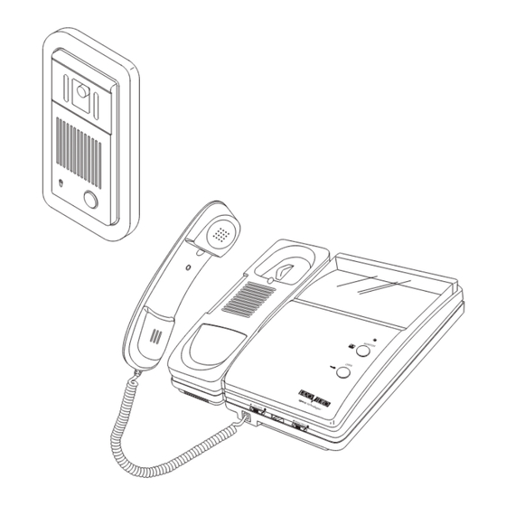
Complete with 1 Monitor and 1 Camera
Expandable up to 2 Monitors and 2 Cameras
INDOOR MONITOR
OUTDOOR CAMERA
(FLUSH MOUNT)
Amityville, N.Y. 11701
VDP-5000
Advertisement
Table of Contents

Subscribe to Our Youtube Channel
Summary of Contents for Pro Video VDP-5000
-
Page 1: Intercom System
VIDEO SECURITY INTERCOM SYSTEM Complete with 1 Monitor and 1 Camera Expandable up to 2 Monitors and 2 Cameras INDOOR MONITOR VDP-5000 OUTDOOR CAMERA (FLUSH MOUNT) 200 New Highway Amityville, N.Y. 11701 Toll Free : 1-800-645-5516 In Metro NY : 631-957-8700... -
Page 2: Important Safety Instructions
WARNING : TO PREVENT FIRE OR ELECTRIC SHOCK DO NOT EXPOSE THIS APPLIANCE TO RAIN OR MOISTURE CAUTION RISK OF ELECTRIC SHOCK DO NOT OPEN CAUTION : TO REDUCE THE RISK OF ELECTRIC SHOCK, DO NOT REMOVE COVER(OR BACK). NO USER SERVICEABLE PARTS INSIDE. REFER SERVICING TO QUALIFIED SERVICE PERSONNEL This symbol is intended to alert the user to the presence of uninsulated... - Page 3 Cleaning Unplug this product from the wall outlet before cleaning. Use a damp (not wet) cloth for cleaning. Do not clean the cabinet with liquid cleaners, aerosol cleaners, gasoline or other types of flammable fluids. Water and Moisture Do not use this product near water. For example : near a bath tub, wash bowl, kitchen sink, or laundry tub;...
- Page 4 Replacement Parts Use only replacement parts that are specified by the manufacturer or that have the same characteristics as the original part. Unauthorized substitutions may result in fire, electrical shock, or other hazards and void warranty. Safety Check Upon completion of any service or repairs to this product, ask the service technician to perform safety checks to determine that the product is in proper operating condition.
-
Page 5: Table Of Contents
INTRODUCTION Congratulations on the purchase of your new video intercom system! Please read these instructions carefully before installing your system and follow all of the directions to ensure proper installation. This instruction manual explains in simple steps how to install, use, and care for your new video doorphone system in homes, offices or businesses. -
Page 6: Parts Checklist
PARTS CHECKLIST Monitor ............................1 Handset............................1 Mounting Bracket .........................1 Mounting Screws for Bracket .......................2 Monitor Mounting Screw (to Bracket) ...................1 DC Adapter ..........................1 Figure 1 Camera(VDP-C5F) Camera Wall Bracket Mounting Screw - T4 18mm(ZnW) - M3 36mm(Ni) - M3 34mm(Bk) Camera Fixing Screw(M4 15) Screw cover Figure 2... -
Page 7: Features
FEATURES 7 8 9 by CSI/SPECO Figure 3 1. Handset Releases the door to let your visitors come Lift to communicate with caller. in after viewing them(You must supply an 2. Speaker electronic door release for this function to Chime tone sounds when callers push the work.) -
Page 8: Features
FEATURES Front View Back View Figure 5 FRONT PANEL INFRARED LED : Allows for the viewing of caller at any illumination CCD CAMERA LENS LENS WINDOW SPEAKER : Provide high quality audio to a caller. CALL BUTTON MICROPHONE SCREW COVER LEVER FOR ANGLE ADJUSTMENT TERMINAL DOOR RELEASE CABLE... -
Page 9: Installation
INSTALLATION MONITOR Monitor Handset 1. Connect the handset and cord to the Monitor ¿ Ω ¿ ¸ π ‡ ∑ Æ ≤®¡ ø ¯ ± ‚ ƒ—¡ ¸ ¸ Jack. 2. Determine the position of the monitor display. Jack Plug The standard position is at eye level. -
Page 10: Installation
INSTALLATION CAMERA 1. Install the recessed camera box into the wall, secure properly. 2. Remove the front panel from main unit. 3. Place the main unit and the front panel into the box using the two tamperproof screws. Tighten with wrench supplied. Power Source T4 18 Door... -
Page 11: Wiring Diagram
WIRING DIAGRAM VDP-C5F CAMERA FOR VDP-5000 1 Monitor & 2 Cameras Figure 10 Use of color coded cable is recommended for proper wiring connection. 2 Monitors & 2 Cameras Figure 11... -
Page 12: Operation
OPERATION Turn the power switch ON. Use the side buttons for volume and brightness controls. Buzz Call Button: 1. A visitor presses the Call button on the Camera. A tone is heard at the monitor. 2. The caller then talks handsfree after you answer the call. Monitor Station: 1. -
Page 13: Trouble Shooting Guide
Optimal Working Temperature : +14 F to + 104 F. Weight : 3.3 Ibs. Dimensions : 9 (H) 7 (W) 2 (D). Adapter Input AC 120V ; 60Hz ; 0.35A DC 17.0V - . .. 1.3A Adapter Output VDP-5000 Printed in Korea...
Need help?
Do you have a question about the VDP-5000 and is the answer not in the manual?
Questions and answers