Table of Contents
Advertisement
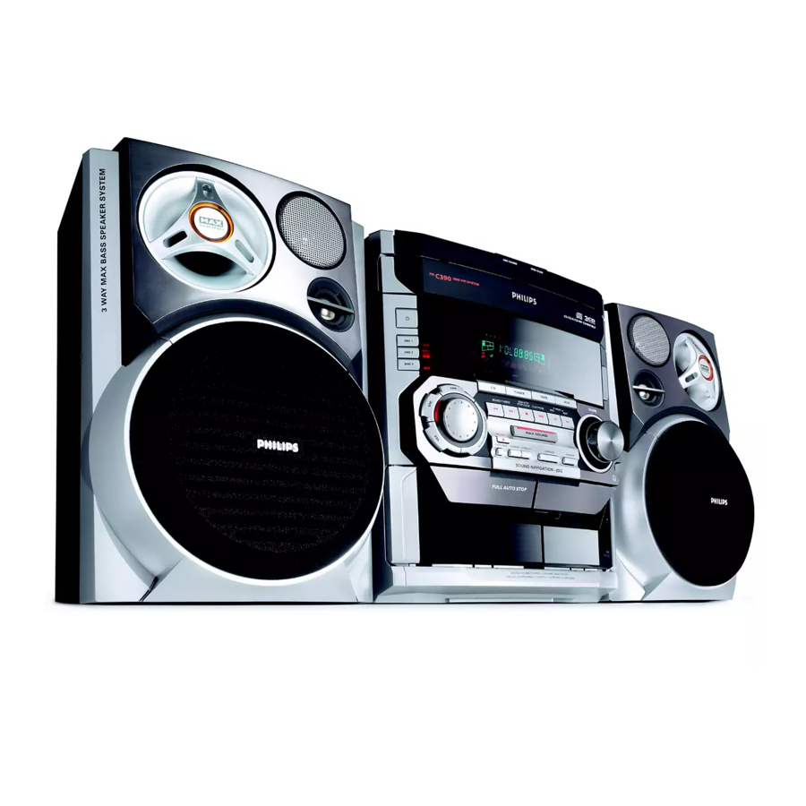
Mini System
Service
Service
Service
Service
Service
Service Manual
©
Copyright 2001 Philips Consumer Electronics B.V. Eindhoven, The Netherlands
All rights reserved. No part of this publication may be reproduced, stored in a retrieval system or
transmitted, in any form or by any means, electronic, mechanical, photocopying, or otherwise
without the prior permission of Philips.
Published by SL 0251 Service Audio
Version 1.0
TABLE OF CONTENTS
Location Of Pc Boards & Version variations ................ 1-2
Technical Specifications ............................................. 1-3
Measurement Setup .................................................... 1-4
Service Aids, Safety Instruction, etc. .......................... 1-5
Preparations & Controls ............................................. 1-7
Maintenance & Troubleshooting .............................. 1-10
Disassembly Instructions & Service positions .............. 2
Service Test Programs & DEMO Mode ......................... 3
Set Block Diagram ......................................................... 4
Set Wiring Diagram ........................................................ 5
Front Board .................................................................... 6
Tuner Board: Systems Non-Cenelec ....................... 7A
Systems Cenelec ............................... 7B
Etf7 Tape Module ........................................................ 9
3CDC-LLC-MB Module ................................................ 10
Power 2001 Module (30-70W Version) ....................... 11
Af9 Board .................................................................... 12
Set Mechanical Exploded view & parts list ................. 13
Printed in The Netherlands
Subject to modification
FW-C390/
21/21M/22/30/33/34
COMPACT
DIGITAL AUDIO
Page
CLASS 1
LASER PRODUCT
GB
3140 785 32360
Advertisement
Table of Contents

Related Manuals for Philips FW-C390


Summary of Contents for Philips FW-C390
- Page 1 LASER PRODUCT © Copyright 2001 Philips Consumer Electronics B.V. Eindhoven, The Netherlands All rights reserved. No part of this publication may be reproduced, stored in a retrieval system or transmitted, in any form or by any means, electronic, mechanical, photocopying, or otherwise without the prior permission of Philips.
- Page 2 LOCATION OF PC BOARDS MAINS SOCKET BOARD POWER BOARD HEADPHONE BOARD VERSION VARIATIONS: Type /Versions: FW-C390 /21M Features & Board in used: Karaoke News Rotary Encoder (volume control) Jog Shuttle Voltage Selector Aux Input Digital Output Headphone Socket Line Output...
- Page 3 SPECIFICATIONS GENERAL: AMPLIFIER: Mains voltage : 110-127V/220-240V Switchable for /21/21M 230V for /22/30/33/34 Output power (6Ω, 1 kHz, 10% THD) : 2 x 60W Mains frequency : 50/60Hz Frequency response within -3dB : 60Hz-16kHz Power consumption : < 1W at ECO Standby (FTD off) Dynamic Bass Boost : DBB OFF, DBB 1, DBB 2, DBB 3 <...
-
Page 4: Measurement Setup
MEASUREMENT SETUP Tuner FM Bandpass LF Voltmeter 250Hz-15kHz e.g. PM2534 e.g. 7122 707 48001 RF Generator e.g. PM5326 S/N and distortion meter e.g. Sound Technology ST1700B Use a bandpass filter to eliminate hum (50Hz, 100Hz) and disturbance from the pilottone (19kHz, 38kHz). Tuner AM (MW,LW) Bandpass LF Voltmeter... -
Page 5: Service Aids
SERVICE AIDS ESD Equipment: Service Tools: Anti-static table mat - large 1200x650x1.25mm ... 4822 466 Universal Torx driver holder ......4822 395 91019 10953 Torx bit T10 150mm ........4822 395 50456 Anti-static table mat - small 600x650x1.25mm ..4822 466 Torx driver set T6 - T20 ...... -
Page 6: Laser Product
WAARSCHUWING WARNING Alle IC’s en vele andere halfgeleiders zijn All ICs and many other semi-conductors are gevoelig voor electrostatische ontladingen susceptible to electrostatic discharges (ESD). (ESD). Careless handling during repair can reduce life Onzorgvuldig behandelen tijdens reparatie kan drastically. de levensduur drastisch doen verminderen. When repairing, make sure that you are Zorg ervoor dat u tijdens reparatie via een connected with the same potential as the mass... - Page 10 1-10 MAINTENANCE AND TROUBLESHOOTING...
- Page 11 DISMANTLING INSTRUCTIONS Dismantling of the CDC Module and Front Panel Dismantling of the Cassette Cover 4) Remove the Cover Tray CDC (pos 106) as indicated. 2. Twist screw driver 3. Lift up and out 1. Place screw driver (flat side) between the cassette cover &...
- Page 12 Dismantling of the Front Board Dismantling of Rear Portion 1) Remove 1 screw C as indicated to loosen the Headphone 1) Remove 3 screws J and uncatch M1 as indicated to Board (pos 1101-C). loosen the AF Board (pos 1102). 2) For set without Karaoke : 2) Remove 3 screws K and uncatch M2 as indicated to Remove 11 screws D and 2 screws E as indicated to...
- Page 13 Repair Hints 3) During repair it is possible to disconnect the Tuner board Service pos C Picture 3 and CDC Module completely unless the fault is sus- pected to be in that area. This will not affect the performance of the rest of the set. 4) Due to the short flex cable wires in the ETF Module, the pc board should be disconnected and reconnected on the reverse side of the tape mechanism to keep it...
- Page 14 SERVICE TEST PROGRAM DEMO Mode To start service test program hold P & AUX depressed while ACTION plugging in the mains cord Hold the 9 button down for 5 seconds during the DEMO display, To Switch off the set will confirm with "DEMO OFF" and switch to Standby. Hold the 9 button down for 5 seconds during Standby, DEMO To Switch on S refers to Service Mode.
- Page 15 SET BLOCK DIAGRAM SIMPLE KARAOKE -CMOS (-9V) SA BUFFER -Vkk -CMOS 500mV +12A +12A +12M 76dBA 16dB SWITCH -Vkk +9.1V 250mV HEADPHONE MIC DET -6dB TRACK 3CDC-L2C 650mV LOW_PWR_SUP +5V6_CON 78dBA 3.2dB +9.1V CONTROL HP DET 100mV HP DET FM (67.5 kHz) +12A AM (80% MOD) TDA7468...
- Page 16 SET WIRING DIAGRAM 1805 CDC-L2C 1403 1440 FRONT CD_LEFT 1400 CD CHANGER GND_A KEY1 CDC KEYS CD_RIGHT (1101) KEY2 FFC AD +5V_CD GND_D (1101) 220mm GND_M 3CDC-L2C FFC SIDE FFC SIDE +12V_D SW_INFO SHR_STR (1105) SH_CLK SICL SH_DATA SILD GND_D_CD PORE GND_D 1402...
- Page 17 FTD DISPLAY PIN CONNECTIONS MUTE 1 2 3 NEWS TITLE FM MW FRONT BOARD (10G-13G) TABLE OF CONTENTS FTD pin connection ............6-1 Variation Table ..............6-2 (14G) (1G-8G) (9G) Key-CDC part - Layout & Circuit diagram ....... 6-2 Front part - Circuit diagram ..........6-3 Front part - Component layout ........
- Page 18 VARIATION TABLE KEY-CDC PART - CIRCUIT DIAGRAM Item No / Features FW-C390/30/37 FW-C390/21/21M/33 FW-C390/22/34 RDS / News 1440 A1 1441 A2 1442 A2 Simple Karaoke Mic Detect 1409 1424 1425 1427 1441 1442 1437 1440 3486 P04x DISC CHANGE OPEN/CLOSE...
- Page 19 FRONT PART - CIRCUIT DIAGRAM 1400 A9 3445 G6 4522 D4 1401 C1 3446 A9 5400 B4 1402 G1 3447 A8 5401 A16 1403 B3 3448 C8 5402 C11 1404 G16 3449 C9 5403 I12 1405 D13 3450 D6 5404 L13 6400 1406 D14 3451 C6...
- Page 20 FRONT PART - COMPONENT LAYOUT This assembly drawing shows a summary of all possible versions. For components used in a specific version see schematic diagram and respective parts list. 3139 113 3442 pt 2a dd wk147...
- Page 21 FRONT PART - CHIP LAYOUT This assembly drawing shows a summary of all possible versions. For components used in a specific version see schematic diagram and respective parts list. 3139 113 3442 pt 2a dd wk147...
- Page 22 HEADPHONE PART - CIRCUIT DIAGRAM KARAOKE PART - COMPONENT & CHIP LAYOUTS 1600 C1 1601 B3 This assembly drawing shows a summary of all possible versions. For 1602 A3 components used in a specific version see schematic diagram and 2600 A2 9600 respective parts list.
- Page 23 KARAOKE PART - CIRCUIT DIAGRAM 30 D9 1802 C2 2802 B5 2805 B5 2808 E3 2811 D6 2814 E7 2817 D8 3800 A2 3803 B3 3806 C4 3809 B6 3812 B8 3815 D5 3818 E6 3821 D8 5800 B2 7800 B4 7803 E6 9800 A5 1800 C1...
- Page 24 ELECTRICAL PARTS LIST - FRONT BOARD ELECTRICAL PARTS LIST - FRONT BOARD MISCELLANEOUS 2410 4822 126 14305 100nF 10% 16V 2600 4822 126 14494 22nF 10% 25V 3443 4822 051 30103 10k 5% 0,062W 1400 3139 110 52900 FTD Display HNA-14MS06T 1401 4822 265 11545 Flex Socket 19 Pin Hort.
- Page 25 ELECTRICAL PARTS LIST - FRONT BOARD ELECTRICAL PARTS LIST - FRONT BOARD RESISTORS 3498 4822 051 30102 1k 5% 0,062W 3550 4822 051 30561 560R 5% 0,062W 3808 4822 117 12968 820R 5% 0,62W 4462 4822 051 30008 0R Jumper 0603 3499 4822 050 21003 10k 1% 0,6W...
- Page 26 6-10 6-10 ELECTRICAL PARTS LIST - FRONT BOARD ELECTRICAL PARTS LIST - FRONT BOARD RESISTORS 4518 4822 051 30008 0R Jumper 0603 6401 4822 130 31878 1N4003G 7410 4822 130 60511 BC847B 4519 4822 051 30008 0R Jumper 0603 6402 4822 130 30621 1N4148 7411...
- Page 27 7A-1 7A-1 BLOCK DIAGRAM TUNER BOARD ECO 6 Systems Vcc1 buffer ampl. Stab Stab Discriminator FM-RF FM-IF 1 FM-IF 2 (MPX) Vcc2 1101 Loop (1102) LF filter 10,7 MHz 10,7 MHz 10,7 MHz 1120 left left Stereo right right Det. Decoder Frontend Mixer...
- Page 28 7A-2 7A-2 1101 A1 1102 B1 1103 F2 1120 E14 1130 A2 TUNER BOARD ECO6 1131 B2 / SYSTEMS NON CENELEC 1132 G13 2101 B3 VERSION PROGRAMMING COMPONENTS 2102 B1 1101 2103 C7 2105 2104 B3 AM-IF1 1130 2105 A2 100n 5111 450kHz...
- Page 29 7A-3 7A-3 1101 A6 1120 A4 1132 A5 2128 C4 2138 C2 3142 D2 5110 B3 5114 A2 5123 D5 7112 C1 9104 B5 9107 D4 TUNER ADJUSTMENT TABLE ( ECO6 FM/MW- and FM/MW/LW - versions with AM-frame aerial ) 1102 B6 1130 B5 2106 C5...
- Page 30 7A-4 7A-4 Electrical Partslist ECO6 SYSTEMS NON CENELEC MISCELLANEOUS RESISTORS ––––––––––––––––––––––––––––––––––––––––––––––––––––– ––––––––––––––––––––––––––––––––––––––––––––––––––––– 1101 2422 015 19376 SOCKET 2P CLICKFIT 3143 © 4822 051 20223 22kΩ 0,1W USA only RDS only 1102 4822 267 10283 SOCKET COAX, IEC 75Ω 3144 © 4822 051 10102 1kΩ...
- Page 31 7B-1 7B-1 BLOCK DIAGRAM ECO6 Tuner Board SYSTEMS CENELEC version: TABLE OF CONTENTS Blockdiagram ..............7B-1 Schematic Diagram ............7B-2 Component Layout............7B-3 Adjustment table .............7B-3 Electrical Partslist ............7B-4...
- Page 32 7B-2 7B-2 1101 A2 5121 E11 1102 B1 5122 H5 1103 E2 5123 G5 1110 B2 6105-1 E4 VERSION PROGRAMMING COMPONENTS 1120 E14 6105-2 G6 TUNER BOARD ECO6 1130 A2 6106 D4 / SYSTEMS-CENELEC 1131 C2 6107 G13 VERSION AM-IF1 1132 F13 6120 C13 6120...
- Page 33 7B-3 7B-3 1101 B5 1110 B4 1131 C5 2107 B3 2133 C1 2162 A4 5102 C4 5110 A2 5114 A2 5121 B2 7104 C4 9101 A2 9104 B1 9107 B4 9110 A4 TUNER ADJUSTMENT TABLE ( ECO6 Cenelec FM/MW - and FM/MW/LW - versions with AM-frame aerial ) 1102 B5 1120 A4 1132 A4...
- Page 34 7B-4 7B-4 Electrical Partslist ECO6 SYSTEMS CENELEC MISCELLANEOUS RESISTORS DIODES ––––––––––––––––––––––––––––––––––––––––––––––––––––– ––––––––––––––––––––––––––––––––––––––––––––––––––––– ––––––––––––––––––––––––––––––––––––––––––––––––––––– 1101 2422 015 19376 SOCKET CLICKFIT 2P 3128 © 4822 117 11449 2,2kΩ 0,1W 6105 © 4822 130 83075 HN1V02H USA only LW only 1102 4822 267 10283 SOCKET COAX, IEC 75Ω...
- Page 35 Tapedeck wiring (Double deck) TO ETF BOARD CONNECTOR 1770 (ND) 14P CONNECTOR 1740 (DB) 14P CRO2* CRO2* * Not for Ferro version ETF7 TAPE MODULE (Non-Dolby Version) MODE TAPE DECK MOTOR Mechanism B Mechanism A TO ETF BOARD TO ETF BOARD CONNECTOR 1730 (3P) CONNECTOR 1710 (ND) 5P CONNECTOR 1720 (DB) 6P...
- Page 36 BLOCK DIAGRAM Line-In ATTEN 7710 7720 PB Out 9792 # Playback PRE-AMPLIFIER SOURCE SEL ATTEN Head AN7318S HEF4952BT For Dolby version only ALCEN 1A0 1A1 1A2 PB In PB Out 7630 Rec current REC Out DOLBY B NR Rec/Pb 7740 Rec In CXA1101M Head...
- Page 37 Brief introduction General 13. Motor Speed (For FR versions only) Playback Mode Signal from the playback head Deck A or Deck B is selected and fed through by the Mode Selector IC7710 (HEF4952BT). During High speed dubbing, a feedback signal from the uP through pin 03 of the IC7610 (HEF4094BT) will trigger the transistors 7622 (BC847B) and 7616 (BC857B) to cause a change in the voltage level between High and Low, thus changing The signal is amplified by amplifier IC7720 (AN7323S) before feeding to the IC7740 (HEF4952BT) and out to the AF Board via connector 1701.
- Page 38 CONNECTORS ASSIGNMENTS: CONNECTOR 1701 INTERCONNECTION TO AF BOARD CONNECTOR 1740 DECK A & B CONTROL INTERFACE (For Dolby B NR version only) REC REW Record tab protection status switch (reverse) [open=on: close=off] REC-L Record input left REC-R Record input right CrO2 B Chrome tape detection switch deck B [open=Cr: close=Fe]...
- Page 39 TAPE MECHANISM ELECTRONICS TAPE ADJUSTMENT & CHECK TABLE ADJUST TEST RECORDER MEASURE READ ON CASSETTE MODE with B Photo Sensor 1. B Rec Switch (REV) Rec-R ADJUST MOTOR SPEED 2. B CrO2 Switch CrO2* PLAY B 3620 3150Hz +/- 0.5% SBC420 frequency NORMAL SPEED...
- Page 40 COMPONENT LAYOUT CHIP LAYOUT Some location on this board is prepared for both 0603 & 0805 SMDs footprint, 3139 113 3409 pt2 dd wk0042 in such locations 0603 SMDs may be substituted. 3139 113 3409 pt2 dd wk0042...
- Page 41 ANALOG CIRCUIT 1701 F9 2705 A2 2712 B6 2719 C5 2726 D4 2735 B3 2745 F5 2765 B4 2785 F1 3705 A4 3712 B4 3719 C6 3726 D5 3733 A2 3744 F8 3753 F5 3760 A7 3767 A7 3774 E3 3781 D2 4794 C6 6774 D3...
- Page 42 SERVO CONTROL CIRCUIT 1702 A7 1760 B8 2622 D2 2625 E4 3601 B2 3604 C2 3607 C6 3610 D6 3613 B2 3618 A4 3622 A4 3625 B3 3630 A6 3676 C5 3680 C5 3687 D2 4785 D2 6612 B6 7612 A6 7616 A4 7620 B6 7624 D6...
- Page 43 TAPE MECHANISM - MOTOR EXPLODED VIEW TAPE MODULE EXPLODED VIEW 4822 361 11055 Motor Assembly 1 3139 118 77130 Autoreverse Mech. CWE44FR01 Screw M2,6 x 5 1 3139 118 77140 Non-Autoreverse Mech. CWE44FF02 Chrome/Ferro Screw M2 x 5 1 3139 118 77950 Non-Autoreverse Mech.
- Page 44 9-10 9-10 TAPE MECHANISM A - PLAY MECHANICAL PARTS - PLAY MECHANISM 9965 000 02313 Play Head (Non-Autoreverse deck) 9965 000 02321 Play Head (Autoreverse deck) 4822 402 10972 Pinch Arm Assembly R 9965 000 02314 Coil Assembly 9965 000 06443 Cam Gear 4822 528 11209 Flywheel Assembly RV...
- Page 45 9-11 9-11 TAPE MECHANISM B - RECORD/PLAYBACK (Non-Autoreverse version) MECHANICAL PARTS - REC/PB MECHANISM 9965 000 02313 Play Head 9965 000 02600 Head, Erase 4822 402 10972 Pinch Arm Assembly R 9965 000 02314 Coil Assembly 9965 000 06443 Cam Gear 4822 528 11209 Flywheel Assembly RV 44-2...
- Page 46 9-12 9-12 TAPE MECHANISM B - RECORD/PLAYBACK (Autoreverse version) MECHANICAL PARTS - REC/PB MECHANISM 4822 402 10972 Pinch Arm Assembly R 9965 000 02314 Coil Assembly 9965 000 06443 Cam Gear 4822 528 11209 Flywheel Assembly RV 9965 000 02322 Belt AF 44-2 9965 000 02317...
- Page 47 9-13 9-13 ELECTRICAL PARTS LIST - ETF7 NON-DOLBY BOARD ELECTRICAL PARTS LIST - ETF7 NON-DOLBY BOARD MISCELLANEOUS 2738 482212614585 100nF 10% 50V 3685 482211652234 100k 5% 0,5W 3745 482205120332 3k3 5% 0,1W Autoreverse 1701 482226710953 Flex Socket 7pin Vert. 2741 482212611585 22nF +80/-20% 25V 3686 482211710837 100k 1% 0,1W...
- Page 48 9-14 9-14 ELECTRICAL PARTS LIST - ETF7 NON-DOLBY BOARD RESISTORS 4706 482205120008 0R Jumper 0805 6612 482213031878 1N4003G 4707 482205120008 0R Jumper 0805 6614 482213030621 1N4148 Autoreverse 4708 482205120008 0R Jumper 0805 6770 482213030621 1N4148 4709 482205120008 0R Jumper 0805 6771 482213030621 1N4148 4710 482205120008...
-
Page 49: Table Of Contents
10-1 3CDC-LLC-MCD1 (3 Disc Carousel Changer) Layout stage .3 TABLE OF CONTENTS Service Hints ..............10-2 Blockdiagram ..............10-5 Component Layout Main Board ........10-6 Circuit Diagram part1 ............10-7 Component Layout Main Board ........10-8 Circuit Diagram part2 ............10-9 Exploded View ..............10-10 Partslist ................10-12... -
Page 50: Service Hints
10-2 Service hints CAUTION CHARGED CAPACITORS ON THE SERVO BOARD MAY DAMAGE THE CD DRIVE ELECTRONICS WHEN CONNECTING A NEW CD MECHANISM. THAT´S WHY, BESIDES THE SAFETY MEASURES LIKE • SWITCH OFF POWER SUPPLY • ESD PROTECTION ADDITIONAL ACTIONS MUST BE TAKEN BY THE REPAIR TECHNICIAN. The following steps have to be done when replacing the CD mechanism: 1. - Page 51 10-3 Service hints Dismantling of Tray 1. Open the tray. 2. Release 2x catch as shown in fig. 2 and Detail A 3. Pull tray out. Detail A fig.2 Assembling of Tray 1. Turn Cam (pos. 48) clockwise to end position.
- Page 52 10-4 Service Position...
- Page 53 10-5 10-5 BLOCK DIAGRAM 3CDC-LLC-MCD1 CD MECHANISM MAINBOARD MCD-1 DISC 7806 7802 TDA7073A TURNTABLE FOCB+ MOTOR FOCUS MOTOR FOCB- RADIAL RADB+ MOTOR RADB- 7805 1805 7807 TDA7073A SIGNAL PROCESSOR CD LEFT SLEDGEB+ SLEDGE CD10 MOTOR SAA7324 (SAA7325) SLEDGEB- Active low pass Analog Audio Filter TDA1308...
- Page 54 10-6 10-6 Mapping Copperside Componentside 2800 E3 3741 C4 3889 C2 1800 F2 2801 D4 3742 C4 3890 H2 1801 C5 3CDC-LLC Copperside view 3CDC-LLC Componentside view 2802 E4 3743 C3 3891 H2 1805 A2 2803 D4 3744 B4 3892 C2 1810 C2 2805 D4 3746 B3...
- Page 55 10-7 10-7 1800 F1 2804 D4 2811 A9 2818 B11 2826 G12 2838 D8 2851 B11 2888 C4 3702 D3 3721 D6 3792 F8 3800 D8 3807 B9 3819 D14 3828 G11 3839 H6 3846 F5 3863 G13 3895 G12 7803-B D5 MP713 C9 MP743 D2...
- Page 56 10-8 10-8 Mapping Copperside Componentside 2800 E3 3741 C4 3889 C2 1800 F2 2801 D4 3742 C4 3890 H2 1801 C5 3CDC-LLC Copperside view 3CDC-LLC Componentside view 2802 E4 3743 C3 3891 H2 1805 A2 2803 D4 3744 B4 3892 C2 1810 C2 2805 D4 3746 B3...
- Page 57 10-9 10-9 1805 E15 2830 C9 2858 A9 2865 C4 2877 F11 3705 G4 3713 G8 3730 G2 3741 A7 3751 C7 3851 D7 3865 A10 3874 C13 3880 E6 3886 E7 3898 F7 4876 D13 6875 F7 7805-B A8 7876 G3 MP726 D8 MP804 G14...
- Page 58 10-10 10-10 EXPLODED VIEW (3CDC-LC M ODULE 45 5x MECHANICAL PARTS Loader → this page ––––––––––––––––––––––––––––––––––––––––––––––––––––– 3103 304 66500 DRAWER 3140 114 29070 PRESSURE RING-MCD1 3140 111 21270 METAL RING-MCD1 3103 304 66560 SUPPORT 4822 529 10386 RUBBER DAMPER CD DRIVE, REAR 4822 529 10387 RUBBER DAMPER CD DRIVE, FRONT 3103 304 06970...
- Page 59 10-11 Drawer bottom view Drawer top view spare part non spare part 3CDC-LC Drawer assy 1999 09 13...
- Page 60 10-12 ELECTRICAL PARTSLIST 3CDC-LLC-MCD1 MODULE –––––––––––––––––––––––––––––––––––––––––––––––––––––––––––––––––––––––––––––––––––––––––––––––––––––––––––––––––– MISCELLANEOUS CAPACITORS ––––––––––––––––––––––––––––––––––––––––––––––––––––– ––––––––––––––––––––––––––––––––––––––––––––––––––––– 3103 309 05350 CD DRIVE MCD1B 2860 4822 124 11947 10µF 4822 361 10753 CAROUSEL MOTOR 2861 4822 124 11947 10µF 4822 361 10753 TRAY MOTOR 2862 © 4822 126 13883 220pF 1800 2422 025 17389...
- Page 61 10-13 ELECTRICAL PARTSLIST 3CDC-LLC-MCD1 MODULE –––––––––––––––––––––––––––––––––––––––––––––––––––––––––––––––––––––––––––––––––––––––––––––––––––––––––––––––––– RESISTORS RESISTORS ––––––––––––––––––––––––––––––––––––––––––––––––––––– ––––––––––––––––––––––––––––––––––––––––––––––––––––– 3801 © 4822 051 30103 10kΩ 0,06W 3880 © 4822 051 30392 3,9kΩ 0,06W 3802 © 4822 051 51831 18kΩ 0,1W 3881 © 4822 117 13632 100kΩ 0,06W 3803 © 4822 117 10833 10kΩ...
- Page 62 10-14 ELECTRICAL PARTSLIST 3CDC-LLC-MCD1 MODULE –––––––––––––––––––––––––––––––––––––––––––––––––––––––––––––––––––––––––––––––––––––––––––––––––––––––––––––––––– COILS TRANSISTORS ––––––––––––––––––––––––––––––––––––––––––––––––––––– ––––––––––––––––––––––––––––––––––––––––––––––––––––– 1810 4822 242 73557 CERAMIC RES. 8,46MHz 7802 © 5322 130 60123 BC807-40 7808 © 4822 130 60511 BC847B DIODES 7809 © 4822 130 60511 BC847B ––––––––––––––––––––––––––––––––––––––––––––––––––––– 7810 © 4822 130 60511 BC847B 6871 ©...
- Page 63 11-1 11-1 Circuit details: Amplifier: Attention: In the POWER 2001 module the power amplifier IC AN7591 is used as a bridge-amplifier. Any connection from output to ground will destroy the outpout stages! • Via the AMP_ON control line, connected to pins 6 (Stby), the power amplifiers are switched on/off by the µP. High level (approx.
- Page 64 11-2 11-2 Circuit details continued: Generation of +C1 Full wave rectifying with 2 diodes of bridge rectifier 6202, using 50% secondary winding of mains transformer (pin 13-15/13-11). See picture 2 below. • Low power standby feature An additional small standby transformer, reduces power consumption in standby-mode. In case power is switched on, the control line ECO is low →...
-
Page 65: Block Diagram
11-3 11-3 Block Diagram MAINS BOARD P2001 BOARD 1200 5001 is used for monitoring the transformer temparature Mains socket 1204 6201 1207 Stand by Relais 7301,7302 6200 1210 1205 LEFT, RIGHT Power amplifier from Source Selector on Audio Frequency Board is used for filament of display... - Page 66 11-4 11-4 1200 B5 6210 C5 1201 B4 6211 B5 Mains Board Copperside view 1202 C1 6212 C5 1203 A5 6213 B5 1205 B3 6214 B5 1206 C1 6215 D5 1207 C3 6216 C5 1208 D1 6217 C5 B C E 1209 C5 6218 C5 1210 C5...
- Page 67 11-5 11-5 1200 A6 1207 B6 1222 A2 2204 D7 2210 E7 2216 A7 3204 E7 3211 E6 6201 B8 6208 D4 6214 E3 6221 C8 9208 B2 9215 F6 1201 A9 1208 B4 1223 B2 2205 D8 2211 E3 2217 A8 3205 E4 3212 D9...
- Page 68 11-6 11-6 0300 B3 1307 B5 1316 C1 2306 A4 2313 B4 2320 A5 2327 B3 2334 C3 2341 B1 3303 C4 3310 A5 3317 C3 3324 A3 3331 C1 3340 C5 3347 A3 3354 A4 3361 A1 3368 A4 3375 C1 3382 C2 7301 C4...
- Page 69 11-7 11-7 0300 1307-a F14 1315 2305 2312 2319 2326 2333 2340 3303 3310 3317 3324 3331 3340 3347 3354 3361 3368 3375 3382 6300 6307 6314 6321 6328 7302 7309 7316 7323 7331 9308 1300 1307-b E14 1316 2306 2313 2320 2327...
- Page 70 11-8 11-8 ELECTRICAL PARTSLIST POWER2001 MODULE ELECTRICAL PARTSLIST POWER2001 MODULE –––––––––––––––––––––––––––––––––––––––––––––––––––––––––––––––––––––––––––––––––––––––––––––––––––––––––––––––––– –––––––––––––––––––––––––––––––––––––––––––––––––––––––––––––––––––––––––––––––––––––––––––––––––––––––––––––––––– MISCELLANEOUS CAPACITORS RESISTORS DIODES ––––––––––––––––––––––––––––––––––––––––––––––––––––– ––––––––––––––––––––––––––––––––––––––––––––––––––––– ––––––––––––––––––––––––––––––––––––––––––––––––––––– ––––––––––––––––––––––––––––––––––––––––––––––––––––– ! 2422 086 10963 1200 FUSE RAD 5A 250V IEC 2328 4822 126 12882 100nF 3345 4822 116 83876 270Ω 0.16W 6300 4822 130 31878...
- Page 71 Video Out Part - Layouts & Circuit diagram ......12-7 Electrical parts list ..............12-7 CD DIGITAL OUT CD Digital out cinch socket (1801) for connection to external digital audio decoders. VARIATION TABLE: Type /Versions: FW-C390 /21M Features: Line In Line Out Sub-woofer Out...
- Page 72 12-2 12-2 CHIP LAYOUT This assembly drawing shows a summary of all possible versions. For components used in a specific version see schematic diagram and respective parts list. 3139 113 3435 pt4 dd wk0142...
-
Page 73: Component Layout
12-3 12-3 COMPONENT LAYOUT This assembly drawing shows a summary of all possible versions. For components used in a specific version see schematic diagram and respective parts list. 3139 113 3435 pt4 dd wk0142... - Page 74 12-4 12-4 SOURCE SELECTION & SOUND PROCESSING CIRCUIT 1501 E1 3511 A3 1502 E3 3512 B3 1503 F1 3513 A3 1504 H1 3514 B3 1505 E4 3521 A3 3521 2521 TU_Left 1506 A1 3522 A3 100n 1510 F1 3523 A3 1531 C1 3524 A3 1532 C2...
- Page 75 12-5 12-5 HEADPHONE AMPLIFIER & I C EXPANDER CIRCUIT 1102 H3 3658 B6 1103 H3 3659 E4 1602 B13 3660 F4 1603 E7 3671 I7 2401 F13 3672 H7 2402 F12 3673 I7 VC_OUT_LEFT MUTE_SW_FR 2403 F12 3674 H7 2404 F11 3675 I6 2581 D2 3676 H6...
- Page 76 12-6 12-6 DIGITAL OUT & INTERCONNECTION CIRCUIT 1100 F6 1203 C1 1206 C1 1403 A9 1520 E6 1523 D6 1541 D4 2207 D3 2210 F2 2801 B4 2804 B3 2807 B1 2810 A4 2951 E7 2954 E6 3412 A8 3803 B3 3806 A1 3809 B2 3822 F3...
- Page 77 12-7 12-7 VIDEO OUT PART - COMPONENT & CHIP LAYOUTS ELECTRICAL PARTS LIST - AF9 BOARD MISCELLANEOUS 2546 4822 121 43856 4,7nF 5% 250V 1206 4822 267 11039 Flex Socket 11 Pin Vert. 2547 5322 126 11579 3,3nF 10% 63V 1401 4822 265 11553 Flex Socket 19 Pin Vert.
- Page 78 12-8 12-8 ELECTRICAL PARTS LIST - AF9 BOARD ELECTRICAL PARTS LIST - AF9 BOARD RESISTORS 3401 4822 051 30471 470R 5% 0,062W 3622 4822 051 30103 10k 5% 0,062W 4122 4822 051 30008 0R Jumper 0603 7401 4822 130 41246 BC327-25 3402 4822 051 30471...
- Page 79 13-1 13-1 EXPLODED VIEW - MAIN UNIT...
- Page 80 COVER TRAY CDC 4822 263 21092 ADAPTER PLUG /21/21M D3 x 12 3140 117 64560 BUTTON SET OPEN/CLOSE 3140 115 29900 IFU FW-C390 /21/21M/30 D3 x 12 4822 454 13408 BADGE PHILIPS 3140 115 29910 IFU FW-C390 /22/34 M3 x 6...
Need help?
Do you have a question about the FW-C390 and is the answer not in the manual?
Questions and answers