Table of Contents
Advertisement
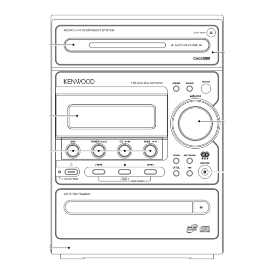
MICRO HI-FI COMPONENT SYSTEM
RXD-M55-H/M55-N/M55-S
RXD-M55E-H/M55E-N/M55E-S
SERVICE MANUAL
Front glass *
(B10-)
Front glass *
(B10-)
Knob *
(K29-)
Panel ass'y *
(A60-)
In compliance with Federal Regulations, following are repro-
duction of labels on, or inside the product relating to laser
product safety.
© 2002-4 PRINTED IN KOREA
B51-5790-00 (K/K) 3729
* Refer to parts list on page 25.
KENWOOD-Corp. certifies this equipment conforms to DHHS
Regulations No.21 CFR 1040. 10, Chapter 1, subchapter J.
DANGER : Laser radiation when open and interlock defeated.
AVOID DIRECT EXPOSURE TO BEAM.
Cassette lid *
(A53-)
Knob *
(K29-)
Miniature Phone jack
(E11-0399-05)
70%
Advertisement
Table of Contents

Related Manuals for Kenwood RXD-M55-H


Summary of Contents for Kenwood RXD-M55-H
- Page 1 * Refer to parts list on page 25. In compliance with Federal Regulations, following are repro- KENWOOD-Corp. certifies this equipment conforms to DHHS duction of labels on, or inside the product relating to laser Regulations No.21 CFR 1040. 10, Chapter 1, subchapter J.
-
Page 2: Table Of Contents
RXD-M55-H/M55-N/M55-S/M55E-H/M55E-N/M55E-S CONTENTS / ACCESSORIES / CAUTIONS Contents CONTENTS / ACCESSORIES ........2 WIRING DIAGRAM ...........18 EXTERNAL VIEW ............3 PC BOARD ...............19 DISASSEMBLY FOR REPAIR........4 SCHEMATIC DIAGRAM ...........24 BLOCK DIAGRAM ............5 EXPLODED VIEW ............33 CIRCUIT DESCRIPTION ..........6 PARTS LIST..............35 ADJUSTMENT ............16 SPECIFICATIONS ........Back cover... -
Page 3: External View
RXD-M55-H/M55-N/M55-S/M55E-H/M55E-N/M55E-S EXTERNAL VIEW Metallic cabinet * (A01-) Tuner ass'y * (W02-) 75 Ω ANTENNA AC power cord bushing (J42-) Lock terminal board * (E70-) FRONT SPEAKERS (6-16 Ω) AC power cord * (E30-) Pin jack (E63-1264-05) INPUT DIGITAL OPTICAL Oscillating module (W02-1114-15) * Refer to parts list on page 25. -
Page 4: Disassembly For Repair
RXD-M55-H/M55-N/M55-S/M55E-H/M55E-N/M55E-S DISASSEMBLY FOR REPAIR How to open the CD tray when it does not come out. 1. Insert a flat driver and so on to a square hole in the mechanism as shown in the figure. 2. Push a rack gear in the direction of arrow. - Page 5 X29,IC601 ATT. X29,J601 -8dB E.VOL LC75343M X29,Q111-114 SELECTOR AUX IN MAIN VOL.2 MAIN VOL.1 0 to -18dB 0 to -78dB POWER AMP INPUT VOL. TONE HEAD- W02-2919-05 (M TYPE) PHONE LOUDNESS BASS,MID,TRE W02-2920-05 (OTHERS) 10dB PLL DO SA CE A.OUT A.MUTE ON/STANDBY EX BASS...
-
Page 6: Circuit Description
RXD-M55-H/M55-N/M55-S/M55E-H/M55E-N/M55E-S CIRCUIT DESCRIPTION 1. Initializing 1-1 Initializing Method • While holding down the [POWER] key, plugged in the power cord to AC power wall outlet. 1-2 Initializing Operation • During the initial operation, the display shows "RESET" and after that it will be returned to standby condition. - Page 7 RXD-M55-H/M55-N/M55-S/M55E-H/M55E-N/M55E-S CIRCUIT DESCRIPTION 4. Test Mode 4-1 Setting method of the Test Mode Test Mode Keys Setting Method CD MODE CD PLAY key DECK MODE TAPE PLAY Insert the AC cord to AC wall ✽ SUB CLOCK OSC MODE key...
-
Page 8: Block Diagram
RXD-M55-H/M55-N/M55-S/M55E-H/M55E-N/M55E-S CIRCUIT DESCRIPTION 5. Microcomputer : MN101C51FGB(X29,IC701) 5-1 Microcomputer Periphery Block Diagram X28,IC1 DECK SYSTEM IC HA12230NT X14,IC501 FL DRIVER DECK MECHA. (MN12510F) X14,ED501 X29,IC601 Vaccume Fluorescent SYSTEM IC Display (LC75343M) X29,IC701 (HNA-14MS07T) MN101C51FGB X29,IC22 TUNER ASSY DSP IC PLL IC... - Page 9 RXD-M55-H/M55-N/M55-S/M55E-H/M55E-N/M55E-S CIRCUIT DESCRIPTION 5-2 Port Description of Microcomputer Active Pin No. Pin Name Pin Description VREF- Power supply (-) for A/D converter. Deck reel sensor input. TN TYPE Discrimination of tuner destination. S LEVEL RDS signal level input. (E/T version only) KEY1,KEY2 A/D key (1, 2) input.
- Page 10 RXD-M55-H/M55-N/M55-S/M55E-H/M55E-N/M55E-S CIRCUIT DESCRIPTION Active Pin No. Pin Name Pin Description SD detector input. Detected TU MUTE Tuner mute control. Mute ON PLAY SW Detection switch input of head position for deck. Playback REC R SW Deck reverse recording switch input.
- Page 11 RXD-M55-H/M55-N/M55-S/M55E-H/M55E-N/M55E-S CIRCUIT DESCRIPTION Pin No. Pin Name Pin Description KICK Kick pulse output for tracking driver. Tracking servo drive PWM output (-). Focus drive output. VREF Reference power supply for DA output pin. FBAL Focus balance adjusting output. TBAL Tracking balance adjusting output.
- Page 12 RXD-M55-H/M55-N/M55-S/M55E-H/M55E-N/M55E-S CIRCUIT DESCRIPTION 6-2 Channel BTL Driver : AN4801SB-E1(X29, IC23) Pin No. Pin Name Pin Description Driver 2 input. Power cut input (channel 2 mute). Driver 1 input. Power cut input (channel 1 mute). RESOUT Reset output. N.C. Unused. N.C.
- Page 13 RXD-M55-H/M55-N/M55-S/M55E-H/M55E-N/M55E-S CIRCUIT DESCRIPTION 6-4 Electronic Volume System IC : LC75343M : (X29, IC601) Pin No. Pin Name Pin Description Serial data input pin for control. Chip enable pin. Ground pin. LOPOUT Output pin of general-purpose operation amplifier. LINM Non-inverted input pin of general-purpose operation amplifier.
- Page 14 RXD-M55-H/M55-N/M55-S/M55E-H/M55E-N/M55E-S CIRCUIT DESCRIPTION 6-6 CD RF IC : AN8399SA-E1 (X29,IC21) Pin No. Pin Name Pin Description APC Amp input APC Amp output Power supply RF amp inverting input RF OUT RF addition amp output RF IN AGC amp input LDRCTL...
- Page 15 RXD-M55-H/M55-N/M55-S/M55E-H/M55E-N/M55E-S CIRCUIT DESCRIPTION Pin No. Pin Name Pin Description A120/70 Mode control input (connected to GND). Mode control input. B 1/11 Mode control input (connected to GND). PBOL PB left channel output. TAIL Tape left channel input. EQOL Equalizer left channel output (120u).
-
Page 16: Adjustment
RXD-M55-H/M55-N/M55-S/M55E-H/M55E-N/M55E-S ADJUSTMENT CD player adjustment INPUT OUTPUT PLAYER ALIGNMENT ITEM ALIGN FOR FIG. SETTING SETTING SETTING POINT Insert the AC cord to AC wall outlet while holding down the [CD PLAY/PAUSE] key. Connect the DC Press the "PLAY" key Test disc... -
Page 17: As Follow
RXD-M55-H/M55-N/M55-S/M55E-H/M55E-N/M55E-S ADJUSTMENT INPUT OUTPUT AMPLIFIER ALIGNMENT ITEM ALIGN FOR FIG. SETTINGS SETTINGS SETTINGS POINTS Unless otherwise specified, the individual switches should be set as following : POWER : ON Connect a DC voltmeter to VR1 (L) IDLE CURRENT – CN11 ( 1 2 ), Rch... -
Page 18: Wiring Diagram
(X14-7492-70) U.S.A. 490-11 SENSOR CN503 WH501 : RXD-M55E-S/-H/-N AUSTRALIA 490-71 (X14- ) (C/4) (X14-7XXX-XX) EUROPE 492-70 SHANGHAI 532-10 : RXD-M55-S/-H/-N RXD-M55-H (X14-749X-XX) RXD-M55-N (X14-749X-XX) DESTINATION DESTINATION UNIT No. UNIT No. COUNTRY ABB. COUNTRY ABB. CASSETTE U.S.A. 0-11 AUSTRALIA 0-71 MECHANISM... -
Page 19: Pc Board
PC BOARD(Component side view) X14-7492-70 A/4 (J70-1594-11) X14 D/4 X14 C/4 A501 VOLUME REPEAT SOUND CN501 CN503 R518 CD OPEN R534 R520 C502 W501 S513 S514 R517 C501 R516 W502 W503 R507 W515 C511 D503 R509 X14 B/4 R522 C504 R524 R523 C408... -
Page 20: Schematic Diagram
PC BOARD(Component side view) X29-2842-70 (J70-1577-21) C801 W120 R134 C808 W204 CN23 CN11 C803 R133 R804 W253 R902 C802 W123 R901 CN72 IC801 D105 IC901 D104 R727 R738 R722 R726 W159 W206 R718 R735 X801 R728 R724 R742 R723 R720 4.332MHz R761 Q702... - Page 21 PC BOARD (Component side view) X28-3202-70 A/2 (J70-1592-21) M.GND M+9V REC IN-LCH TA+9V BIAS-LCH BIAS-RCH Refer to the schematic diagram for the value of resistors and capacitors.
- Page 22 RXD-M55-H (X28-320X-XX) RXD-M55E-H (X28-3202-70) RXD-M55-S (X28-32XX-XX) DESTINATION DESTINATION DESTINATION UNIT No. UNIT No. UNIT No. COUNTRY ABB. COUNTRY ABB. COUNTRY ABB. U.S.A. EUROPE 2-70 U.S.A. 00-11 GENERAL MARKET 0-11 AUSTRALIA 00-11 RXD-M55E-N (X28-3202-70) KOREA EUROPE 02-70 YES YES EUROPE DESTINATION...
- Page 23 CD MECHANISM ASS'Y (X29-28XX-XX) (W02-2920-05) : E,T,H TYPE PICKUP ASS'Y CN21 TRK+ 9.3V 4.9V TRK- 3.3K R72 470K R71 2.2K R201 2.7K 3.3K R203 1 R38 1K VR1 (3.3K) 3.3u50 1u50 2.2K R204 1 (5.6) R205 1 6.9V R202 1 R211 2.2K DO/STEREO...
- Page 24 (X29-28XX-XX) POWER RELAY 4.8V DECK/TUNER : 18.1V CD RF IC21 (BOTTOM VIEW) CONT. CD : 17.7V Q111-114 2.6V 0.2V POWER C251 2.6V 3.8V -0.5V R255 2200P 2.6V 4.9V 9.3V 6.8K Q109 2.6V Q109 2.5V R223 R280 C260 C252 BIAS 2.5V 220u10 3.6K 1.8K...
- Page 25 220K ponents only with manufacturer's recommended parts (refer SHANGHAI 92-10 E70-0053-05 6.8K R33 390 to parts list). indicates safety critical components. For RXD-M55-H (X29-284X-XX) R123 1.1V continued protection against risk of fire, replace only with DESTINATION UNIT D10, 33.0V C720...
- Page 26 ABB. on the product. U.S.A. 490-11 F05-0070-05 L07-2758-05 AUSTRALIA 490-71 3300u16 EUROPE 492-70 F05-1222-05 L07-2858-05 SHANGHAI 532-10 100K 100K RXD-M55-H (X14-749X-XX) DESTINATION CN405, UNIT No. C402 C406 IC401 P401 R401 R402 R404 R514 R515 S401 T401 W404 COUNTRY ABB. U.S.A.
-
Page 27: Exploded View
RXD-M55-H/M55-N/M55-S/M55E-H/M55E-N/M55E-S EXPLODED VIEW(CD MECHANISM) ABx2 AAx2 AC x2 AC x2 : N09-2950-08 AB M6x5 : N09-2928-08 : N09-5280-05 Parts with exploded numbers larger than 700 are not supplied. - Page 28 AC220-240V~ AC110-120V~ X28 A/2 S401 X14 B/4 3x12 : N09-5412-05 : N82-2008-46 2.6x8 : N82-2608-46 : N86-4006-46 3x8(BLK) : N88-3008-45 : N89-3006-46 3x8(BLK) : N89-3008-45 : N89-3008-46 3x10(BLK) : N89-3010-45 3x10 : N89-3010-46 : N09-5431-05 3x12 : N09-0333-05 2.6x6(BLK) : N89-2606-45 REPEAT SOUND S513...
- Page 29 ✽ New Parts ✽ New Parts Parts without Parts No. are not supplied. Parts without Parts No. are not supplied. Les articles non mentionnes dans le Parts No. ne sont pas fournis. Les articles non mentionnes dans le Parts No. ne sont pas fournis. Teile ohne Parts No.
- Page 30 ✽ New Parts ✽ New Parts Parts without Parts No. are not supplied. Parts without Parts No. are not supplied. Les articles non mentionnes dans le Parts No. ne sont pas fournis. Les articles non mentionnes dans le Parts No. ne sont pas fournis. Teile ohne Parts No.
- Page 31 ✽ New Parts ✽ New Parts Parts without Parts No. are not supplied. Parts without Parts No. are not supplied. Les articles non mentionnes dans le Parts No. ne sont pas fournis. Les articles non mentionnes dans le Parts No. ne sont pas fournis. Teile ohne Parts No.
- Page 32 ✽ New Parts ✽ New Parts Parts without Parts No. are not supplied. Parts without Parts No. are not supplied. Les articles non mentionnes dans le Parts No. ne sont pas fournis. Les articles non mentionnes dans le Parts No. ne sont pas fournis. Teile ohne Parts No.
- Page 33 ✽ New Parts ✽ New Parts Parts without Parts No. are not supplied. Parts without Parts No. are not supplied. Les articles non mentionnes dans le Parts No. ne sont pas fournis. Les articles non mentionnes dans le Parts No. ne sont pas fournis. Teile ohne Parts No.
- Page 34 ✽ New Parts ✽ New Parts Parts without Parts No. are not supplied. Parts without Parts No. are not supplied. Les articles non mentionnes dans le Parts No. ne sont pas fournis. Les articles non mentionnes dans le Parts No. ne sont pas fournis. Teile ohne Parts No.
- Page 35 ✽ New Parts ✽ New Parts Parts without Parts No. are not supplied. Parts without Parts No. are not supplied. Les articles non mentionnes dans le Parts No. ne sont pas fournis. Les articles non mentionnes dans le Parts No. ne sont pas fournis. Teile ohne Parts No.
-
Page 36: Parts List
Korea Malaysia IC23 AN4801SB-E1 ANALOGUE IC RXD-M55E-H IC24 NJM4565M ANALOGUE IC RXD-M55E-N IC25 KIA7805API ANALOGUE IC RXD-M55E-S IC26 TA8409S MOS-IC RXD-M55-H IC101 KIA7805API ANALOGUE IC RXD-M55-N ✽ IC501 S-80840CNY ANALOGUE IC M1M2 RXD-M55-S IC601 LC75343M ANALOGUE IC MODEL ABB. Mexico... -
Page 37: Class
Tuning frequency range ..... 531 kHz ~ 1,602 kHz Weight (net) ..........5.3 kg (11.7 lb) KENWOOD follows a policy of continuous advancements in development. For t his reason specifications may be changed without notice. ÷ Sufficient performance may not be exhibited at extremely cold locations (where water freezes).