Table of Contents
Advertisement
SERVICE MANUAL
Ver 1.0 1999. 05
Frequency range
FM: 65.0 - 108 MHz
MW: 531 - 1,602 kHz
LW: 153 - 279 kHz
SW: 5.95 - 18 MHz
Aerials
FM/SW: Telescopic antenna
MW/LW: Built-in ferrite bar
Recording system
4-track, 2-channel stereo
Frequency response
70 - 10,000 Hz
Speakers
Full range: 10 cm (4 inches) dia.,
2.8 ohms cone type 2
Output
Headphones jack (stereo minijack),
for 16 - 68 ohms impedance headphones
Maximum power output
2.5 W + 2.5 W
MICROFILM
CFS-B5LMK2
Model Name Using Similar Mechanism
Tape Transport Mechanism Type
SPECIFICATIONS
Battery life
FM recording
Sony R20P: approx. 16 hours
Sony LR20 alkaline: approx. 36 hours
Playback
Sony R20P: approx. 8 hours
Sony LR20 alkaline: approx. 21 hours
Power requirements
230 V AC, 50 Hz
9 V DC, six R20 (size D) batteries
Power consumption
AC 14 W
Dimensions
Approx. 500
(19
6
3/4
1/8
and controls, not incl. handle
Mass
Approx. 2.7 kg (5 lb. 15 oz.) not incl. batteries
Supplied accessory
Mains lead (1)
Design and specifications are subject to change without
notice.
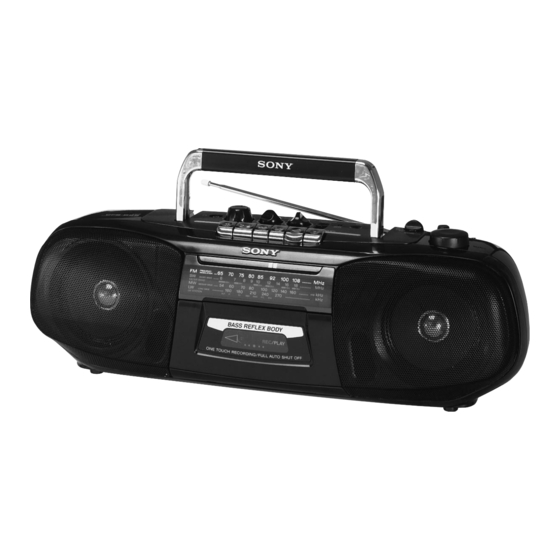
RADIO CASSETTE-CORDER
– 1 –
East European Model
155
164 mm (w/h/d)
6
inches) incl. projecting parts
1/2
NEW
MF-B5MK2-117
Advertisement
Table of Contents

Related Manuals for Sony CFS-B5LMK2


Summary of Contents for Sony CFS-B5LMK2
- Page 1 FM: 65.0 - 108 MHz FM recording MW: 531 - 1,602 kHz Sony R20P: approx. 16 hours LW: 153 - 279 kHz Sony LR20 alkaline: approx. 36 hours SW: 5.95 - 18 MHz Playback Aerials FM/SW: Telescopic antenna Sony R20P: approx. 8 hours MW/LW: Built-in ferrite bar Sony LR20 alkaline: approx.
-
Page 2: Table Of Contents
COMPONENTS IDENTIFIED BY MARK ! OR DOTTED LINE WITH MARK ! ON THE SCHEMATIC DIAGRAMS AND IN THE PARTS LIST ARE CRITICAL TO SAFE OPERATION. REPLACE THESE COMPONENTS WITH SONY PARTS WHOSE PART NUMBERS APPEAR AS SHOWN IN THIS MANUAL OR IN SUPPLEMENTS PUBLISHED BY SONY. - Page 3 SECTION 1 GENERAL This section is extracted from instruction manual. – 3 –...
- Page 4 – 4 –...
-
Page 5: Disassembly
SECTION 2 DISASSEMBLY The equipment can be removed using the following procedure. Set / Cabinet (front) sub assy (B) / Chassis (TUNE) / Tape mechanism block / Tuner, AC, Second board / Audio, Microphone, ISS board Note : Follow the disassembly procedure in the numerical order given. 2-1. -
Page 6: Tape Mechanism Block
2-3. TAPE MECHANISM BLOCK 3 CN601 4 tape mechanism block 2 CN301 1 BVTP 3x10 2-4. TUNER, AC, SECOND BOARD !¡ SECOND board 1 knob (FINE) 8 BVTP 3x10 6 CN911 0 AC board 9 BVTP 3x10 7 CN901 3 BVTP 3x10 4 CN1 2 BVTP 3x10 5 TUNER board... -
Page 7: Audio, Microphone, Iss Board
2-5. AUDIO, MICROPHONE, ISS BOARD !™ lSS board 1 knob (VOL) 2 knob (TONE) 3 chassis (MD) 6 MICROPHONE board !¡ tapping screw (3x12) 9 lever (FUNCTION) 5 SUPPORT board 4 BVTP 3x10 8 AUDIO board 7 BVTP 3x10 0 CN341 2-6. -
Page 8: Mechanical Adjustments
SECTION 3 SECTION 4 MECHANICAL ADJUSTMENTS ELECTRICAL ADJUSTMENTS PRECAUTION 4-1. TAPE RECORDER SECTION 0 dB = 0.775 V 1. Clean the following parts with a denatured alcohol-moistened swab : Standard Output Level record/playback head pinch roller Output terminal HP OUT erase head rubber belts load impedance... -
Page 9: Tuner Section
4-2. TUNER SECTION 0 dB = 1 µV FM FREQUENCY COVERAGE ADJUSTMENT • FM Section Adjust for a maximum reading on level meter. Setting: BAND switch: FM 64 MHz 109.5 MHz FM RF signal generator FM TRACKING ADJUSTMENT telescopic antenna input Adjust for a maximum reading on level meter. - Page 10 FM VCO Adjustment Setting: FM RF SSG 0.001 F telescopic antenna input Modulation: no modulation Output level: 0.1 V (100 dB) Procedure: 1. Adjust RV1 so that the reading on the frequency counter becomes in 76.0 kHz ± 50 Hz. Adjustment Location: tuner board –tuner board (conductor side)–...
-
Page 11: Diagrams
CFS-B5LMK2 SECTION 5 DIAGRAMS 5-1. BLOCK DIAGRAM POWER AMP PRE AMP R-CH IC305 IC301 J301 MIC301 PB IN S301-1 R-CH LINE R-CH (REC/PB) R-CH S302-2 S301-4 PB IN RV351-1 L-CH FUNCTION HRP101 LINE (REC/PB) (L-CH) TAPE REC/PB RADIO (RADIO OFF) -
Page 12: Circuit Boards Location
CFS-B5LMK2 5-2. CIRCUIT BOARDS LOCATION 5-3. PRINTED WIRING BOARD — TUNER SECTION — SECOND board ISS board MICROPHONE board SUPPORT board AC board BATTERY board TUNER board (Page 17) AUDIO board • IC Block Diagram IC1 CXA1538S • Semiconductor Note: •... -
Page 13: Schematic Diagram -Tuner Section
CFS-B5LMK2 5-4. SCHEMATIC DIAGRAM — TUNER SECTION — • Refer to page 13 for IC Block Diagram. (Page 20) Note: • All capacitors are in µF unless otherwise noted. pF: µµF • Voltage is dc with respect to ground under no-signal 50 WV or less are not indicated except for electrolytics (detuned) condition. - Page 14 CFS-B5LMK2 5-5. PRINTED WIRING BOARDS — MAIN SECTION — • Refer to page 13 for Circuit Boards Location. • Semiconductor Location Ref. No. Location D351 D352 D353 D901 D902 D903 F-10 D904 D911 IC301 IC305 Q151 Q251 Q340 Q341 (Page 14)
-
Page 15: Schematic Diagram -Main Section
CFS-B5LMK2 5-6. SCHEMATIC DIAGRAM — MAIN SECTION — (Page 16) • Waveform (MODE:REC) Note: • All capacitors are in µF unless otherwise noted. pF: µµF • U : B+ Line. • Voltages are taken with a VOM (Input impedance 10 M ). -
Page 16: Exploded Views
SECTION 6 EXPLODED VIEWS NOTE: • The mechanical parts with no reference • -XX and -X mean standardized parts, so • Accessories and packing materials and 6-2. CABINET (REAR) SECTION number in the exploded views are not supplied. they may have some difference from the hardware (# mark) list are given in •... -
Page 17: Tape Mechanism Deck Section (1)
6-3. TAPE MECHANISM DECK SECTION (1) (MF-B5MK2-117) HRP101 HE101 Ref. No. Part No. Description Remark Ref. No. Part No. Description Remark 3-933-010-01 SPRING (S/P), TORSION * 112 3-008-587-01 SLIDER (STOP) 3-933-025-01 SPRING (P), TORSION * 113 3-008-591-01 SLIDER (PAUSE) 3-933-026-01 LEVER (P) 3-933-004-01 CLAW, REEL 3-933-024-01 ROLLER, PINCH * 115... -
Page 18: Tape Mechanism Deck Section (2)
6-4. TAPE MECHANISM DECK SECTION (2) (MF-B5MK2-117) S902 M901 Ref. No. Part No. Description Remark Ref. No. Part No. Description Remark 3-933-029-01 LEVER, ERASING PREVENTION X-3373-572-1 REEL ASSY (N), T 3-933-182-01 SPRING, CASSETTE 3-933-020-01 BELT 3-932-995-01 GEAR (MID) X-3372-924-1 FLYWHEEL ASSY X-3371-667-1 CLUTCH ASSY 3-932-993-01 CHASSIS, OUTSERT 3-932-997-01 GEAR (CAM) -
Page 19: Electrical Parts List
SECTION 7 AUDIO ELECTRICAL PARTS LIST NOTE: • Due to standardization, replacements in • Items marked “*” are not stocked since The components identified by the parts list may be different from the they are seldom required for routine service. mark ! or dotted line with mark. - Page 20 AUDIO BATTERY MICROPHONE Ref. No. Part No. Description Remark Ref. No. Part No. Description Remark < JACK > R345 1-249-398-11 CARBON 1/4W R349 1-249-425-11 CARBON 4.7K 1/4W J301 1-566-891-11 JACK (2) R351 1-249-417-11 CARBON 1/4W R352 1-249-417-11 CARBON 1/4W < COIL > R353 1-249-437-11 CARBON 1/4W...
- Page 21 SECOND SUPPORT TUNER Ref. No. Part No. Description Remark Ref. No. Part No. Description Remark 1-670-173-21 SECOND BOARD 1-161-050-00 CERAMIC 0.0082uF 10% 1-162-282-31 CERAMIC 100PF ************** 1-162-282-31 CERAMIC 100PF < CAPACITOR > 1-162-195-31 CERAMIC 4.7PF 1-162-211-31 CERAMIC 33PF C901 1-101-005-00 CERAMIC 22000PF C902 1-101-005-00 CERAMIC...
- Page 22 CFS-B5LMK2 TUNER Ref. No. Part No. Description Remark Ref. No. Part No. Description Remark < COIL > MISCELLANEOUS *************** 1-416-838-11 COIL, AIR-CORE 1-416-851-11 COIL, AIR-CORE 1-769-412-11 CORD, POWER 1-754-001-21 ANTENNA, FERRITE-ROD (MW/LW) ANT1 1-501-918-21 ANTENNA, TELESCOPIC 1-406-252-11 COIL (OSC) HE101...
Need help?
Do you have a question about the CFS-B5LMK2 and is the answer not in the manual?
Questions and answers