Advertisement
Table of Contents
Service
Manual
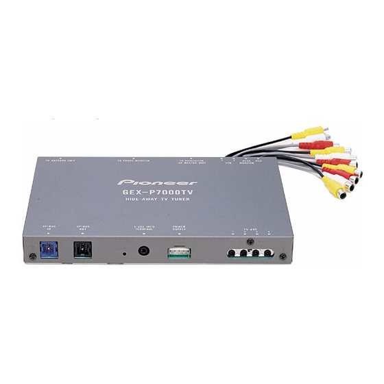
HIDE-AWAY TV TUNER
GEX-P7000TV
GEX-P7000TVP
- This product is a hide-away tuner, and cannot operate by itself. When operating this unit for servicing, switch to the
FM modulator mode with the slide switch located on the bottom plate.
- To receive the remote control data , connect the remote sensor , as shown below:
5V
Remote
sensor
CONTENTS
1. SAFETY INFORMATION ............................................2
2. EXPLODED VIEWS AND PARTS LIST .......................2
4. PCB CONNECTION DIAGRAM ................................23
5. ELECTRICAL PARTS LIST ........................................28
6. ADJUSTMENT..........................................................46
PIONEER ELECTRONIC CORPORATION
PIONEER ELECTRONICS SERVICE INC.
PIONEER ELECTRONIC [EUROPE] N.V.
PIONEER ELECTRONICS ASIACENTRE PTE.LTD. 253 Alexandra Road, #04-01, Singapore 159936
C PIONEER ELECTRONIC CORPORATION 1999
GEX-P7000TVP/EW
DSEN
REM
P.O.Box 1760, Long Beach, CA 90801-1760 U.S.A.
Haven 1087 Keetberglaan 1, 9120 Melsele, Belgium
GND
7. GENERAL INFORMATION .......................................49
7.1 IC ........................................................................49
7.2 CIRCUIT DESCRIPTION......................................58
8. OPERATIONS AND SPECIFICATIONS.....................60
4-1, Meguro 1-Chome, Meguro-ku, Tokyo 153-8654, Japan
ORDER NO.
CRT2385
EW,ES
K-ZZS. APR.1999 Printed in Japan
UC,ES
Advertisement
Table of Contents

Related Manuals for Pioneer GEX-P7000TV


Summary of Contents for Pioneer GEX-P7000TV
-
Page 1: Table Of Contents
PIONEER ELECTRONICS SERVICE INC. P.O.Box 1760, Long Beach, CA 90801-1760 U.S.A. PIONEER ELECTRONIC [EUROPE] N.V. Haven 1087 Keetberglaan 1, 9120 Melsele, Belgium PIONEER ELECTRONICS ASIACENTRE PTE.LTD. 253 Alexandra Road, #04-01, Singapore 159936 C PIONEER ELECTRONIC CORPORATION 1999 K-ZZS. APR.1999 Printed in Japan... -
Page 2: Safety Information
GEX-P7000TV,P7000TVP 1. SAFETY INFORMATION(GEX-P7000TV/UC) CAUTION This service manual is intended for qualified service technicians; it is not meant for the casual do-it-yourselfer. Qualified technicians have the necessary test equipment and tools, and have been trained to properly and safely repair complex products such as those covered by this manual. - Page 3 8 Screw HMF40P080FZK 9 Polyethylene Bag CEG1101 10 Remote Control Unit CXB4141 (2) CONTRAST TABLE GEX-P7000TV/UC, GEX-P7000TV/ES, GEX-P7000TVP/EW and GEX-P7000TVP/ES are constructed the same except for the following: Part No. Mark No. Symbol and Description GEX-P7000TV/UC GEX-P7000TV/ES GEX-P7000TVP/EW GEX-P7000TVP/ES 1-1 Card...
- Page 4 GEX-P7000TV,P7000TVP 2.2 EXTERIOR...
- Page 5 48 Spacer CNM6437 24 Cord See Contrast table(2) 25 Clamper CEF1008 (2) CONTRAST TABLE GEX-P7000TV/UC, GEX-P7000TV/ES, GEX-P7000TVP/EW and GEX-P7000TVP/ES are constructed the same except for the following: Part No. Mark No. Symbol and Description GEX-P7000TV/UC GEX-P7000TV/ES GEX-P7000TVP/EW GEX-P7000TVP/ES 5 Case...
-
Page 6: Block Diagram And Schematic Diagram
GEX-P7000TV,P7000TVP 3. BLOCK DIAGRAM AND SCHEMATIC DIAGRAM 3.1 BLOCK DIAGRAM(GEX-P7000TV) TV MODULATOR UNIT CN501... - Page 7 GEX-P7000TV,P7000TVP...
- Page 8 GEX-P7000TV,P7000TVP 3.2 BLOCK DIAGRAM(GEX-P7000TVP) TV MODULATOR UNIT CN501...
- Page 9 GEX-P7000TV,P7000TVP...
- Page 10 GEX-P7000TV,P7000TVP 3.3 OVERALL CONNECTION DIAGRAM(GUIDE PAGE)(GEX-P7000TV) Note: When ordering service parts, be sure to refer to “EXPLODED VIEWS AND PARTS LIST” or “ELECTRICAL PARTS LIST”. Large size SCH diagram Guide page Detailed page...
- Page 11 GEX-P7000TV,P7000TVP SWITCH: S1001:MODE SWITCH..FMMOD-MAIN UNIT-AV MASTER The underlined indicates the switch position.
- Page 12 GEX-P7000TV,P7000TVP...
- Page 13 GEX-P7000TV,P7000TVP...
- Page 14 GEX-P7000TV,P7000TVP...
- Page 15 GEX-P7000TV,P7000TVP...
- Page 16 GEX-P7000TV,P7000TVP 3.4 OVERALL CONNECTION DIAGRAM(GUIDE PAGE)(GEX-P7000TVP)
- Page 17 GEX-P7000TV,P7000TVP SWITCH: S1001:MODE SWITCH..FMMOD-MAIN UNIT-AV MASTER The underlined indicates the switch position.
- Page 18 GEX-P7000TV,P7000TVP...
- Page 19 GEX-P7000TV,P7000TVP...
- Page 20 GEX-P7000TV,P7000TVP...
- Page 21 GEX-P7000TV,P7000TVP...
- Page 22 GEX-P7000TV,P7000TVP 3.5 ANTENNA SELECT UNIT...
-
Page 23: Pcb Connection Diagram
GEX-P7000TV,P7000TVP 4. PCB CONNECTION DIAGRAM 4.1 ANTENNA SELECT UNIT NOTE FOR PCB DIAGRAMS 1. The parts mounted on this PCB include all necessary parts for several destination. For further information for respective destinations, be sure to check with the schematic dia- gram. - Page 24 GEX-P7000TV,P7000TVP 4.2 TV MODULATOR UNIT TV MODULATOR UNIT CORD DSEN NAVIGATION/ AV MASTER UNIT...
- Page 25 GEX-P7000TV,P7000TVP SIDE A V-SEL INFO IP-BUS OUT(BLACK) IP-BUS IN(BLUE) TERMINAL RESET MODE DSEN FRONT SENSOR and SPEAKER CN802:VTR1 CN501 MONITOR CN803:VTR2 CN804:REAR MONITOR...
- Page 26 GEX-P7000TV,P7000TVP TV MODULATOR UNIT...
- Page 27 GEX-P7000TV,P7000TVP SIDE B...
-
Page 28: Electrical Parts List
CKS.., CCS.., CSZS..=====Circuit Symbol and No.===Part Name Part No. =====Circuit Symbol and No.===Part Name Part No. ------ ------------------------------------------ ------------------------- ------ ------------------------------------------ ------------------------- Unit Number:CWM6345(GEX-P7000TV/UC) Transistor DTC124EU Transistor 2SA1037K Unit Number:CWM6510(GEX-P7000TV/ES) Transistor 2SC2412K Unit Name :TV Modulator Unit Transistor 2SC3295... - Page 29 GEX-P7000TV,P7000TVP =====Circuit Symbol and No.===Part Name Part No. =====Circuit Symbol and No.===Part Name Part No. ------ ------------------------------------------ ------------------------- ------ ------------------------------------------ ------------------------- 1008 Transistor 2SA1576 3810 Diode MA8062(M) 1801 Transistor 2SA1576 3811 Diode MA8062(M) 1802 Transistor 2SA1576 3812 Diode MA8062(M) 1803...
- Page 30 GEX-P7000TV,P7000TVP =====Circuit Symbol and No.===Part Name Part No. =====Circuit Symbol and No.===Part Name Part No. ------ ------------------------------------------ ------------------------- ------ ------------------------------------------ ------------------------- Inductor LCTB2R2K2125 2801 Inductor LCTA6R8J2520 Inductor LCTB2R2K2125 2802 Inductor CTF1379 Inductor LCTB2R2K2125 2805 Inductor LCTB101K2125 Inductor CTF1379 2806 Inductor...
- Page 31 GEX-P7000TV,P7000TVP =====Circuit Symbol and No.===Part Name Part No. =====Circuit Symbol and No.===Part Name Part No. ------ ------------------------------------------ ------------------------- ------ ------------------------------------------ ------------------------- RS1/16S154J RS1/8S470J RS1/16S223J RS1/16S103J RS1/16S682J RS1/16S102J RS1/16S393J RS1/16S102J RS1/16S103J RS1/16S102J RS1/16S103J RS1/16S102J RS1/16S622J RS1/16S102J RS1/10S822J RS1/16S102J RS1/16S473J RS1/16S681J RS1/16S682J...
- Page 32 GEX-P7000TV,P7000TVP =====Circuit Symbol and No.===Part Name Part No. =====Circuit Symbol and No.===Part Name Part No. ------ ------------------------------------------ ------------------------- ------ ------------------------------------------ ------------------------- RS1/10S620J RS1/10S472J RS1/10S473J RS1/10S472J RS1/10S473J RS1/4S271J RS1/10S102J RS1/4S271J RS1/10S102J RS1/10S472J RS1/10S103J RS1/10S472J RS1/10S473J RS1/10S103J RS1/10S473J RS1/10S103J RS1/10S103J RS1/10S102J RS1/10S103J...
- Page 33 GEX-P7000TV,P7000TVP =====Circuit Symbol and No.===Part Name Part No. =====Circuit Symbol and No.===Part Name Part No. ------ ------------------------------------------ ------------------------- ------ ------------------------------------------ ------------------------- 1806 RS1/16S331J 4016 RS1/16S104J 1807 RS1/16S102J 4017 RS1/16S104J 1808 RS1/16S331J 4018 RS1/16S104J 1809 RS1/16S102J 4019 RS1/16S104J 1811 RS1/10S0R0J 4020...
- Page 34 GEX-P7000TV,P7000TVP =====Circuit Symbol and No.===Part Name Part No. =====Circuit Symbol and No.===Part Name Part No. ------ ------------------------------------------ ------------------------- ------ ------------------------------------------ ------------------------- 4806 RS1/16S473J CKSRYB103K25 4808 RS1/16S0R0J CEV101M10 4811 RS1/16S471J 33µF/10V CCH1286 4812 RS1/16S471J CKSRYB473K16 4813 RS1/16S471J CEV470M6R3 4814 RS1/16S471J CKSRYB104K16...
- Page 35 GEX-P7000TV,P7000TVP =====Circuit Symbol and No.===Part Name Part No. =====Circuit Symbol and No.===Part Name Part No. ------ ------------------------------------------ ------------------------- ------ ------------------------------------------ ------------------------- CKSRYB104K16 1017 CCSRTH180J50 CKSRYB104K16 1018 CKSRYB102K50 CKSRYB104K16 1019 CKSRYB102K50 CKSRYB104K16 1020 CKSRYB102K50 CKSRYB104K16 1021 CKSRYB102K50 CKSRYB104K16 1022 CKSQYB224K16 CKSRYB104K16...
- Page 36 GEX-P7000TV,P7000TVP =====Circuit Symbol and No.===Part Name Part No. =====Circuit Symbol and No.===Part Name Part No. ------ ------------------------------------------ ------------------------- ------ ------------------------------------------ ------------------------- 1846 CCSRCH221J50 4041 CKSQYB105K16 1847 CCSRCH221J50 4042 CKSQYB105K16 1848 CCSRCH221J50 4043 CCSRCH151J50 2801 CKSQYB105K16 4044 CCSRCH151J50 2802 CCSRUJ121J50 4045...
- Page 37 GEX-P7000TV,P7000TVP =====Circuit Symbol and No.===Part Name Part No. =====Circuit Symbol and No.===Part Name Part No. ------ ------------------------------------------ ------------------------- ------ ------------------------------------------ ------------------------- IC 1806 NJM2267V Transistor 2SA1037K IC 1807 NJM2235M Transistor 2SD2396 IC 2801 PD5448B Transistor 2SD1760F5 IC 2804 TC74HC123AF Transistor...
- Page 38 GEX-P7000TV,P7000TVP =====Circuit Symbol and No.===Part Name Part No. =====Circuit Symbol and No.===Part Name Part No. ------ ------------------------------------------ ------------------------- ------ ------------------------------------------ ------------------------- Diode MA8051(M) Inductor CTF1379 1801 Diode MA152WK Inductor CTF1379 1802 Diode MA110 Inductor CTF1379 1803 Diode MA110 Inductor CTF1379...
- Page 39 GEX-P7000TV,P7000TVP =====Circuit Symbol and No.===Part Name Part No. =====Circuit Symbol and No.===Part Name Part No. ------ ------------------------------------------ ------------------------- ------ ------------------------------------------ ------------------------- 1006 Inductor LCTB2R2K3216 RESISTORS 1801 Inductor LCTB2R2K2125 1802 Inductor LCTB2R2K3216 RS1/16S104J 1803 Inductor LCTB2R2K3216 RS1/16S473J 1805 Inductor LCTB101K2125 RS1/16S113J...
- Page 40 GEX-P7000TV,P7000TVP =====Circuit Symbol and No.===Part Name Part No. =====Circuit Symbol and No.===Part Name Part No. ------ ------------------------------------------ ------------------------- ------ ------------------------------------------ ------------------------- RS1/16S472J RS1/16S473J RS1/16S102J RS1/16S103J RS1/16S102J RS1/16S562J RS1/16S102J RS1/16S332J RS1/16S223J RS1/10S182J RS1/16S362J RS1/10S472J RS1/16S681J RS1/10S223J RS1/16S242J RS1/10S224J RS1/16S822J RS1/10S224J RS1/16S103J...
- Page 41 GEX-P7000TV,P7000TVP =====Circuit Symbol and No.===Part Name Part No. =====Circuit Symbol and No.===Part Name Part No. ------ ------------------------------------------ ------------------------- ------ ------------------------------------------ ------------------------- RS1/16S750J 1018 RS1/16S103J RS1/16S102J 1019 RS1/16S391J RS1/16S102J 1020 RS1/16S105J RS1/16S471J 1022 RS1/16S223J RS1/16S471J 1023 RS1/16S393J RS1/16S471J 1024 RN1/16SE1202D RS1/16S750J...
- Page 42 GEX-P7000TV,P7000TVP =====Circuit Symbol and No.===Part Name Part No. =====Circuit Symbol and No.===Part Name Part No. ------ ------------------------------------------ ------------------------- ------ ------------------------------------------ ------------------------- 3835 RS1/16S471J 4206 RS1/10S102J 3836 RS1/16S223J 4301 RS1/10S104J 3838 RS1/16S0R0J 4302 RS1/10S104J 4001 RS1/16S272J 4303 RS1/10S104J 4002 RS1/16S272J 4304...
- Page 43 GEX-P7000TV,P7000TVP =====Circuit Symbol and No.===Part Name Part No. =====Circuit Symbol and No.===Part Name Part No. ------ ------------------------------------------ ------------------------- ------ ------------------------------------------ ------------------------- CKSRYB103K25 CKSRYB103K25 CCSRCH101J50 CKSYB106K6R3 CKSQYB474K16 CKSRYB103K25 CCSRCH160J50 CKSYB106K6R3 CKSYB106K6R3 470µF/6.3V CCH1182 CEV220M10 470µF/6.3V CCH1182 CKSQYB474K16 CKSYB106K6R3 CKSYB106K6R3 CKSRYB223K25 CKSRYB104K16...
- Page 44 GEX-P7000TV,P7000TVP =====Circuit Symbol and No.===Part Name Part No. =====Circuit Symbol and No.===Part Name Part No. ------ ------------------------------------------ ------------------------- ------ ------------------------------------------ ------------------------- 1002 CEAS220M50 1842 CKSYB106K6R3 1003 CKSQYB473K16 1843 CKSQYB103K25 1004 470µF/10V CCH1019 1844 CKSQYB103K25 1005 470µF/10V CCH1019 1845 CKSYB106K6R3 1006...
- Page 45 GEX-P7000TV,P7000TVP =====Circuit Symbol and No.===Part Name Part No. ------ ------------------------------------------ ------------------------- 4047 CKSQYB105K16 4048 CKSQYB105K16 4049 CKSRYB222K50 4050 CKSRYB222K50 4051 CEJA101M10 4052 CEJA100M16 4053 CEJA101M10 4055 CCSRCH151J50 4056 CCSRCH151J50 4057 CCSRCH151J50 4058 CCSRCH151J50 4201 CEJA1R0M50 4202 CEJA1R0M50 4203 CEJA1R0M50 4204...
-
Page 46: Adjustment
GEX-P7000TV,P7000TVP 6. ADJUSTMENT - Test Point Center Oscilloscope DC V Meter Meter TV MODULATOR UNIT MODE DC V Meter Oscilloscope Linear ANTENNA DC V Meter SELECT UNIT Detector - Adjustment Point TV MODULATOR UNIT... - Page 47 GEX-P7000TV,P7000TVP Before adjustment, set the diversity to 1 so as to prevent the circuit from operating during input signals are weak (use “1” input for antenna input). Use rear monitor or OSD output for the video monitor. Procedure Adjustment Input signal...
- Page 48 GEX-P7000TV,P7000TVP Procedure Adjustment Input signal Adjustment Adjustment method Item Point Play a VR501 Set the MODE switch (S1001) to the FM modulator mode. Connect a modulator multi-CD and start-up the source with the CD. Set the modulator 38 kHz frequency to 89.1 MHz on the menu screen. Monitor pin 14 of IC501...
-
Page 49: General Information
GEX-P7000TV,P7000TVP 7. GENERAL INFORMATION 7.1 IC - Pin Functions (PE5039A) Pin No. Pin Name Format Function and Operation Not used AVSS A/D GND SNCOUT Stereo noise control output(Not used) HCCOUT High cut level output(Not used) AVREF1 A/D converter reference voltage... - Page 50 GEX-P7000TV,P7000TVP Pin No. Pin Name Format Function and Operation Crystal oscillator connection pin Connect to GND Not used TESTIN Test program mode input AVDD Connect to VDD AVREFO Connect to VDD Signal level input MODEL1 Mode switch select input SIMUKE...
- Page 51 GEX-P7000TV,P7000TVP - Pin Functions (PE5040A) Pin No. Pin Name Format Function and Operation TVPWIN TV power on request input TVMTIN TV mute on request input ASENBO ASENBO output AVSS A/D GND TPDO FM transmitter PLL data output TPCK FM transmitter PLL clock output...
- Page 52 GEX-P7000TV,P7000TVP Pin No. Pin Name Format Function and Operation Crystal oscillator connection pin Connect to VSS Not used TESTIN Test program mode input AVDD Positive power supply terminal for analog circuit AVREFO Connect to VDD MODEL1 Mode switch select input...
- Page 53 GEX-P7000TV,P7000TVP BU2611AFS PHASE DET. CHARGE PUMP 4BIT 1/16 MAIN COUNT COUNT 1/17 REFERENCE DIVIDER SHIFT REGISTER LATCH PM0013AM LPFOUT LPFIN AST VMODE AVDD DVDD RESB ANT1 ANT2 ANT3 ANT4 ANTENNA SYNC. INPUT RESET SWITCHING SEPA. OUTPUT DRIVER DIGITAL SYNC. SIGNAL SEPA.
- Page 54 GEX-P7000TV,P7000TVP - Pin Functions (PD5448B) Pin No. Pin Name Function and Operation OSC1 Oscillator for display OSC2 Oscillator for display Chip select input Serial clock input Serial data input Auto clear input 7-10 P6-P9 Not used BLNK Port output R output...
- Page 55 GEX-P7000TV,P7000TVP CXA2060BS APED XTAL 1 C1 IN XTAL 2 ABL IN XTAL 3 CVBS1/Y1 IN APC FIL V TIM VCC2 MON OUT TV/C2 IN COMB C IN ABL FIL Y CLAMP CVBS2/Y2 IN COMB Y IN GND2 GND1 EB-Y IN...
- Page 56 GEX-P7000TV,P7000TVP CXA2061S APED 48 NC C1 IN X'tal ABL IN FSCOUT CVBS1/Y1 IN APC FIL V TIM VCC2 MON OUT TV/C2 IN COMB-C IN ABL FIL Y CLAMP CVBS2/Y2 IN COMB-Y IN GND2 GND1 EB-Y IN ER-Y IN I REF...
- Page 57 GEX-P7000TV,P7000TVP - TV Front End (FE1001:CWB1085) - TV Front End (FE1001:CWB1086)
-
Page 58: Circuit Description
GEX-P7000TV,P7000TVP 7.2 CIRCUIT DESCRIPTION - Multi-SIF GEX-P7000TVP/EW and /ES adopt the multi-Sound IF method in order to support overseas TV broadcasting methods. /EW and /ES are compatible with broadcasting methods B, G, H, D, K and I. The frequency difference between the video and sound carriers is 5.5 MHz for broadcasting methods B, G and H, 6 MHz for I or 6.5 MHz for D and K. - Page 59 GEX-P7000TV,P7000TVP Since detection circuits cannot be unified into one even with the above conversion, turn the IF to 6.0 MHz for all meth- ods by utilizing a frequency difference of 0.5 MHz between each IF. When IF = 5.5 or 6.5 MHz: Mix an oscillator of 0.5 MHz to turn it to 6.0 MHz.
-
Page 60: Operations And Specifications
MODE. (1) AV MASTER MODE (IP-BUS AV MASTER) When combining with a PIONEER Audio Visual Master Unit (e.g. AVM-P7000R): • Audio is output from the Audio Visual Master Unit’s TV source. • Perform operations with this product and the Audio Visual Master Unit. - Page 61 GEX-P7000TV,P7000TVP 2. Gray 3. Green 1. Navigation System (sold separately) 4. Audio Visual Master Unit 3. Green 5. Connect a display that does (sold separately) not feature an IP-BUS cable in the same way as in *1. 7. Blue 6. RGB cable (supplied with the Audio 8.
-
Page 62: Specifications
GEX-P7000TV,P7000TVP 8.2 SPECIFICATIONS - GEX-P7000TVP/EW General Power source ....................14.4 V DC (10.8 — 15.1 V allowable) Grounding system ..........................Negative type Max. current consumption ..........................2 A Dimensions ......................237 (W) 28 (H) 171 (D) mm Weight ................................1.1 kg TV tuner Reception channel/TV system ....
Need help?
Do you have a question about the GEX-P7000TV and is the answer not in the manual?
Questions and answers