Philips LX3700D Service Manual
Philips dvd receiver service manual
Hide thumbs
Also See for LX3700D:
- User manual (35 pages) ,
- Owner's manual (33 pages) ,
- Specifications (2 pages)
Table of Contents
Advertisement
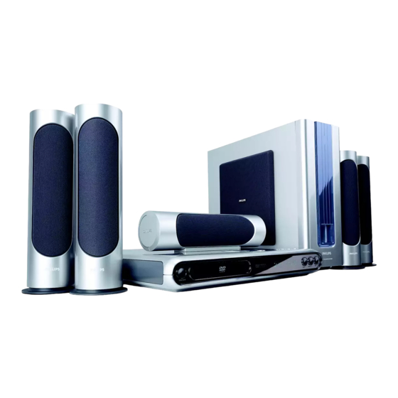
DVD Receiver
Service
Service
Service
Service
Service
Service Manual
©
Copyright 2002 Philips Consumer Electronics B.V. Eindhoven, The Netherlands
All rights reserved. No part of this publication may be reproduced, stored in a retrieval system or
transmitted, in any form or by any means, electronic, mechanical, photocopying, or otherwise
without the prior permission of Philips.
Published by SL-ET0319 Service Audio Printed in The Netherlands Subject to modification
Version 1.1
LX3700D
TABLE OF CONTENTS
Location of PC Boards ................................................ 1-2
Versions Variation & Package .................................... 1-2
Specifications .............................................................. 1-3
Measurement Setup ................................................... 1-4
Service Aids ................................................................ 1-5
ESD & Safety Instruction ............................................ 1-6
Functional Overview ......................................... 1-7 to1-8
Connections & Troubleshooting .............................. 1-13
Wireless System Information ................................... 1-14
Setting Procedure & Repair Instructions ....................... 2
Block & Wiring Diagram ................................................ 4
Control & Speaker Jack Board ...................................... 5
RGB & Scart Board ....................................................... 6
DVD Module .................................................................. 7
Main Board (Include Headphone Board) ...................... 8
Power Board .................................................................. 9
Mechanical Exploded View & Parts List ...................... 10
Wireless Surround Loudspeaker Boxes ...................... 11
LX3700D
/21S/21R/22S/25S
LX3750W
LX3750W
COMPACT
Page
DIGITAL AUDIO
CLASS 1
LASER PRODUCT
GB
/22S/25S/37
3140 785 32590
Advertisement
Chapters
Table of Contents

Related Manuals for Philips LX3700D


Summary of Contents for Philips LX3700D
-
Page 1: Table Of Contents
LASER PRODUCT © Copyright 2002 Philips Consumer Electronics B.V. Eindhoven, The Netherlands All rights reserved. No part of this publication may be reproduced, stored in a retrieval system or transmitted, in any form or by any means, electronic, mechanical, photocopying, or otherwise without the prior permission of Philips. -
Page 2: Location Of Pc Boards
LOCATION OF PC BOARDS VERSION VARIATION: LX3700D Type/Versions LX3700D LX3700D LX3700D LX3750W LX3750W LX3750W Features & /21R /21S /22S /25S /22S /25S Board in used RDS function Progressive scan Scart board RGB board Power PCB(120V) Power PCB(110V~127V/220V~240V) Power PCB(220V~240V) AC Voltage Selector... -
Page 3: Specifications
SPECIFICATIONS MISCELLANEOUS / GENERAL SECTION AMPLIFIER SECTION Power Supply Rating....110-127V/220-240V, 50/60Hz Power Output /21R/21S - Stereo mode (DIN)..........2 x 50 W ....220-240V/50Hz /22S/25S - Surround mode (1 kHz)......50 W RMS/channel ......110-127V/60Hz /37 Total Harmonic Distortion...10 % at rated power (1 kHz) Power Consumption.......... -
Page 4: Measurement Setup
MEASUREMENT SETUP AC MILLIVOL TME TER AUTO DISTORTION METER LOAD 4 OHM AC MILLIVOL TME TER AUTO DISTORTION METER LOAD 4 OHM OSCIL LOSCOPE OSCIL LOSCOPE ..........INPUT INPUT LOOP AM LOOP ANT SIGNAL GENERATORAC SIGNAL GENERATORAC AM-FM STEREO SIGNAL AM-FM STEREO SIGNAL GENERATOR... -
Page 5: Service Aids
SERVICE AIDS ESD Equipment: Service Tools: Anti-static table mat - large 1200x650x1.25mm ...4822 466 10953 Universal Torx driver holder .........4822 395 91019 anti-static table mat - small 600x650x1.25mm ..4822 466 10958 Torx bit T10 150mm ...........4822 395 50456 Anti-static wristband ..........4822 395 10223 Torx driver set T6-T20 .........4822 395 50145 Ω) Connectorbox (1M... - Page 6 WAARSCHUWING WARNING Alle IC’s en vele andere halfgeleiders zijn All ICs and many other semi-conductors are gevoelig voor electrostatische ontladingen susceptible to electrostatic discharges (ESD). (ESD). Careless handling during repair can reduce life Onzorgvuldig behandelen tijdens reparatie kan drastically. de levensduur drastisch doen verminderen. When repairing, make sure that you are Zorg ervoor dat u tijdens reparatie via een connected with the same potential as the mass...
-
Page 7: Functional Overview
FUNCTIONAL OVERVIEW... - Page 8 FUNCTIONAL OVERVIEW...
-
Page 9: Preparations & Connections
PREPARATIONS AND CONNECTIONS... - Page 10 1-10 PREPARATIONS AND CONNECTIONS...
- Page 11 1-11 PREPARATIONS AND CONNECTIONS...
- Page 12 1-12 PREPARATIONS AND CONNECTIONS...
-
Page 13: Connections & Troubleshooting
1-13 CONNECTIONS AND TROUBLESHOOTING... -
Page 14: Wireless System Information
1-14 AD905W WIRELESS SYSTEM INFORMATION... - Page 15 Select the menu using the " " and " " button on R/C After replacement / repair of the MPEG board, the customer c) TV Show "TUNER AREA ADJUST" For LX3700D/22S (Europe) c) Go feature setup page select "PASSWORD". TV show setting and the region code may lost. Changing the Region <PLAY>...
- Page 16 REPAIR INSTRUCTION IC501 Only CN502 IC401 CN213 CN906 RB906 TO CN906 and IC502 CN213 CN905 Only C/ RS CN502 IC401 IC201 Standby IC503 IC401 Only LS/SW CN503 IC401 IC9001 IC9002 Check IC401 pin 7, 8, 9 Check IC401 IC1003 I S Signal Circuit Check pin 10, 11, 20 CLK...
- Page 17 REPAIR INSTRUCTION Q9034 Q9032 Q9032 Q9034 IC101, IC152 IC1003 (LC72131-CE , DI/DO,CLK) IC1003 TO IC152 IC3001 IC1009 TO IC305, IC306 RB3001 IC4001 Q3001 IC307 Circuit CN3001 Q3002 CN3001 pin is OK ? IC305, IC306, IC4001 IC4001 IC1009 TO IC301-A JK301, JK302-A TO IC1003 IC307 TO IC304 and IC302 Q303, Q304...
-
Page 18: Disassembly Instructions
DISASSEMBLY INSTRUCTIONS Dismantling of the Key Board 1) Loosen 2 screws "C" at the top of the button as shown in Dismantling of the Front Panel Assembly figure 6. 1) Open the DVD Tray by using the Open/Close Button 2) Return the set to its upright position and remove the Tray 2) Loosen 6 screws"D"... - Page 19 SERVICE POSITIONS Service position A Scart Jack use for LX3700/22S ,/25S RGB Jack use for LX3700/21S ,LX3750/37S Figure 11 Figure 12 Dismantling of the Power Board 1) Loosen 6 screws "H" at the top of the Power Board as shown in Service position B figure 13 Figure 13...
-
Page 20: Block & Wiring Diagram
BLOCK DIAGRAM... - Page 21 WIRING DIAGRAM...
-
Page 22: Control & Speaker Jack Board
CF745 INTERNAL BLOCK DIAGRAM 9-1 1 T0CKI OSC1 OS C 2 MCLR CONFIGURATION WORD EPROM /ROM 9- 11 STAC K 1 512 X 12 TO STAC K 2 “OSC “DISAB LE ” 2048 X 12 SELECT ” WA TCHDOG “CODE TI MER OSCILLATO R/ PROTECT ”... -
Page 23: Circuit Diagram
CIRCUIT DIAGRAM C201 R243 C202 R244 C203 R248 C204 RB211-B C1 C205 RB213 C206 RB214 C207 RB216 C208 RB217 C209 R218A C210 R218B C211 RB212-B C3 C212 RB3001 C214 SN201 C215 TA201 C216 TA202 C217 TA203 C218 TA204 CN211-B C1 TA205 CN202-B C3 TA206... - Page 24 PCB LAYOUT TOP VIEW C119 Q204 C120 R201 C121 R202 C122 R203 C201 R204 C202 R205 C203 R206 C204 R207 C205 R208 C206 R209 C207 R210 C208 R211 C209 R212 C210 R213 C211 R214 C212 R215 C214 R216 C215 R217 C216 R218 C217...
- Page 25 ELECTRICAL PARTSLIST - CONTROL BOARD - MISCELLANEOUS - CN211B 9965 000 18027 CONNECTOR 8P CN212B 9965 000 18028 CONNECTOR 5P CN213 9965 000 18029 CONNECTOR 3P CN217 9965 000 18030 CONNECTOR 2P DP201 9965 000 18031 VFD 100X25MM JK3001 9965 000 18032 D3.5 9P NICKEL LD201 9965 000 17400...
-
Page 27: Rgb & Scart Board
RGB & SCART BOARD TABLE OF CONTENTS RGB Circuit Diagram (For /21S/21R/37 only).... 6-2 RGB Board Layout (For /21S/21R/37 only) ....6-2 Scart Circuit Diagram (For /22S/25S only) ....6-3 Scart Board Layout (For /22S/25S only) ....6-3 Electrical Parts List(RGB &... - Page 28 CIRCUIT DIAGRAM - RGB BOARD C181 C185 FB181 JK182 RB181 ZD183 ZD186 C186 C182 FB182 JK183 ZD181 ZD184 C183 C187 FB183 JK184 ZD182 ZD185 PCB LAYOUT - RGB BOARD C181 C185 FB181 JK182 RB181 ZD183 ZD186 C186 C182 FB182 JK183 ZD181 ZD184 C187...
- Page 29 CIRCUIT DIAGRAM - SCART BOARD C1001 C1002 C1003 C1004 C1005 C1006 C1007 C1008 C1009 CN101A A4 CN101B A4 FB137 FB138 FB139 FB140 FB141 FB142 FB144 FB145 FB146 FB147 JK103 JK401 JK2001 R1001 R1002 R1003 RB1002 A4 ZD1101 A3 ZD1103 A3 ZD1104 A3 ZD1105 B3 ZD1106 B2...
- Page 30 ELECTRICAL PARTSLIST - RGB BOARD ELECTRICAL PARTSLIST - SCART BOARD - MISCELLANEOUS - - MISCELLANEOUS - JK182 9965 000 18044 JACK 1P W/GND CN101A 9965 000 18015 CONNECTOR 3P JK183 9965 000 12607 DIN JACK, S-VIDEO OUT CN101B 9965 000 15900 CONNECTOR 3P JK184 9965 000 12609...
-
Page 31: Dvd Loader
DVD LOADER It is not recommended for component repair on this Module but to replace the major assembly when it becomes defective. Therefore limited service parts list are published in this chapter. Explorer View - DVD Loader... -
Page 32: Mechanical Parts List
MECHANICAL PARTS LIST M1010000013 MAIN BASE 62300000100 PULLEY LOADING 62300000200 GEAR LOADING 62300000300 GEAR PULLEY 62230000102 LEVER SWITCH 62230000202 CAM SLIDE 62230000304 LEVER LIFT PU 61050000900 BASE P/U OUT 62300001800 SLIDE STEP 62230001800 SUPORT PU 62350000301 CAP G/S SKY 62230000901 TRAY 62230001700 CLAMP... - Page 42 8-10 8-10 CIRCUIT DIAGRAM (TOP LEFT) C001 C3035 R119 C003 C9002 R122 C005 C9003 R123 C006 C9004 R124 C007 C9005 R125 C008 C9006 R126 C009 C9007 R129 C010 C9008 R130 C011 C9009 R131 C012 C9010 R132 C014 C9011 R133 C015 C9013 R134 C016...
- Page 43 8-11 8-11 CIRCUIT DIAGRAM (TOP RIGHT) C213 R1028 C1012 R1029 C1013 R1030 C1014 R1031 C1015 R1032 C1016 R1033 C1017 R1034 C1023 R1036 C1024 R1037 C1036 R1038 C1037 R1039 BEAD 100 OHM AT 100 MHZ C1038 R1040 C1039 R1061 C1040 R1062 C1041 R1071 C1042...
- Page 44 8-12 8-12 CIRCUIT DIAGRAM (BOTTOM LEFT) C301 D9002 R381 C302 IC301 R382 C303 IC302 R383 R384 C304 IC301-A-A F4 R385 C305 IC301-A-B F4 R386 C306 IC304-A R387 C307 IC304-B IC305-A R390 C308 IC305-B R391 C309 C311 IC306-A R392 C312 IC306-B R393 C313 IC307-A...
- Page 45 8-13 8-13 CIRCUIT DIAGRAM (BOTTOM RIGHT) C401 C1132 C402 C1133 C403 C2208 C404 C4001 C405 C4002 C406 C4003 C407 C4004 C408 C4005 C409 C4006 C410 C4007 C411 C4008 C412 C5011 C413 C5012 C414 C5031 C415 C5032 C416 C5033 C417 C5034 C418 C5035 C419...
- Page 46 8-14 8-14 PCB LAYOUT (COMPONENT VIEW)
- Page 47 8-15 LAYOUT MAPPING (COMPONENT VIEW) C001 A1 C369 A6 C1031 B6 D9002 C4 R007 B1 R395 R3025 C005 A1 C370 B4 C1032 B6 EF001 A2 R103 A2 R396 R3026 C011 A3 C371 A5 C1033 B6 FB1001 C5 R104 A2 R397 R3027 C012 A3 C372 A4...
- Page 48 8-16 LAYOUT MAPPING (COPPERSIDE VIEW) C003 C1077 R1089 C006 C1078 R1091 C007 C1079 R1092 C008 C1080 R1090 C009 C1083 R2002 C010 C1084 R3004 C013 C1086 R3005 C015 C1100 R3021 C016 C1102 R3022 C108 C1104 R3032 C111 C1106 R3033 C112 C1107 R3034 C1110 R3035...
- Page 49 8-17 8-17 PCB LAYOUT (COPPERSIDE VIEW)
- Page 50 8-18 8-18 ELECTRICAL PARTSLIST - MAIN BOARD ELECTRICAL PARTSLIST - MAIN BOARD - MISCELLANEOUS - - RESISTORS - - COILS & FILTERS -- DIODES - CN002 9965 000 15855 CONNECTOR S2B-XH-A 2P RA1006 9965 000 12486 RES ARRAY 4*33 Ω 1/10W 5% L1003 9965 000 15871 INDUCTOR 10 µH 10% ZD302...
- Page 51 8-19 ELECTRICAL PARTSLIST - MAIN BOARD - IC & TRANSISTORS - IC1012 9965 000 17379 IC SN74HCT244DW IC1013 9965 000 17380 IC AK4112BVF IC1015 9965 000 17381 IC WM8738ED IC3001 9965 000 12510 TC4052BFN CHIP IC3002 9965 000 15886 IC RC4558D IC4001 9965 000 15886 IC RC4558D IC9001...
- Page 52 8-20...
-
Page 53: Power Board
TL431 EQUIVALENT SCHEMATIC CATHODE 20 pF 3.28 k 10 k POWER BOARD 20 pF 2.4 k 7.2 k ANODE TABLE OF CONTENTS Internal IC Diagram & Voltage.........9-1 Circuit Diagram.............. 9-2 TOP249 BLOCK DIAGRAM PCB Layout ..............9-3 Electrical Parts List............9-4 CONTROL (C) DRAIN (D) INTERNAL... - Page 54 CIRCUIT DIAGRAM BR901 C908 C919 C933 C949 C966 CN902 D908 L903 R903 R921 R932 R949 RL901 ZD903 A6 C901 C909 C920 C938 C950 C967 D901 D909 Q903 R904 R922 R941 R950 RT901 A3 ZD904 B5 C902 C910 C925 C939 C951 C968 D902 D910...
- Page 55 POWER PCB LAYOUT BR901 B2 JMP1 C901 JMP2 C902 JMP3 C903 JMP4 C904 JMP5 C905 JMP6 C906 K901 C907 L901 C908 L902 C909 L903 C910 C911A C2 P901 C911B C3 P902 C912 Q903 C913 Q904 C914 Q910 C919 Q912 C920 Q913 C925 R901...
- Page 56 ELECTRICAL PARTSLIST - POWER BOARD - MISCELLANEOUS - - DIODES - CN902 9965 000 15936 CONNECTOR 4P P=3.96MM D905 9965 000 14186 MUR1620CT 8A 200V CN903 9965 000 17458 CONNECTOR 3P /21S/21R D906 5322 130 32677 1N5822 CN904 9965 000 16340 CONNECTOR 5P /21S/21R D907 9965 000 14187...
- Page 57 10-1 10-1 EXPLODED DRAWING LX3700 \21S ONLY LX3700 \22S ONLY LX3700 \25S ONLY LX3700 \37S ONLY...
- Page 58 9965 000 19313 SIDE PANEL(R) / LX3750W/22S/25S 9965 000 18013 BACK PANEL /22S/25S 9965 000 18372 BACK PANEL / LX3750W/37 9965 000 18373 BACK PANEL / LX3700D/21R 9965 000 18374 BACK PANEL / LX3700D/21S 9965 000 12443 AC SLOT /21S/21R/22S/25S...
- Page 59 10-3...
- Page 60 WIRELESS SURROUND LOUDSPEAKER BOXES TABLE OF CONTENTS Introduction ............11-1 Mechanical instructions - Mech. Partslist ..... 11-1 Service hints ............11-2 Blockdiagrams ............11-4 Wiring ..............11-6 Electrical Diagrams ..........11-7 Circuit Descriptions ..........11-21 Spare Partslist ............11-26...
-
Page 61: Introduction
11-1 11-1 11. Wireless Surround Loudspeaker boxes 1.1. Introduction 1.2. Mechanical Intructions With the Wireless surround system it is possible to connect 1.2.1. EV drawings + mechanical partslists rear speakers wireless with the main set. The system consists of:transmitter part Tx: interface-board and transmitter board receiver part RX: receiver board, amplifier board and SMPSupply part Loudspeaker boxes left and right rear, per equipment defined. -
Page 62: Service Hints
11-2 11-2 1.3. Service hints, faultfinding and alignments 1.3.1 Measurement setup wireless receiver test circuit wireless transmitter test circuit WirelessReceiver functional check and adjustment table Audio AD905W (LX3750W) versions To RX input F150 L + R e.g. PM2534 F114 AC-mV meter Powersupply Measurement 68 E... - Page 63 11-3 11-3 1.4 Block Diagram TX TRANSMITTER INTERFACE Power Supply 6140 7100 7105 L4931CDT120 HT7550 7145 F015 1100 F021 14VDC 1130 F001 7140 PIC12C508A SUPPLY F016 UNIT "ON" F002 Channel Selection DRIVER F017 Switch +12V 4 positions F018 F020 7130,7101,6130 TRIG 1125 WIRED...
- Page 64 11-4 11-4 1.5 Block Diagram RX RECEIVER / FRONT END RECEIVER / BACKEND - EXPANDER - 7780 7770 7601 7602 7710 7707 SA572D NJM4565M LA1836M 1602 BFC520 BFR92A 5606 1706 BF520 1707 2703, 3727 1790 F712 F728 DE-EMPH. (LOW STEREO ∆G MIXER AMPLIFIER...
-
Page 65: Wiring
11-5 11-5 1.6 Wiring Diagram Wiring Diagram Wireless Transmitter/Receiver AD905W AC/DC Interface board Transmitter board Supply unit 8002 TX 8003 TX 1120 1101 From 8001 TX LX3750W 1125 LS output Wired Audio in (option) 8002 RX Amplifier board AC/DC Receiver board Switch Mode 8004 RX 1104... -
Page 66: Electrical Diagrams
11-6 11-6 1.7 Electrical Diagrams 1.7.1 Wireless Interface Board 1100 A 1 3148 D 6 1110 D 1 3151 F10 1120 E21 3152 G 6 1125 J1 3154 D 13 +12V 1130 I 19 3155 F13 7100 7105 DC jack TR A N SM I TTER I N TER FA C E 2100 B 2 4115 C 18... - Page 67 11-7 11-7 Layout Wireless Interface Board (Top Side) Layout Wireless Interface Board (Bottom Side) CL36532008_094.eps 220403 CL36532008_095.eps 220403...
- Page 68 11-8 11-8 1.7.2 Wireless Transmitter Board 0001 D1 3115 D 7 F119 E2 0002 B 15 3116 A 8 F120 F2 1101 E2 3117 A 10 F121 F3 1102 A 14 3118 B 10 F122 F4 1105 C 2 3119 C 8 F123 E5 TR A NS M I TTER 1106 I 12...
- Page 69 11-9 11-9 Layout Wireless Transmitter Board (Top Side) CL36532008_097.eps 280403...
- Page 70 11-10 11-10 Layout Wireless Transmitter Board (Bottom Side) CL36532008_098.eps 280403...
- Page 71 11-11 11-11 1.7.3 Wireless Receiver Board 0001 B 1 1602 D3 1609 G 10 1750 B 1 1799 F1 2601 B 8 2602 C 6 F710 2603 C 4 2604 B 6 F710 2605 D6 2606 H 8 2607 C 7 2608 B 9 2609 D 7 2610 C 8...
- Page 72 11-12 11-12 1706 G2 7710 C 4 1707 G4 7750 I 4 1710 H 6 7755 H 15 1720 B 5 7770 F10 1730 A 7 7780- A H 13 1740 A 9 7780- B F13 1765 K 3 7784 F14 1790- 1 F16 7789 G1 4 1790- 2 G16...
- Page 73 11-13 11-13 Layout Wireless Receiver Board (Top Side) CL36532008_101.eps 280403...
- Page 74 11-14 11-14 Layout Wireless Receiver Board (Bottom Side) CL36532008_102.eps 280403...
- Page 75 11-15 11-15 1.7.4 Wireless Audio Amplifier Board 1100 C 14 3142 G 10 1101 C 3 3143 G 12 1104 G 5 3144 E2 1106 H 1 3145 E2 1107 H 5 3146 H 10 1109 E1 3147 H 12 A U D I O O UT PUT A M PLI FI ER 1110 E10 3148 E13...
- Page 76 11-16 11-16 Layout Wireless Audio Amplifier Board (Top Side) CL26532008_104.eps 220403...
- Page 77 11-17 11-17 Layout Wireless Audio Amplifier Board (Bottom Side) CL26532008_105.eps 220403...
- Page 78 11-18 11-18 1.7.5 Wireless SMPS Board SMPS Part A PC1A PC1B VDR1 FER1 FER2 FER3 FER4 FER5 FER7 ac6120.sch-1 - Fri Mar 21 16:17:43 2003...
- Page 79 11-19 11-19 SMPS Part B R100 R101 R102 R103 R104 R105 R108 R109 R110 R111 R112 R113 R114 SW1A FER6 FER8 PC2A PC2B ac6120.sch-2 - Fri Mar 21 16:18:37 2003...
- Page 80 11-20 11-20 Layout Wireless SMPS Board (Top Side) Layout Wireless SMPS Board (Bottom Side) FER2 A4 R100 C1 FER3 A5 R101 B2 FER4 A5 R102 B1 FER5 A5 SHIELD B2 R103 B2 FER6 B2 R104 C1 FER7 A5 VDR1 A2 R105 C1 FER8 A4 R108 C1...
-
Page 81: Circuit Descriptions
11-21 11-21 Circuit descriptions Audio detector: Loudspeaker boxes, per equipment defined. The Circuit description of the wireless surround system. The interface board can be part of a TV set (EM6E-chassis) A part of the audio info is fed to the audio detector built up around available in different frequency bands: 433 MHz (some EU), The complete Wireless surround system consists of: or a separate board in the transimitter part in case of the AV... - Page 82 11-22 11-22 Synthesiser and local oscillator The 864 and 914 MHz versions for TV sets are using an Gain cell integrated antenna on the board while the 433 TV version and 2,2u all AV versions use a telescopic antenna. This results in different 5132 3116 F113...
- Page 83 11-23 11-23 Synthesiser and local oscillator The power down detection is done via 6105 and 7118. When the voltage drops the transistor 7118 comes out of saturation rapidly thereby putting the stereocoder in Hi-Z position (idle) 7118 F125 BC847B and no AF output will be there from the stereocoder. 5133 BLM21 2135...
- Page 84 11-24 11-24 LNA and mixer IF amplifier F710 F710 MIXER 10.7 MHz low signal fieldstrengths. 7705 is short circuiting Audio left and 5615 Audio Right at low fieldstrengths. The level where the crossover F747 happens is aligned. In the alignment instructions this adjust- F709 F747 ment has been given.
- Page 85 11-25 11-25 DC-references and supply: +/- 29.5 Vdc main supply: Will be switched off when the unit In normal mode when Tuned is going “High” the channel data +/- 15 Vdc preamp supply: The supply for the preamp is made goes into power save-mode.
-
Page 86: Spare Partslist
11-26 11.9 Spare Parts List Mech ani cal Part s Li st 3119 4822 051 30222 2.2k 5% 0.062W 2144 4822 126 14472 1µF 10% 10V 0805 3120 4822 051 30222 2.2k 5% 0.062W 2145 4822 126 13193 4.7nF 10% 63V 3121 4822 051 30472 4.7k 5% 0.062W... - Page 87 11-27 3150 4822 051 30183 18k 5% 0.062W 2602 3198 016 31580 1.5pF 50V 0603 3606 4822 051 30562 5.6k 5% 0.063W 0603 3151 4822 051 30183 18k 5% 0.062W 2603 2222 867 15339 33pF 5% 50V 0603 3607 4822 051 30008 Jumper 0603 3152 4822 051 30183 18k 5% 0.062W...
- Page 88 11-28 2177 4822 126 13883 220pF 5% 50V 6752 4822 130 11397 BAS316 3182 4822 051 30391 390. 5% 0.062W 2178 2238 916 15641 22nF 10% 25V 0603 3185 4822 051 30121 120. 5% 0.062W 2179 2238 586 59812 100nF 20-80% 50V 0603 3186 4822 051 30681 680.
- Page 89 11-29 2621 2020 552 93645 39pF 5% 50V 3702 4822 051 30222 2.2k 5% 0.062W 7705 4822 130 63087 BF545A 2623 3198 016 31080 1pF 25% 50V 0603 3703 4822 051 30471 470 5% 0.062W 7706 4822 130 60373 BC856B 2624 4822 126 14507 18pF 5% 50V 0603 3704...
- Page 90 11-30 3109 4822 051 30393 39k 5% 0.062W 3111 2322 762 60229 22 5% 1005 3112 4822 051 30103 10k 5% 0.062W 3113 4822 051 30563 56k 5% 0.062W 3114 4822 051 10568 5.6 5% 0,25W 3115 4822 051 10568 5.6 5% 0,25W 3116 4822 051 30102 1k 5% 0.062W 3119...
Need help?
Do you have a question about the LX3700D and is the answer not in the manual?
Questions and answers