
Related Manuals for Daewoo HC-4130X


![Home Theater System Daewoo HC-6120[U] Service Manual](https://static-data2.manualslib.com/product-images/5ac/816239/60x60/daewoo-hc-6120-u-home-theater-system.jpg)


Summary of Contents for Daewoo HC-4130X
- Page 1 9CD8302600 S/N No. : Service Manual Digital Home Cinema System Mini Component System Model: HC-4130X HC-4100( ) Series HC-4200( ) Series DAEWOO DAT CO., LTD. JUN. 2004 FEB. 2004...
-
Page 2: Table Of Contents
DIGITAL HOME CINEMA SYSTEM HC-4130X Contents 1. SAFETY PRECAUTIONS............1/2 8. INTERNAL BLOCK DIAGRAM OF ICs......32/37 2. SPECIFICATIONS..............3 9. BLOCK DIAGRAM............38/39 MAIN BLOCK 3. LOCATION OF USERS CONTROLS........4/6 SMPS FRONT PANEL REAR PANEL 10. WIRING DIAGRAM............40/41 DISPLAY REMOTE CONTROLLER 11. SCHEMATIC DIAGRAM..........42/47 DVD Processor Section 4. -
Page 3: Safety Precautions
1. Safety Precautions WARNING: TO PREVENT FIRE OR ELECTRIC SHOCK, DO NOT EXPOSE laundry tub, in a wet basement, or near a swimming pool, THIS APPLIANCE TO RAIN OR MOISTURE. and the like. 2. Carts and Stands - The appliance PORTABLE CART CAUTION should be used only with a cart or... -
Page 4: Safety Precautions
1. Safety Precautions 13.Outdoor Antenna Grounding - If an outside antenna is 15.Object and Liquid Entry - Care should be taken so that objects do not fall and liquids are not spilled into the enclosure through connected to the receiver be sure the antenna system is openings. -
Page 5: Specifications
2. Specifications Power supply Operation Voltage AC 230V / 50Hz Power output Table Power output at 10%THD(RMS) Model Front/Center Remark Woofer /Rear HC-4130 30 W, 6 ohm 50 W, 6 ohm Same to “ ” Series... -
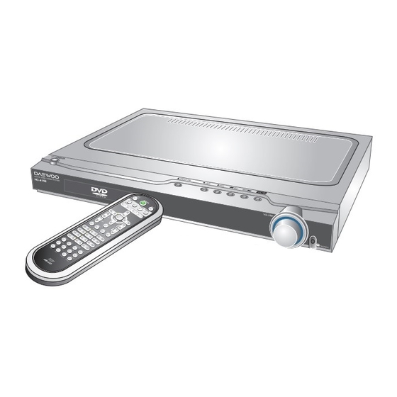
Page 6: Location Of Users Controls
3. Location of Users Controls Front Panel : HC-4130X 1. STANDBY/ON button with LED lamp 7. STOP ( ) button 2. DISC TRAY 8. PREV ( ) button 3. Remote Control Sensor 9. NEXT ( ) button 4. OPEN/CLOSE ( ) button 10. -
Page 7: Rear Panel
3. Location of Users Controls Rear Panel 11 12 1. Power cord 10. DIGITAL OUTPUT jackj 2. FM ANTENNA connector 11. VIDEO IN jacks 3. SUBWOOFER SPEAKER connectors 12. VIDEO OUT jacks 4. CENTER SPEAKER connectors 13. S VIDEO MONITOR OUT jack 5. -
Page 8: Remote Controller
3. Location of Users Controls Remote Controller 1. STANDBY/ON button 2. OPEN/CLOSE button 3. MUTE button 4. INPUT SELECTOR: DVD button/ TV SYSTEM(PAL/NTSC: DVD only) button 5. INPUT SELECTOR: VIDEO, TV/AUX button 6. INPUT SELECTOR: TUNER button 7. FAST REVERSE(FR) ( ) button 8. -
Page 9: Connecting To Equipment
4. Connecting to Equipment Connecting to TV 21-Pin SCART Cable(not included) to 21-pin SCART input terminal on TV SCART Specification : Composite and Component Video output(DVD, Video)Audio L/R Output(DVD only) for EU version: optional If the TV or monitor is equipped with an S video input, make the S video connection in addition to the normal video connection. The S video connection will provide higher quality picture playback. -
Page 10: Connecting To Speaker
4. Connecting to Equipment Connecting to Speaker Before connecting This machine is designed to reproduce optimum sound quality when speakers with the specified impedance below are connected. Please check the following information and choose speakers with appropriate impedance for the connections. Front speakers / Center speaker / Surround Speakers : 6 ohms min. -
Page 11: Firmware Upgrade
5. Firmware Upgrade Preparing the Firmware Upgrade 1. Write a disc to Update file by PC Writing Program. 2. A size of dummy folder is more than 10M bite. (ex : font_dw, attached picture) 3. Put Firmware file in a disc. •... - Page 12 5. Firmware Upgrade Read the Disc, Checksum Check and Update New Firmware. READING OK FLASH CHECKSUM OK ERASE/WRITE Caution • While updating, if the door opened or closed by touch, or power button is pressed, the Flash Memory will be damaged. Completed Update.
-
Page 13: Trouble Shooting Guide
6. Trouble Shooting Guide Audio Part 1. BASIC OPERATING START Is Standby LED Check Power Supply Circuit. Check Connection CN701. Turn Power on. Is Power on? Check DVD Processor Circuit. IC501 Block. Does Initial read work? Check DVD Mechanism. Check RF Circuit IC301. Does It Play? Check DVD Region. - Page 14 6. Trouble Shooting Guide Front Circuit 1. INITIAL OPERATING START Is Standby LED on? Is Power on? Check Connection CN701. Check Power Supply. Is Power on? Check if IC501 pin 207 is high? Replace Reset IC. IC508. Check OSC waveform of XC501.
- Page 15 6. Trouble Shooting Guide Front Circuit Check if pwr_on of IC208 is high? Check if display of Logo on TV? Check Connection between Main and Mechanism. Replace DVD Mechanism. Check I2C Line of IC504. Check Devices connected I2C Line. IC201, IC401, IC408. Check interface of VFD Driver Check VFD Data Interface.
- Page 16 6. Trouble Shooting Guide Audio Part 3. AUDIO Abnormal Audio Abnormal of DVD Function Video Input Function. Tuner Input Function. Digital Audio Input Function. Check if the I2S output of IC501 is ok? Replace IC501. Check if the I2S input of IC201 is ok? Check Schmitt Triger IC.
- Page 17 6. Trouble Shooting Guide Audio Part 3. AUDIO Abnormal Audio Abnormal of Video Input Function Check if the I2S output of IC401 is ok? Check if I2C between IC501 is ok? Check I2C Line. Check if I2S between IC406 is ok? Check I2S output of IC406.
- Page 18 6. Trouble Shooting Guide Audio Part 3. AUDIO Abnormal Audio Abnormal of Tuner Function Check if the Data Interface is ok? Check if the Tuner data is Check IC207 Data Interface Stereo, Tuned, PLL_CE. Check if the RDS data is Check IC501 Data Interface RDS_CLK, RDS_DATA Check if the I2S...
- Page 19 6. Trouble Shooting Guide Audio Part 3. AUDIO Abnormal Audio Abnormal of Digital OPTICAL INPUT & COAXIAL INPUT Audio Input Function Check if the Input Select is Check if the Data interface is ok? Check IC207 Data Interface DATA, CLK, 41 17_CS Check if the I2S output of IC407 is ok?
- Page 20 6. Trouble Shooting Guide Audio Part 4. AUDIO LINE OUTPUT Abno rmal Audio Abnormal of H/P Output Check if the output of IC501 pin121 is ok? Replace IC501. Check if the output of IC408 is ok? Check if I2S between IC501 is ok? Check I2S Line.
- Page 21 6. Trouble Shooting Guide Audio Part 4. AUDIO LINE OUTPUT Abno rmal Audio Abnormal of Rec Output Check if the output of IC501 pin121 is ok? Replace IC501. Check if the output of IC408 is ok? Check if I2S between IC501 is ok? Check I2S Line.
- Page 22 6. Trouble Shooting Guide Audio Part 4. AUDIO LINE OUTPUT Abno rmal Audio Abnormal of Subwoofer Output Check if the output of IC501 pin120 is ok? Replace IC501. Check if the output of IC408 is ok? Check if I2S between IC501 is ok? Check I2S Line.
- Page 23 6. Trouble Shooting Guide Audio Part 4. AUDIO LINE OUTPUT Abno rmal Audio Abnormal of Optical Output Check if the output of IC501 pin124 is ok? Replace IC501. Check if the output of IC404 is ok? Check if Setu p is ok? Setting for Digital Output on Check if IC303...
- Page 24 6. Trouble Shooting Guide Audio Part 5. AUDIO CONTROL Abnormal Audio Abnormal of Volume Control Check if the data of IC501 is Check Input data of volume is ok? Check Connection CN701. Check Encoder SW. VR701. Replace IC501 Check if the I2C waveform of IC201 is ok? Check between IC501 to IC201.
- Page 25 6. Trouble Shooting Guide Audio Part 5. AUDIO CONTROL Abnormal Audio Abnormal of Remote Con trol Check if the data of IC501 is Check Input data of RMC is Check Connection CN701. Check Remote Receiver, RM701. Replace IC501...
- Page 26 6. Trouble Shooting Guide Audio Part 6. VIDEO OUTPUT Abnormal VIDEO Abnormal of Component Check if the Output of IC501 is ok? Check Crystal is ok? Replace Cystal, XC501. Check Setup is Setting for RGB Mode. Replace IC501 Check the output of IC601 is ok? Check Filter Circuit.
- Page 27 6. Trouble Shooting Guide Audio Part 6. VIDEO OUTPUT Abnormal VIDEO Abnormal of S-VIDEO Check if the Output of IC501 is ok? Check Crystal is ok? Replace Crystal, XC501. Check Setup is Setting for S-VIDEO Mode. Replace IC501 Check the output of IC601 is ok? Check Filter Circuit.
- Page 28 6. Trouble Shooting Guide Audio Part 6. VIDEO OUTPUT Abnormal VIDEO Abnormal of Composite Check if the Output of IC501 is ok? Check Crystal is ok? Replace Crystal, XC501. Replace IC501 Check the output of IC602 is ok? Check the control of Select is ok? Check Power Supply Circuit.
-
Page 29: Waveforms Of Major Check Point
6. Trouble Shooting Guide Audio Part 7. MECHA CONTROL Abnormal Control Abnormal of Open/Close Check if the data input of IC501 is ok? Check VFD data is ok? Replace Front PCB Ass’y. Check Connection CN701. Check data waveforn of VFD_DATA, CLK, CS Replace IC501 Check the output of IC303... - Page 30 6. Trouble Shooting Guide Audio Part 7. MECHA CONTROL Abnormal Control Abnormal of Disc Loading Check if the data input of IC501 is ok? Check VFD data is ok? Replace Front PCB Ass’y. Check Connection CN701. Check data waveforn of VFD_DATA, CLK, CS Replace IC501 Check the...
-
Page 31: Audio Out Signal Waveform
7. Waveforms of Major Check Method Test Point : DVD Test Disc MDVD-W111 TRACK2 Color Bar Audio Out Signal Waveform DAC Output Signal Waveform Optical Output Audio Data Signal waveform PWM Output Waveform During Normal Play Serial Data Output Waveform During Normal Play... -
Page 32: Pr Output Data Waveform In Component Output
7. Waveforms of Major Check Method Test Point : DVD Test Disc MDVD-W111 TRACK2 Color Bar Pr Output Data Waveform in Component Output Pb Output Data Waveform in Component Output Y Output Data Waveform in Component Output... -
Page 33: Compositeoutput Data Waveform In Monitor Output
7. Waveforms of Major Check Method Test Point : DVD Test Disc MDVD-W111 TRACK2 Color Bar Composite Output Data Waveform in Monitor Output S-Video Output Data Waveform... -
Page 34: Internal Block Diagram Of Ics
8. Internal Block Diagram of ICs 74HC00 74HC14 74HC374 74HCU04... - Page 35 8. Internal Block Diagram of ICs AK4117 AK5365 BA7660FS BA6287F...
- Page 36 8. Internal Block Diagram of ICs CS4360 ES6629FD/ES6698FD...
- Page 37 8. Internal Block Diagram of ICs LA7952 FAN8024DB M29W800DB LD1117A...
- Page 38 8. Internal Block Diagram of ICs PT6315 STA505...
- Page 39 8. Internal Block Diagram of ICs STA308A...
-
Page 40: Block Diagram
9. Block Diagram Main Block HC-4130(... -
Page 41: Block Diagram
9. Block Diagram SMPS Block HC-4130(... -
Page 42: Wiring Diagram
10. Wiring Diagram [HC-4130(... -
Page 43: Schematic Diagram
11. Schematic Diagram DVD Processor Section HC-4150 DVD PROCESSOR SECTION [HC-4130( IC501 ES6629FD ES6698FD PICK UP : SANYO SF-HD60/62 Only... -
Page 44: Dvd Rf Section
11. Schematic Diagram DVD RF Section [HC-4130(... -
Page 45: Video & Analog Audio Section
11. Schematic Diagram Video & Analog Audio Section HC-4150 VIDEO & ANALOG AUDIO SECTION [HC-4130(... -
Page 46: Ddx Section
11. Schematic Diagram DDX Section HC-4130( HC 4130 DDX ECTION... -
Page 47: Pwm Amp. Section
11. Schematic Diagram PWM Amp. Section HC-4130( HC-4130 PWM MP SECTION... -
Page 48: Front Section
11. Schematic Diagram Front Section HC-4130(... - Page 49 11. Schematic Diagram SMPS Section [HC-4130(...
-
Page 50: Exploded View And Mechanical Parts List
12. Exploded View and Mechanical Parts List HC-4130(... -
Page 51: Exploded View And Mechanical Parts List
12. Exploded View and Mechanical Parts List HC-4130(... - Page 52 PCB MAIN ASS'y_ASA Mech [9CDC072200 : HC-4130] Loc. Part Code Part Name Description Remark B001 9CD6592700 PCB MAIN 344 X 160 1.6T FR-4 BD801 5LX100J001 COIL BEAD 3.6PI X 6MM 100 OHM,100MHz BD802 5LX100J001 COIL BEAD 3.6PI X 6MM 100 OHM,100MHz CE201 CEXF1H220V C ELECTRO...
- Page 53 Loc. Part Code Part Name Description Remark CE606 CEXF1H220V C ELECTRO 50V RSS 22MF CE607 CEXF1E470V C ELECTRO 25V RSS 47MF (5X11) TP CE608 CEXF1C102V C ELECTRO 16V RSS 1000MF (5X11) TP CE609 CEXF1C101V C ELECTRO 16V RSS 100MF (5X11) TP CE610 CEXF1C101V C ELECTRO...
- Page 54 Loc. Part Code Part Name Description Remark HC211 HCBK104KBA C CHIP CERA 50V X7R 0.1MF Z 1608 HC212 HCBK104KBA C CHIP CERA 50V X7R 0.1MF Z 1608 HC213 HCBK104KBA C CHIP CERA 50V X7R 0.1MF Z 1608 HC214 HCBK104KBA C CHIP CERA 50V X7R 0.1MF Z 1608 HC216 HCBK104KBA C CHIP CERA...
- Page 55 Loc. Part Code Part Name Description Remark HC420 HCBK104KBA C CHIP CERA 50V X7R 0.1MF Z 1608 HC421 HCBK104KBA C CHIP CERA 50V X7R 0.1MF Z 1608 HC422 HCQK220JBA C CHIP CERA 50V CH 22PF J 1608 HC423 HCBK104KBA C CHIP CERA 50V X7R 0.1MF Z 1608 HC424 HCBK104KBA C CHIP CERA...
- Page 56 Loc. Part Code Part Name Description Remark HC538 HCBK153KBA C CHIP CERA 50V X7R 0.015MF K 1608 HC540 HCBK104KBA C CHIP CERA 50V X7R 0.1MF Z 1608 HC541 HCBK104KBA C CHIP CERA 50V X7R 0.1MF Z 1608 HC542 HCBK104KBA C CHIP CERA 50V X7R 0.1MF Z 1608 HC543 HCBK104KBA C CHIP CERA...
- Page 57 Loc. Part Code Part Name Description Remark HC826 HCBK105KCA C CHIP CERA 50V X7R 1MF K 2012 HC827 HCBK105KCA C CHIP CERA 50V X7R 1MF K 2012 HC828 HCBK105KCA C CHIP CERA 50V X7R 1MF K 2012 HC829 HCBK105KCA C CHIP CERA 50V X7R 1MF K 2012 HC830 HCBK105KCA C CHIP CERA...
- Page 58 Loc. Part Code Part Name Description Remark HL502 5LX600K841 CHIP BEAD FB 60 OHM 100MHZ 2012 HL503 5LX600K841 CHIP BEAD FB 60 OHM 100MHZ 2012 HL505 5LX600K841 CHIP BEAD FB 60 OHM 100MHZ 2012 HL506 5LX600K841 CHIP BEAD FB 60 OHM 100MHZ 2012 HL507 5LX600K841 CHIP BEAD...
- Page 59 Loc. Part Code Part Name Description Remark HR310 HRFT102JBA R CHIP 1/10 1K OHM J 1608 HR311 HRFT332JBA R CHIP 1/10 3.3K OHM J 1608 HR312 HRF4109JEA R CHIP 1/4 1OHM J 3216 HR313 HRF4109JEA R CHIP 1/4 1OHM J 3216 HR314 HRF4109JEA R CHIP...
- Page 60 Loc. Part Code Part Name Description Remark HR440 HRFT104JBA R CHIP 1/10 100K OHM J 1608 HR441 HRFT750JBA R CHIP 1/10 75 OHM J 1608 HR442 HRFT101JBA R CHIP 1/10 100 OHM J 1608 HR443 HRFT104JBA R CHIP 1/10 100K OHM J 1608 HR444 HRFT103JBA R CHIP...
- Page 61 Loc. Part Code Part Name Description Remark HR525 HRFT512JBA R CHIP 1/10 5.1K OHM J 1608 HR526 HRFT103JBA R CHIP 1/10 10K OHM J 1608 HR527 HRFT122JBA R CHIP 1/10 1.2K OHM J 1608 HR529 HRFT203JBA R CHIP 1/10 20K OHM J 1608 HR530 HRFT683JBA R CHIP...
- Page 62 Loc. Part Code Part Name Description Remark HR820 HRF4220JEA R CHIP 1/4 22 OHM J 3216 HR821 HRF4220JEA R CHIP 1/4 22 OHM J 3216 HR822 HRF4399JEA R CHIP 1/4W 3.9 OHM J 3216 HR823 HRF4399JEA R CHIP 1/4W 3.9 OHM J 3216 HR824 HRF4399JEA R CHIP...
- Page 63 Loc. Part Code Part Name Description Remark J404 Without Progressive Europe/America 9736328500 JACK RCA RCA-303A-21 (RGB 3P, Shield plate) HC-4130 : 180~265V(CE) J801 9736325000 JACK SPK PA1220601P L801 5LC150K846 COIL 15UH LPF(SPK) L802 5LC150K846 COIL 15UH LPF(SPK) L803 5LC150K846 COIL 15UH LPF(SPK) L804 5LC150K846...
- Page 64 Loc. Part Code Part Name Description Remark JW709 W581GY7595 WIRE JUMPER AWG22 1/0.65 SN 7.5 AUTO JW710 W581GY1005 WIRE JUMPER AWG22 1/0.65 SN 10 AUTO JW711 W581GY7595 WIRE JUMPER AWG22 1/0.65 SN 7.5 AUTO JW712 W581GY6095 WIRE JUMPER AWG22 1/0.65 SN 6 AUTO JW713 W581GY12J5 WIRE JUMPER...
- Page 65 Loc. Part Code Part Name Description Remark HC-4130 All Model CE906 CEXF1V222C C ELECTRO 2200uF 35V RUS 105℃ HC-4130 All Model CE907 CEXF1V102V C ELECTRO 1000uF 35V CE908 CEXF1E471C C ELECTRO 470uF/25V RUS 105℃ CE909 CEXF1C471V C ELECTRO 470uF/16V RSS HC-4130 All Model CE910 CEXF1V221C...
- Page 66 Loc. Part Code Part Name Description Remark IC905 1ET1103--- IC PHOTO COUPLER ET1103 IC906 1KIA7912AP KIA7912AP (MOLD) IC907 1TL431A--- IC SHUNT REG TL431 IC908 1TL431A--- IC SHUNT REG TL431 Open 90~135V, 180~265V IC981 1STR83145- IC TRIAC STR83145 Free Volt W581GY12J5 WIRE JUMPER AWG22 1/0.65 SN 12.5 AUTO HC-4130 : 90V~135V(UL)
- Page 67 Loc. Part Code Part Name Description Remark R924 RS01Y129J- R METAL OXIDE FILM 1W 1.2 OHM J R925 RS01Y680J- R METAL OXIDE FILM 1W 68 OHM J R926 RD-AZ153J- R CARBON FILM 1/6 15K OHM J R927 RD-AZ822J- R CARBON FILM 1/6 8.2K OHM J R928 RD-AZ182J-...
Need help?
Do you have a question about the HC-4130X and is the answer not in the manual?
Questions and answers